
Abstract
Friction stir welding process is one of the solid-state welding processes, which is suitable to weld a range of similar and dissimilar material combinations by moving a shouldered, rotating tool along the joint line of weld materials. In this work, friction stir welding tools with square, circular, and triangular pin profiles are used to join the aluminum alloy AA6063-T6 flat plates. Acoustic emission technique is applied to monitor and analyze the effect of tool pin profile on tensile strength of the weld joints. A correlation study was made between the different acoustic emission signal parameters with the tensile strength of the weld joints. The proposed approach will be useful for in-process monitoring and control of the weld quality in friction stir welding process.
Introduction
Friction stir welding (FSW) is a solid-state metal-joining process invented at The Welding Institute (TWI) in 1991, in which a nonconsumable rotating shoulder pin–type tool is plunged slowly into the butting faces of the work pieces and navigated along the joint line. 1 Schematic diagram of the FSW process is shown in Figure 1. The relative motion between the tool pin and the work plate generates frictional heat that develops a plasticized region around the tool and forms a solid-phase joint. FSW demonstrates good weldments when joining aluminum alloys, steel, titanium, and dissimilar alloys. This technique has been applied for welding aluminum alloys in aerospace, automotive, and ship building industries. 2 FSW provides enhanced joint properties and performance, low distortion in the part after welding, a major reduction in production costs, and less skilled labor over conventional techniques due to automation. 3
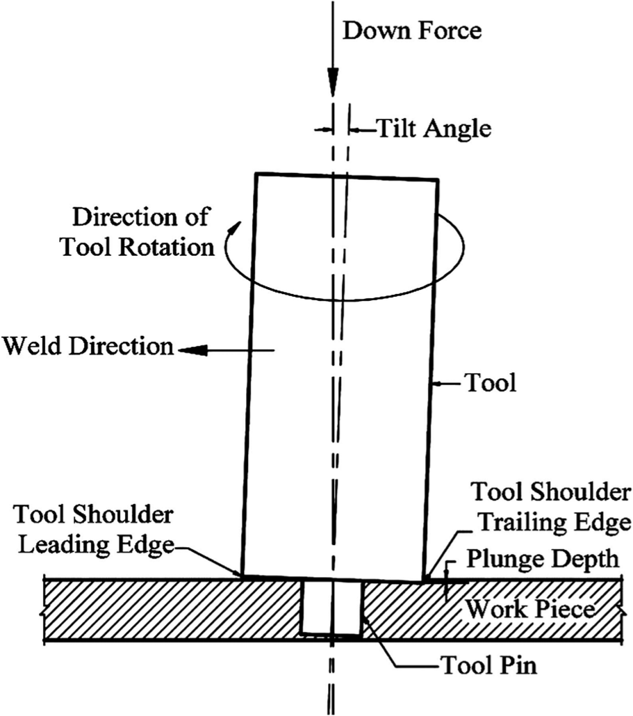
Schematic diagram of a typical FSW process and tool.
Attempts have been made to investigate the effect of tool pin profiles and welding parameters on the tensile strength of weld joints in FSW process. Influence of pin shape and the tool rotational speed has been analyzed on the friction stir processing and found that the weld parameters and tool pin shape play a major role in deciding weld quality. 4 An experimental study has been carried out to investigate the effect of tool rotational speed and pin profile on yield strength and elongation of the weld joints. 5 The effect of welding speed and tool pin profiles on tensile strength of weld joints was studied for FSW of AA6082-O aluminum alloy. 6 The influence of specific tool geometry, speed, and spindle torque on heat generation was analyzed for friction stir processing. 7 The effect of pin profiles and welding speed on tensile properties of weld joint was studied for dissimilar aluminum alloys. 8 The influence of tool design on the mechanical properties and microstructure in FSW was analyzed and found that the material flow and the quality of weld joints are primarily influenced by tool geometry and process parameters. 9 Hence, monitoring of FSW process is essential for understanding the process and tool condition.
Acoustic emission (AE) technique has been applied to analyze and monitor the varieties of machining processes. 10 AE is the phenomenon by which transient elastic waves are generated by rapid release of energy from localized sources within a deforming material. AE technique is found to be a feasible approach for detecting tool profile, material flow pattern, microstructures, and mechanical properties using AE signals in FSW process. 11 The features of typical AE signals are time of hit, rise time, amplitude, counts, duration, and frequency. These features can be analyzed to classify the source of AE signal as noise or defect related. Cumulative AE counts were quantitatively correlated with the joint strength of welds during welding process. 12 Han-Ki et al. 13 have studied the relationship between the tensile strength of weld joint and weld parameters using AE technique. Advanced signal processing techniques have been developed for monitoring the FSW process using the AE signals. 14
From the literature review, it can be observed that FSW process is widely applied for joining aluminum alloys. Many investigations have been carried out to study the effect of tool design and process parameters on the tensile strength of weld joints. However, the application of AE technique for monitoring the FSW process is found to be limited. The present work aims at developing an approach based on AE technique for in-process monitoring of tensile strength during FSW process with different pin profiles.
Experimental setup
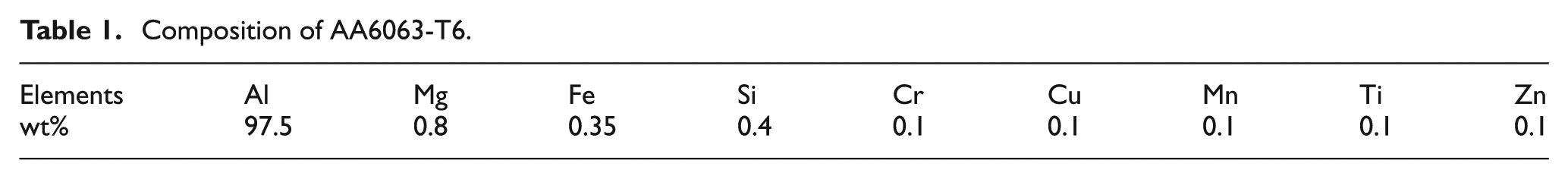
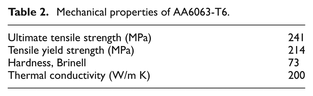
The experiments were carried out using a conventional milling machine with a vertical attachment, a rigid clamping fixture, and an automatic feed control system. The schematic arrangement of the experimental setup is depicted in Figure 2. The milling machine spindle has a speed range of 45–2000 r/min, a maximum table load of 250 kg, and a spindle motor power of 5 HP. In this investigation, AA6063-T6 aluminum alloy plates of size 100 × 50 × 6 mm were used as the work material for butt welding, which is widely used in architectural fabrication and furniture. The chemical composition and mechanical properties of AA6063-T6 are presented in Tables 1 and 2.
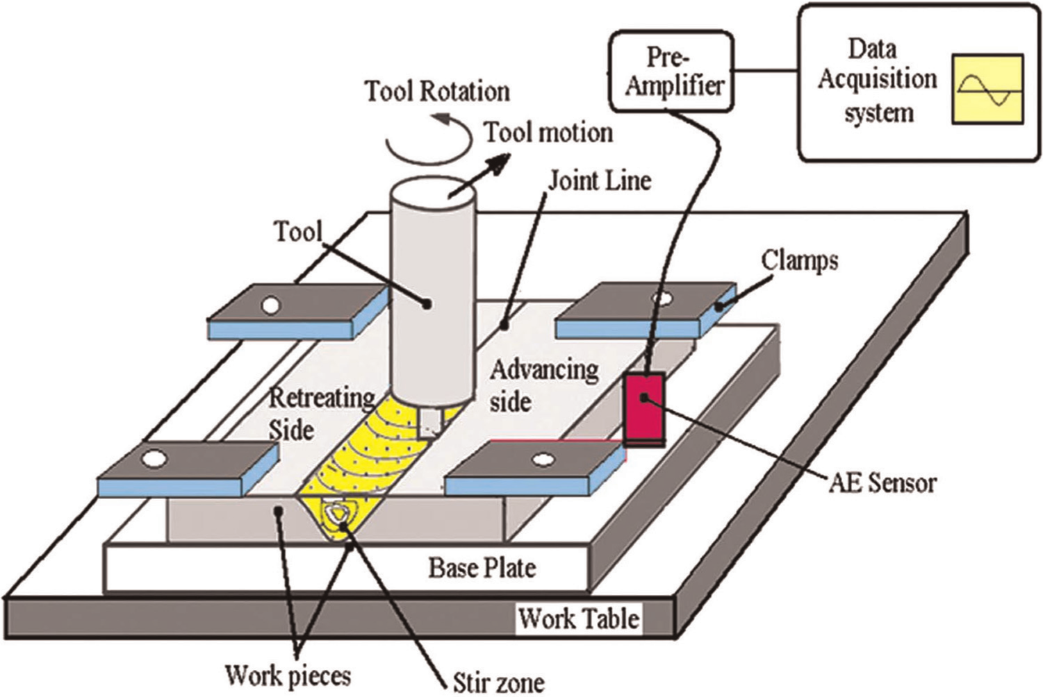
Schematic diagram of experimental setup for friction stir welding.
Composition of AA6063-T6.
Mechanical properties of AA6063-T6.
A welding speed of 40 mm/min and a spindle speed of 1000 r/min were selected during the welding process. Plunge depth was maintained at 0.3 mm. Single-pass welding procedure was used to fabricate the butt joints.
Configuration of tool geometry
The selection of tool material and size is one of the important aspects of FSW process. The FSW tool should have more strength and hardness than the work piece material. Though the tool steel is widely used as a tool material, SS316 stainless steel was considered in this experimental investigation due to higher hardness compared to aluminum and practical considerations15. The chemical composition and mechanical properties of SS316 are presented in Tables 3 and 4. The tool shoulder diameter was fixed as 18 mm, thrice of the pin diameter of 6 mm. The diameter of the tool pin was kept 6 mm, which is equal to the thickness of the work plates that are to be welded. The experiments were carried out with triangular, square, and cylindrical tool pin profiles. Schematic diagrams of the different tools and photographs are given in Figure 3(a) and (b). Each tool has a pin length of 5.5 mm. The circular pin profile tool has pin diameter equal to the thickness of the aluminum plates. For square pin, the diagonal length was equal to the thickness of the aluminum plates. Triangular tool profile is inscribed in a circle of diameter equal to aluminum plate thickness. Tool tilt angle is a parameter to improve the compaction of the material by the tool shoulder. It will also help to eliminate surface defects. For aluminum welds, a tilt angle from 0° to 2° gives a remarkable change in the microstructure development and material flow. Hence, in the present work, tilt angle was fixed as 2°.
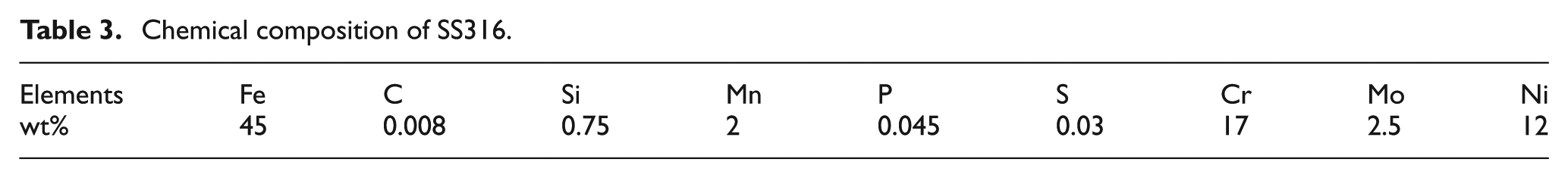
Chemical composition of SS316.
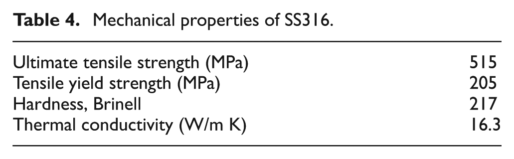
Mechanical properties of SS316.
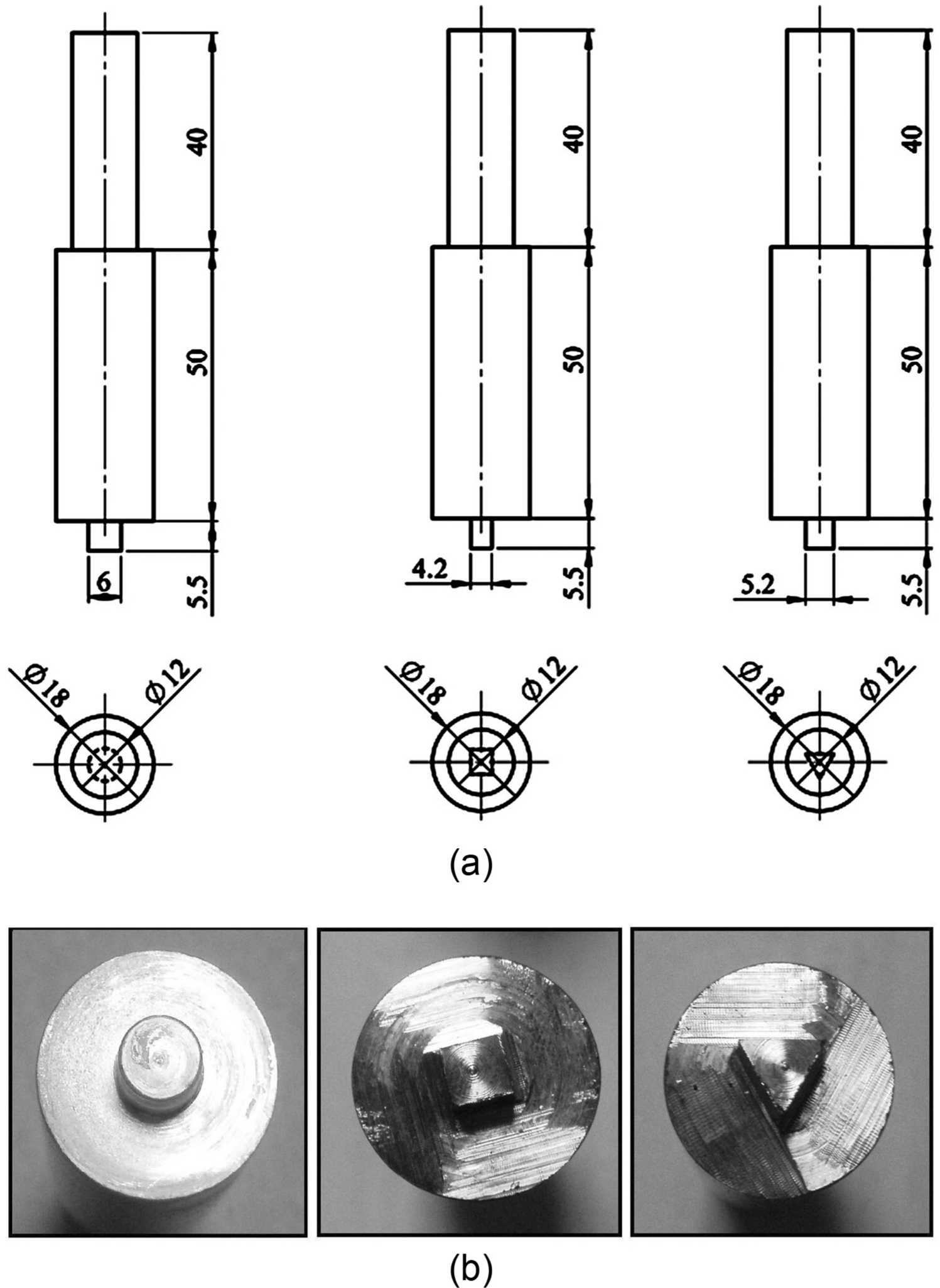
(a) Dimensions of FSW tools and (b) photographic view of FSW tool pin profiles.
AE monitoring of FSW process
In order to maintain the weld quality, it is necessary to monitor the welding process, so that the defects can be detected and avoided by regulating the process parameters. In the present work, the R80D AE sensor (Physical Acoustic Corporation) was mounted on base plate for monitoring the status of the FSW process and effective transmission of signals. A general purpose AE sensor of stainless steel case and ceramic face with an operating frequency range of 200–1000 kHz was utilized for experiments. The surface of the base plate was kept free from dirt and paint. The AE sensor was mounted closer to the weld joint line in order to avoid signal reduction. A voltage preamplifier was used for amplifying the AE signal. The AE signals were recorded with the machine in the normal running mode and found to have noises due to machine vibration at amplitudes around 30–45 dB. A threshold value was fixed to filter out the mechanical noise. The AE signal was acquired during the welding process, progressively amplified through the preamplifier with a 40-dB gain, with low-frequency noise filtering and transmitted to the signal processor. A photograph of the experimental arrangement is shown in Figure 4(a) and (b).
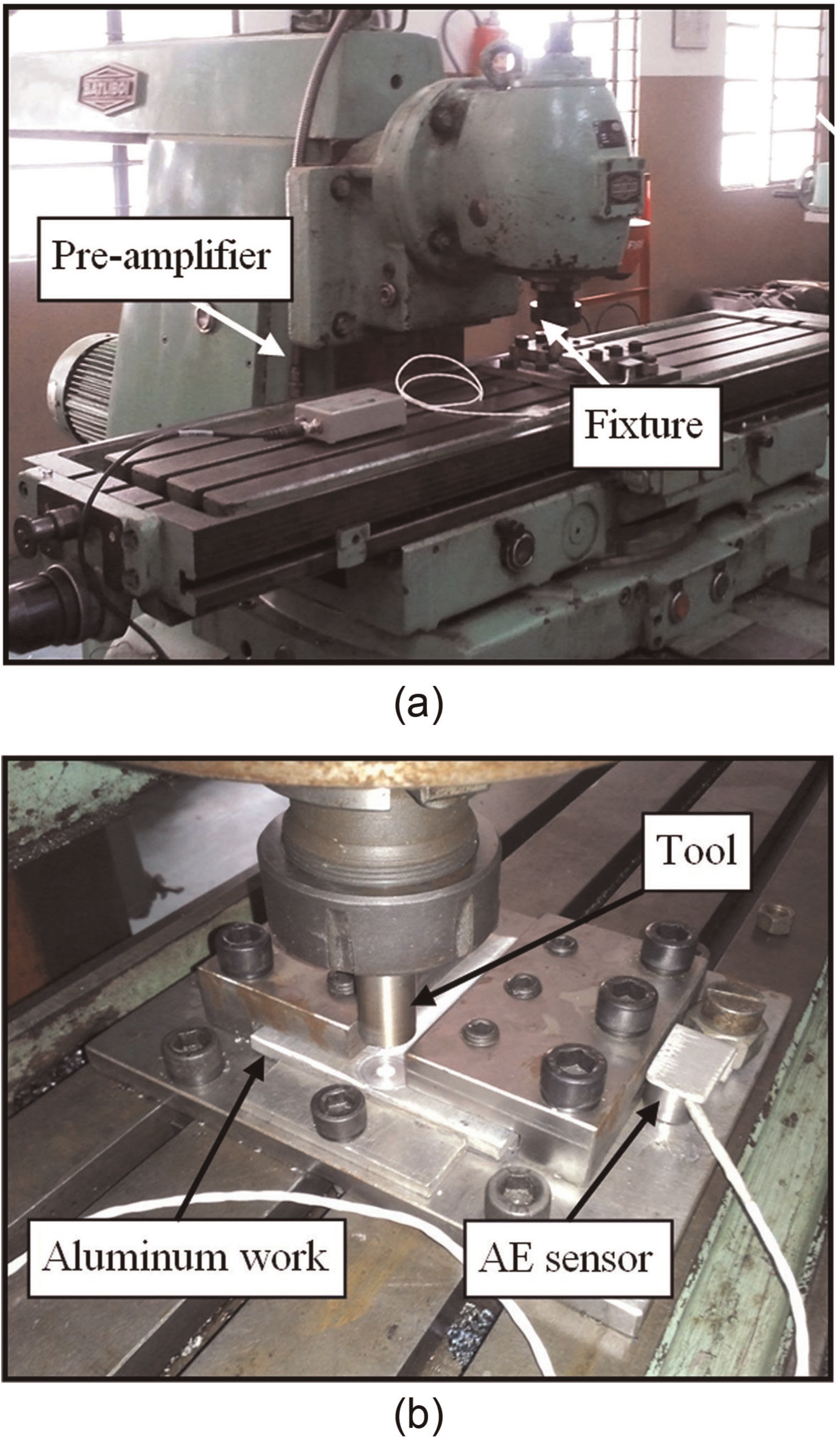
(a) Experimental setup of FSW and (b) Close up view of experimental setup.
Results and discussions
In the present investigation, AE technique was applied for analyzing the effect of circular, square, and triangular pin profiles on the tensile strength of butt-welded aluminum alloy plates. In order to verify the consistency of the measurements, three experiments were conducted using each tool and AE parameters were analyzed.
AE signals in time domain
FSW process generally produces signals that represent burst AEs, which characterize the unsteady processes. 16 Figure 5 shows the AE signal in time domain obtained during the welding process for different profiles of tool pin. The time-domain parameters such as total hits, average counts, and rise time were obtained from the AE signals for different tool profiles and are given in Table 5. From Figure 6, it was observed that total hits of the AE signal for the square pin have shown maximum value. This is due to the pulsating action of the square pin profile during the process, which has higher number of edges as compared to other profiles.
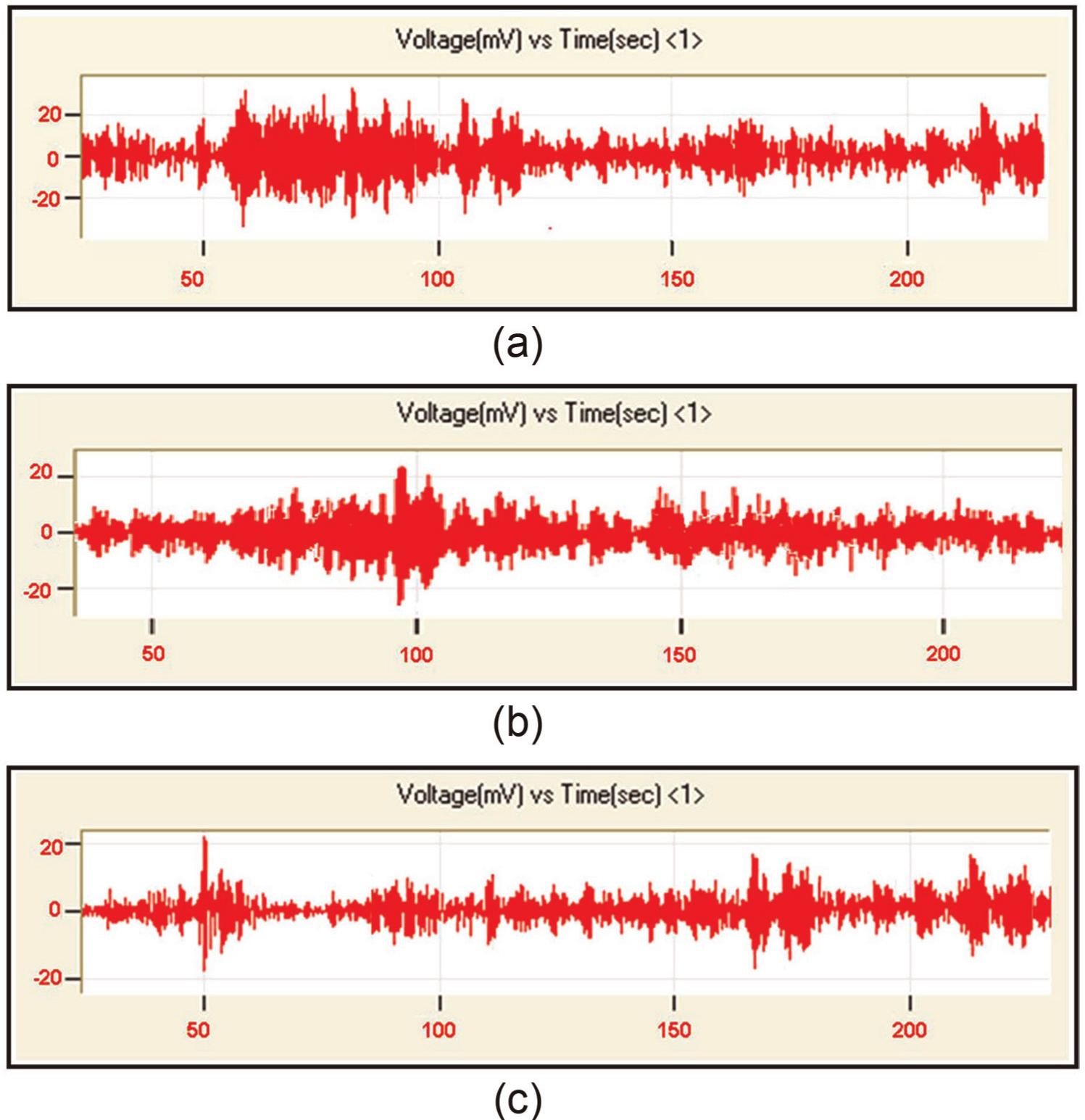
Time-domain AE signal: (a) circular pin, (b) square pin, and (c) triangular pin.
AE parameters in time domain.
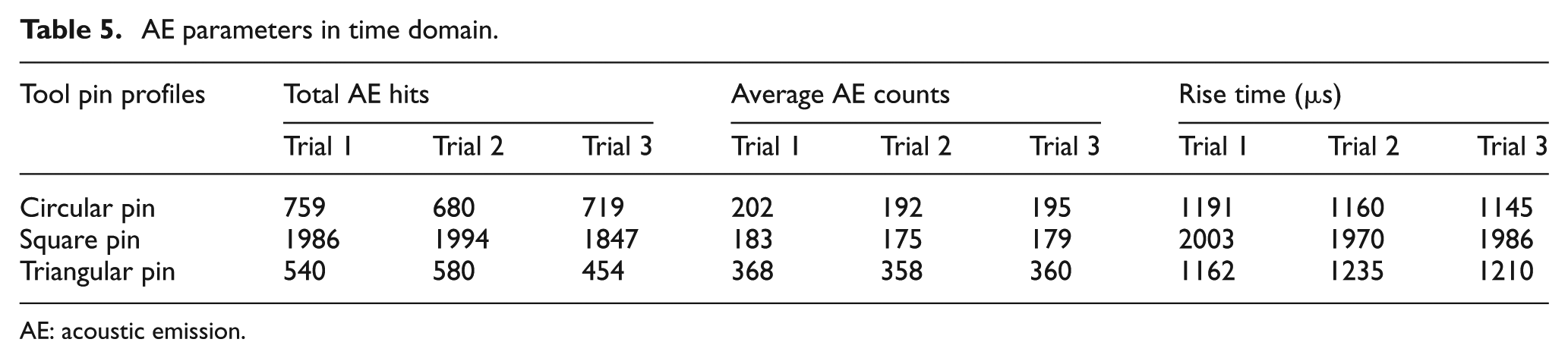
AE: acoustic emission.
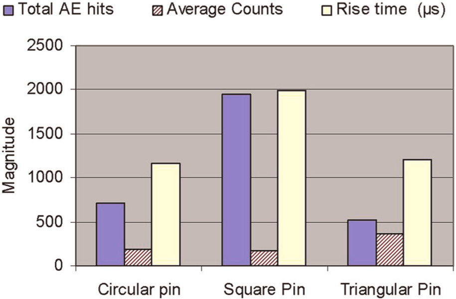
Effect of tool pin profile on total AE hits, average counts, and rise time.
AE signals in frequency domain
The Fast Fourier Transform (FFT) of the AE signals for different tool profiles are given in Figure 7. It can be observed that the frequency values of the AE signals are in the ranges of 100–180 kHz and 200–270 kHz, which are above the threshold of 45 dB. The increase in the shoulder penetration establishes a good contact between the tool shoulder surface and the surface of the material; hence, there is an increase in the power spectrum density (PSD) and the peaks are found to be in the range of frequencies 100–150 kHz. This also causes the higher frequencies in the range of 200–270 kHz. When the tool shoulder withdraws contact from work surface, the magnitude of higher frequencies also reduces. The parameters such as energy, amplitude, and average frequency were obtained from the frequency-domain data of AE signals and listed in Table 6.
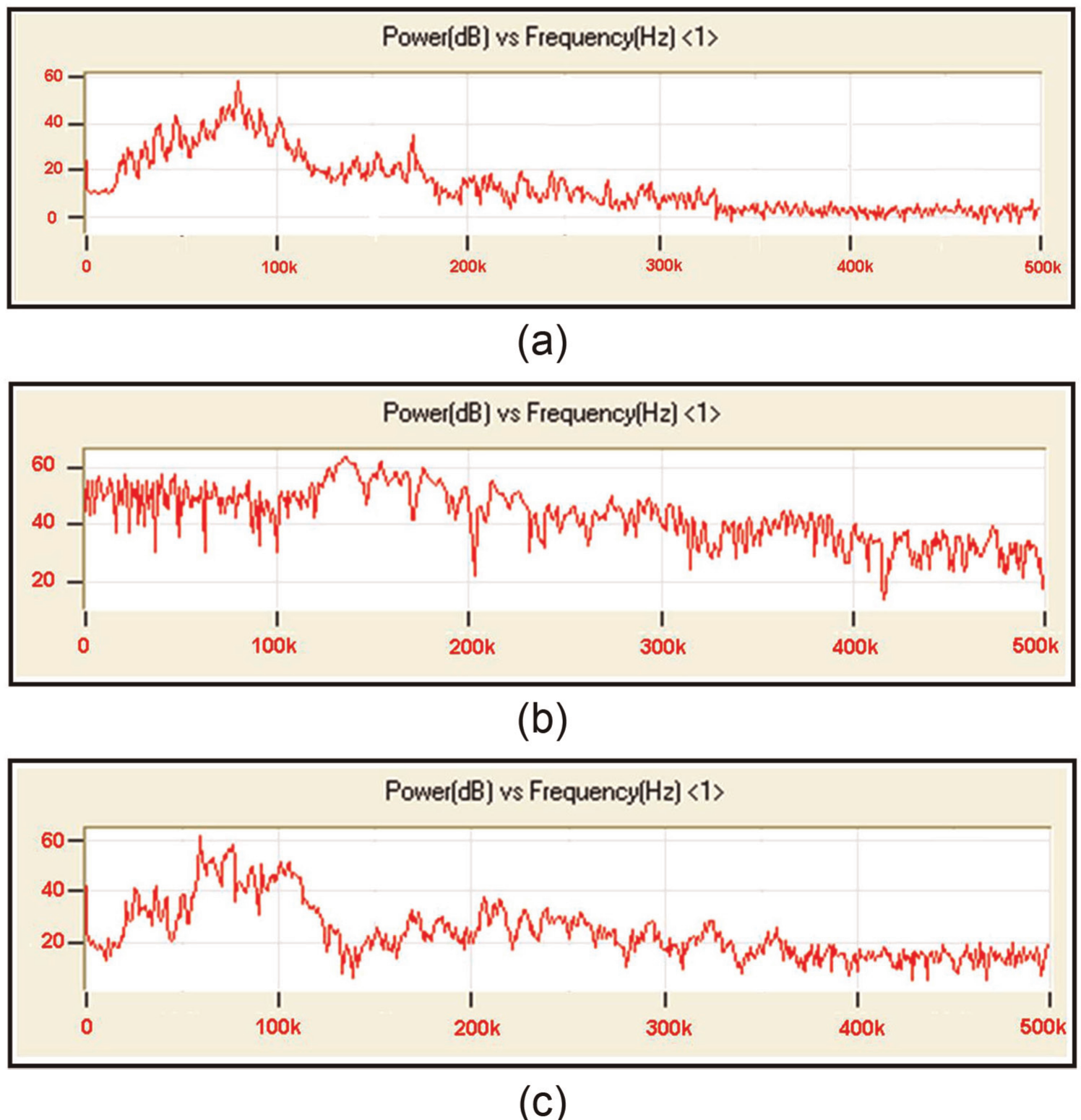
FFT plots of AE signal: (a) circular pin, (b) square pin, and (c) triangular pin.
AE parameters in frequency time domain.
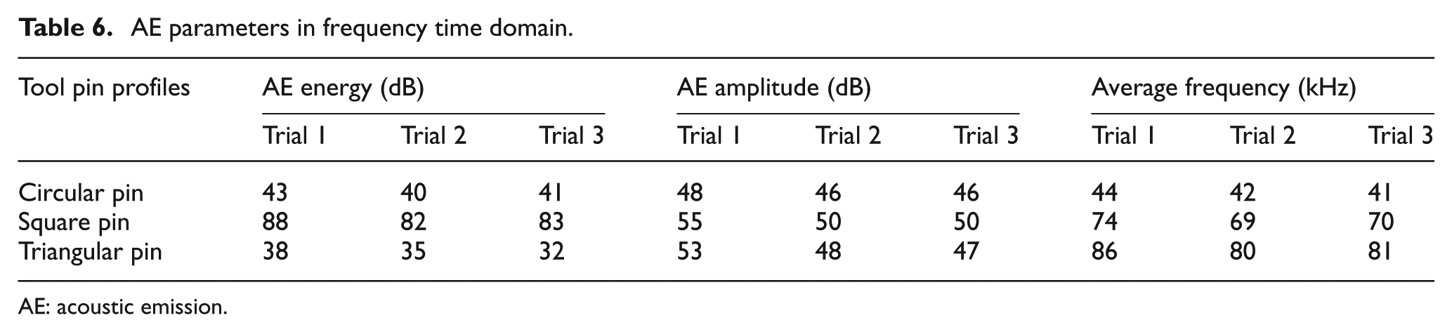
AE: acoustic emission.
The energy of the AE refers to the area of the envelope of the waveform. It can be observed that the average energy level for the square pin profile is significantly higher than the other pins from Figure 8. AE amplitude of the signal is the greatest measured voltage in a waveform and is measured in decibels. This parameter determines the detectability of the signal. It is observed that the amplitude and energy level of the AE signal are high for the square pin profile; this is due to the pulsating action of the square pin profile during the process, which has higher number of edges as compared to other profiles.
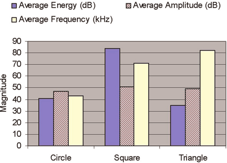
Effect of tool pin profile on AE average energy, average amplitude amplitude, and average frequency.
Weld strength analysis using tensile testing
The welded joints are machined to the required dimensions using wire-cut electrical discharge machining (EDM) to prepare tensile specimens. A sample of a friction stir welded plate is shown in Figure 9. The tensile test specimens were prepared as shown in Figure 10(a) and (b), according to the American Society for Testing and Materials (ASTM) standard, and the transverse tensile properties of the friction stir welded joints were evaluated using a computerized electronic tensometer. Stress–strain curves for the specimens obtained from different tools are given in Figure 11. The joints were visually inspected for exterior weld defects, and they were found to be free from any external defects.
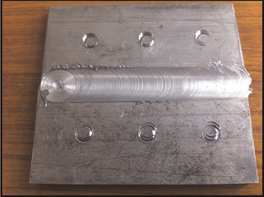
FSW specimen produced by square pin tool at 1000 r/min.
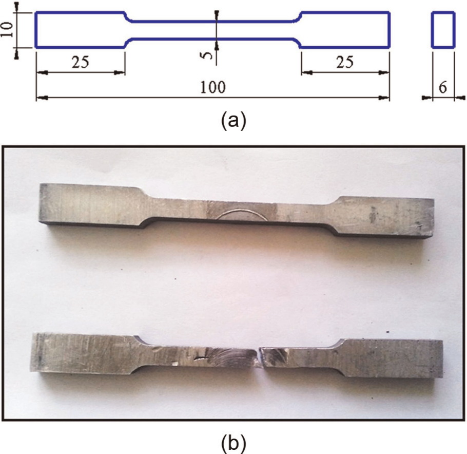
(a) Dimensions of tensile test specimen and (b) photographic view of tensile test specimen.
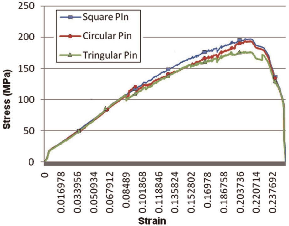
Stress–strain curve for tensile test of FSW specimens produced by different tool pin profiles.
It is observed that the specimen obtained using the square pin profile tool has an ultimate tensile strength of 196 MPa as shown in Table 7. From the results obtained on tensile testing, it is found that the tool pin shape has the significant effect on the tensile strength of the specimen. The square pin profile has four flat vertical faces, which enable higher pulsating flow of material as compared to triangular pin profile. When the tool rotates at 1000 r/min, square pin produces 66 pulses/s as compared to 50 pulses/s by the triangular profile. This improves the flow of material, thereby improving the tensile strength of the specimen.
Analysis on weld strength.
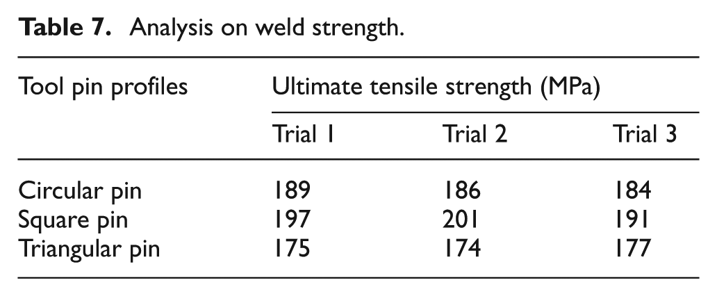
The square pin profile tool has produced FSW specimens with higher tensile strength due to more number of edges. Even though circular pin profile does not have edges, it has a higher contact surface area than other tool pin profiles. This increase in contact surface area improves the tensile strength of weld joint. The square pin profile has the advantage of more number of edges and considerable contact surface area. Triangular pin tool produces weld joints with lesser strength due to lesser contact surface area as compared to square and circular pin profiles.
Effect of tool pin profiles on tensile strength and AE parameters
The variations in the tool profile leads to changes in the contact area between tool and work material during welding, which influences tensile strength of the specimen and AE signal parameters such as total hits, average counts, rise time, and energy. In order to observe the trend of the tensile strength of the weld specimens with AE parameters for different pin profiles, a straight line is fitted between the tensile data and the AE parameters using least squares method. Figure 12 shows the estimated trend lines and correlation coefficients for the tensile strength of specimen and AE parameters for different tool pin profiles.
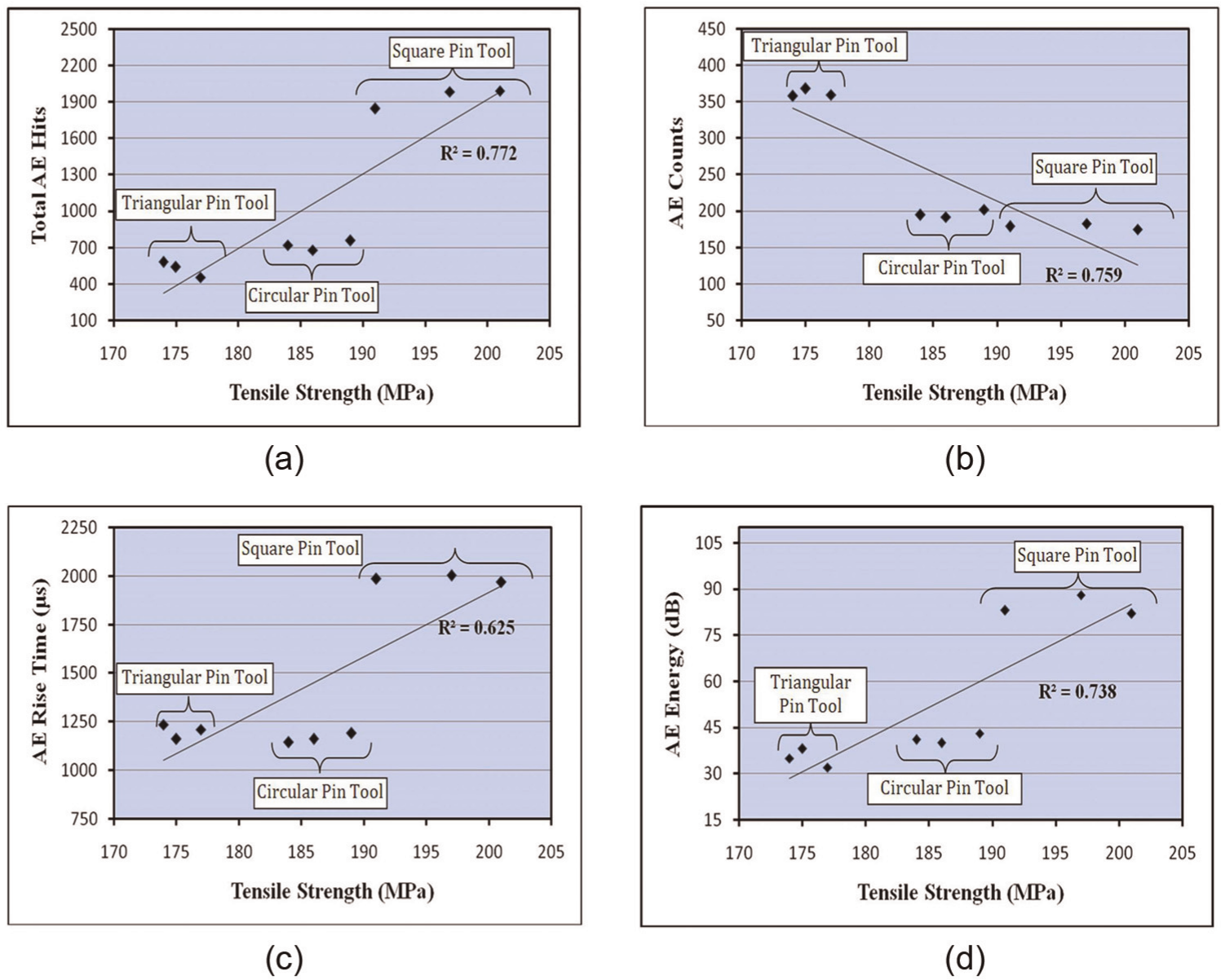
Relationship between AE parameters with tensile strength of FSW specimens produced by different tool pin profiles: (a) AE hits versus tensile strength, (b) AE average counts versus tensile strength, (c) AE rise time versus tensile strength, and (d) AE energy versus tensile strength.
AE parameters such as total hits, rise time, and energy of the AE signal are found to provide an increasing trend with respect to tensile strength of the specimen, as shown in Figure 12(a), (c), and (d), respectively. The square pin tool produces AE signal with higher amplitude and longer duration due to more number of edges in the tool pin as compared to other tools. This process leads to several threshold crossings in the AE signal and increase in the total AE hits, AE rise time, and AE energy. The surface area of circular pin profile is more than that of square and triangular pin profiles. However, the weld strength of the specimen is found to be lesser due to ineffective stirring action, which is reflected by the magnitude of AE parameters.
A decreasing trend is observed between AE average counts and tensile strength of the specimens as shown in Figure 12(b), which may be due to short-duration pulses produced by the square pin tool as compared to long-duration pulses produced by triangular pin. In addition, the contact area of the triangular pin profile is less than the circular and square pin profiles, which leads to reduction in tensile strength of the weld specimen. However, other parameters such as AE amplitude and average frequency do not show significant correlation due to scattering of data.
From the experimental results as shown in Figure 12(a)–(d), the correlation coefficients in the range of 0.62–0.77 are observed with respect to the tensile strength of the specimens in the range between 175 and 200 MPa. As the correlation coefficients provide a measure of strength of linear association between tensile strength of the weld specimens and AE parameters, a specified range for the typical AE parameters can be fixed for monitoring the tensile strength of the FSW specimen.
Conclusion
In the present work, an experimental investigation was carried out to study the application of AE approach for monitoring the tensile strength of the weld joints in FSW of AA6063-T6 alloys, under various tool pin profiles. In this study, square, circular, and triangular pin profiles are considered for the FSW process. Time-domain and frequency-domain AE parameters were calculated for the AE signals obtained to monitor the welding process and correlated with the tensile strength of the specimens. The following conclusions were drawn from this experimental investigation:
The tool pin profile affects the tensile strength of the weld joints, due to the variations in the contact area and stirring action of the tool pin, which reflects in the weld strength of the specimen and AE parameters.
Square pin profile FSW tool provides higher strength weld as compared to circular and triangular pin profiles due to faster pulsating action during welding.
Among the various AE parameters, total hits, average counts, rise time, and energy are found to be consistent with the repeated measurements.
Total AE hits are found to provide a higher correlation of 0.772 with the tensile strength of the weld joints in range of 175–200 MPa, as compared to AE rise time, AE energy, and average AE counts.
Future scope
Proposed approach can be extended for online monitoring and control of weld quality in FSW process with suitable instrumentations and control algorithms.
Footnotes
Funding
This research received no specific grant from any funding agency in the public, commercial, or not-for-profit sectors.