
Abstract
In this article, friction stir welding experiments were performed on AA 5083-H111 aluminum alloy using a tool with a triangular pin to study the effect of tool rotational speed and welding speed on the ultimate tensile strength, percentage of elongation (ε), hardness and microstructure. The investigations were done with the optical microscopy, stereomicroscopy, scanning electron microscope and energy dispersive spectroscopy. In the visual inspection, it was observed that some of nugget zones have an onion ring like features and a basin-shaped profile. The ultimate tensile strength and percentage of elongation (ε) of the welds decrease with decreasing the welding speed for the 800 r/min. On the other hand, as the welding speed increases, the UTS and ε decrease for the 1250 rpm/min, the ultimate tensile strength and percentage of elongation (ε) decrease. The main factor, which affects the reduction in both ultimate tensile strength and percentage of elongation (ε), is defects in the welds. A comparison of ultimate tensile strength and percentage of elongation (ε) as a function of tool rotational speed for the 100 mm/min showed that both ultimate tensile strength and percentage of elongation (ε) decrease with the increase in the tool rotational speed. The weld efficiency varied between 88.3% and 92% in the defect-free welds. The hardness distribution of the zones on the welds revealed that no remarkable differences exist between them. Hence, the variance on the grain sizes of zones is small.
Introduction
The nonferrous metals such as aluminum alloys are used in the automotive, shipbuilding, aircraft and railways industries due to their inherent properties such as a lightweight, low density, good machining properties, high corrosion resistance, relatively high strength and ductility, and high thermal and electrical conductivity. Despite the excellent properties of aluminum alloys, it is difficult to weld them by fusion welding or conventional welding techniques. It is well known that fusion welding or conventional welding techniques occur at the melting point of the related material and use a filler metal or shielding gas. 1 Melting and resolidification at the weld region lead to the formation of many defects such as voids, distortion, hot cracking, 2 filler metal mismatch with the base metal and the compatibility of metals in dissimilar welding. 3 Because of these defects, a reduction in the tensile properties of the weld occurs. 4 However, welding of aluminum alloys using friction stir welding (FSW) offers many advantages. FSW is a solid-state welding process invented by The Welding Institute (TWI) in 1991.2,4,5 The well-known feature of this process which defines the solid-state welding techniques is that the parts are joined below the melting temperature, and therefore, the fusion zone, melting and recast of the metal 6 do not occur at the interface of the metals. In the FSW technique, the welding is provided by a special, cylindrical tool consisting of two components: the shoulder and a profiled pin. These two parts have major functions because the amount of heat required for welding is adjusted through the tool parts. The rotating pin is positioned on butted plates and then plunged with downward force to provide pressure and friction heat (see Figure 1). At the same time, friction begins between the pin and the surface of plates, and thus, heat generation begins. With the help of the friction between the shoulder and the surface of plates, the generated heat reaches the plasticized temperature. In this stage, the pin performs two functions; one function is to mix the materials to each other and the other is to transfer the mixed material toward the weld direction. The major effective advantage of FSW is that defects that can occur due to high heat input are eliminated. This also leads to a high-strength weld when compared with conventional techniques.
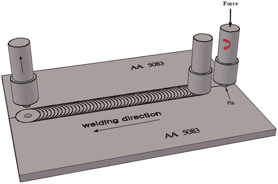
The process principles of the friction stir welding.
AA 5083 is one of the strain hardened (Al-Mg-Mn) aluminum alloys, and it is also an Mg-Mn solid solution hardened alloy. 7 Due to its high resistance to corrosion, it is used in the shipbuilding industry and for storage vessels. 8 As with other aluminum alloys, AA 5083 can be welded using conventional welding techniques. However, the use of shielding gases and filler metals in these methods may cause some defects such as voids or porosity, which greatly decreases the strength of the weld. According to Kumar et al., 9 the welds produced by conventional welding techniques have some defects due to a softening of the heat-affected zone (HAZ) in strain hardened temper.
Many researchers have studied FSW in order to determine the effects of process parameters and tool configurations on the mechanical properties and the microstructure of welds. In the study by Kumar et al., 9 an empirical model to control for process parameters has been proposed. Tool which has a flat shoulder with cylindrical pin having half of depth machined as an equilateral triangle was used in experiments. They found that all the parameters, namely, tool rotational speed (TRS), welding speed (WS), tool shoulder diameter and probe diameter, are critical process parameters affecting FSW process forces and heat input. Behnagh et al. 10 performed a series of FSW experiments to investigate the effect of parameters on hardness, corrosion resistance and wear resistance of Al5083 alloy. In the study, cylindrical pin was used. They found that the loss of mass in the parent material sample is higher than that in the FSW processed sample. The grain size is smaller in nugget zone (NZ), and the precipitates are disseminated when compared with thermomechanically affected zone (TMAZ) and HAZ. Peel et al. 11 used M5 threaded pin to perform FSW experiments to investigate the effect of tool traverse speed and tool on the weld properties. It is found that increasing the traverse speed (and hence reducing the heat input) narrows the weld zone. Sakthivel et al. 12 performed FSW experiments on AA 5215 using a threaded cylindrical pin with size of standard metric M6 to investigate the mechanical properties and microstructural aspects with various WSs. It is observed that the ultimate tensile strength (UTS) increases when decreasing the traverse speed, and good correlation exists between the mechanical properties and WSs. Attallah et al. 13 used a standard tool with a threaded cylindrical pin to investigate the effect of welding conditions on the intermetallic particle distributions, the formation of the “onion ring” structure and the banded grain structure. They found that the intermetallic particle distribution had a greater effect on the “onion ring” formation than variations in the processing parameters.
Studies in the related literature concentrate on the effect of the cylindrical threaded pin and different shoulder diameters on the hardness profiles, tensile strength and microstructure of welded zones. However, in this study, a shouldered tool with triangular profiled pin was used with the aim of providing a better mixture in the NZ. Furthermore, the literature review showed that the triangular profiled pin had not been used for AA 5083-H111, the non-heat-treatable and strain hardened Al-Mg alloy. Therefore, this study concentrates on the effect of a triangular pin coupled with welding parameters on the mechanical properties and microstructure of welds. In this way, this study contributes to the related literature based on results taken from experimental studies.
Theoretical aspects
As mentioned in section “Introduction,” FSW is performed at solid phase of material. The necessary heat for welding is generated with the friction between tool and materials, and this heat leads to softening of the material around the pin and beneath the shoulder. For the generation of heat, some mathematical approximations are used and are provided as follows14–18
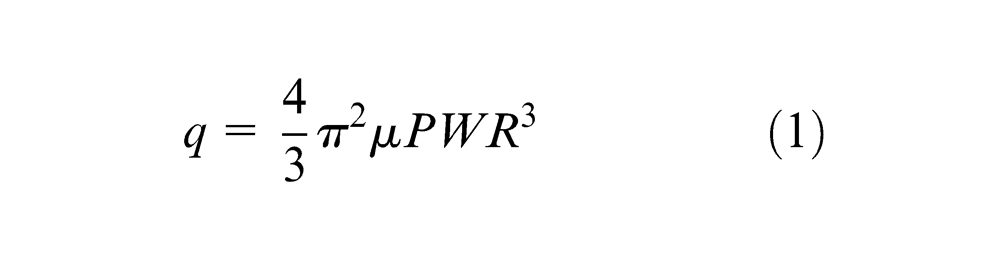
where q is the heat input, µ is the friction coefficient, P is the pressure, W is the TRS and R is the shoulder radius. The heat input per unit length is also described as a function of the WS. Accordingly, if equation (1) is associated with the WS, equation (2) is obtained as follows14–18
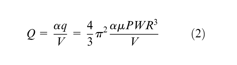
where Q is the heat input per unit length, α is the heat input efficiency and V is the WS. For a welding condition, α, µ, P and R are the constant values. In this case, Q is derived as in equation (3)14,16

where Q is the heat input per unit length, V is the WS and W is the TRS. For a welding condition, β is the constant value.
It is clear that the friction coefficient and tool properties are constant for a welding process, and the TRS and WS are the main variables of heat input per unit. This means that the welding efficiency (strength of weld) is affected by variation in the TRS and WS. The TRS is responsible for the production of heat input. However, the WS is responsible for the heat input per unit area while tool is moving along the weld zone.
Material and experimental studies
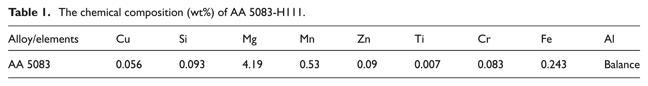
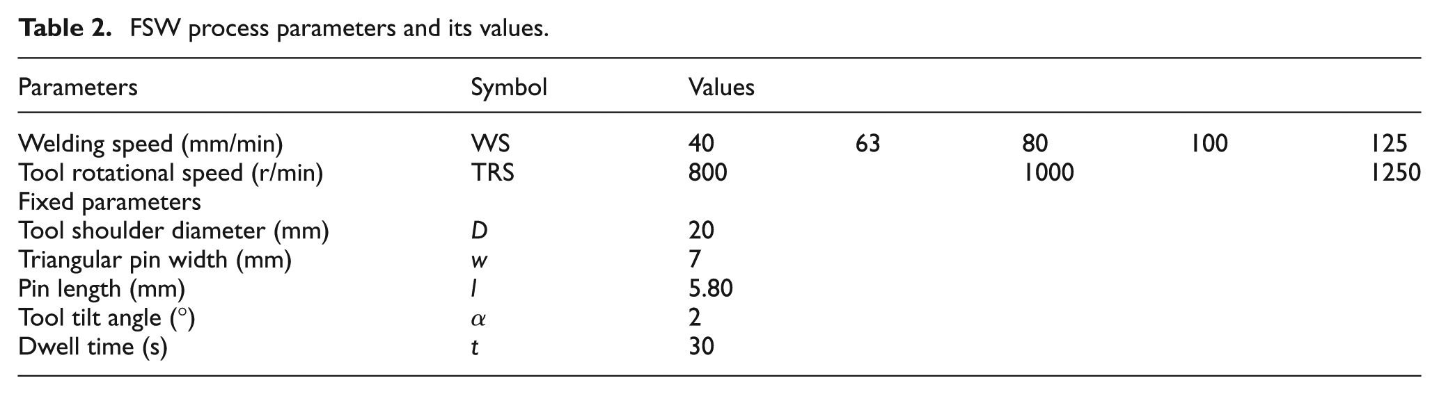
The non-heat-treatable and strain hardened Al-Mg alloy, AA 5083-H111, was selected as the base metal in the experiments. The chemical composition is given in Table 1. The friction stir butt welding experiments were performed with a universal milling machine. The experimental plate samples were prepared to a size of 200 mm × 100 mm × 6 mm. Welds were performed with nonconsumable shouldered tools with a triangular pin, as shown in Figure 2. The tool had a 20 mm shoulder diameter and a triangular pin having width of 7 mm. The tool configuration and welding parameters are presented in Table 2. During each welding, the tool was tilted by 2° to the normal direction of the tool movement and rotated clockwise. The plates to be joined were fixed on to the backing plate with studs as shown in Figure 3. A backing plate is a metal plate that is used to ensure parallelism between abutted surfaces and to prevent the movement of the plates with the effect of the force coming from the tool.
The chemical composition (wt%) of AA 5083-H111.

Tool and pin profile used in this study.
FSW process parameters and its values.
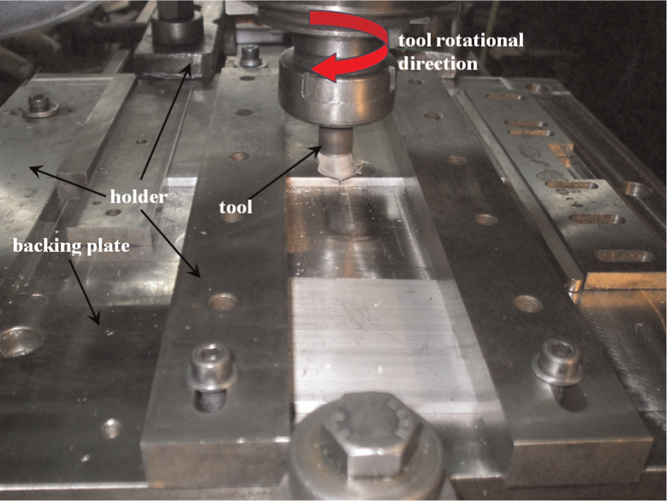
The FSW components and their placement.
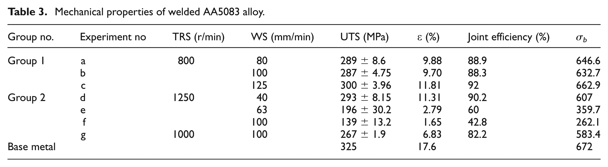
The TRS and WS were selected as process parameters, and as a result of the combination of these parameters at different values, the welding performance and weld microstructure were analyzed. The experiments were carried out according to an experimental plan given in Table 3. The mechanical properties (UTS and percentage of elongation (ε)) of the welds were considered as the weld performance.
Mechanical properties of welded AA5083 alloy.
Following welding operations, each welded sample was cross-sectioned to the tool transverse line comprising the NZ, the TMAZ and the HAZ. Both the base material (BM) and the welded samples were subject to the standard polishing processes. For the optical microscopic and macroscopic investigations, the samples were etched with 0.5% hydrofluoric acid (HF) solution. Scanning electron microscopy (SEM) was used to analyze the fracture surface and weld structure. In addition, energy dispersive spectroscopy (EDS) was used to analyze and characterize the intermetallic particles in the dimples.
The transverse tensile test samples were prepared in accordance with the ASTM E8M specification. Each test was carried out with a cross speed of 2 mm/min, using a universal tensile testing machine of 100 kN. Three tensile samples were tested, and the average of those was used to decide UTS and percentage of elongation. In order to determine the bending strength, a bending test was performed for each welding case. Rectangular specimens with dimensions of 150 mm × 20 mm × 6 mm were used for the three-point face bend testing.
Vickers microhardness test was employed to determine the hardness distribution on the cross section of the weld line. The measurements were started at the centerline of the weld, continued throughout the BMs to each side with a spacing of 1 mm and applied with a load of 100 g for 10 s. In total, 15 measurements were performed on each side of the weld.
Results and discussion
Analysis of macrostructure
Examination of the macrostructure and microstructure of each weld was performed at the transverse cross section after the etching process. The macrostructure of the welds for existing experimental conditions are shown in Figure 4(a)–(g). It is obvious that apart from Figure 4(e)–(g), the other welds produced are defect free, suggesting that each weld case can be used as an optimal condition. Visual inspection of the NZ showed that it is formed into circular or elliptical shape consisting of onion rings. In the study by Attallah et al., 13 the onion rings have been explained as fine and coarse grain bands and it is shown as a result of etching response in the NZ. In this study, except in Figure 4(f) and (g), the onion rings in the NZ are clearly detected and visible. As can be seen from the welds made at 800 r/min, the rings in the NZ are increasingly disappearing as the WS increases. However, the ring structures in the welds produced at 1250 r/min are almost the same and it is hard to visible. It is well known that higher TRS and lower WS produce higher heat. While the onion ring can be clearly detected in Figure 4(a)–(c), it is hard to see the onion rings in Figure 4(d)–(g). Therefore, it is thought that the visibility of onion ring is remarkable in lower TRS and higher WS. According to some researchers,13,19–23 the visibility of onion rings in the NZ depends on grain size and frictional heat, and also, the onion ring formation tendency 21 is decreased with increase in temperature (higher TRS and lower WS).
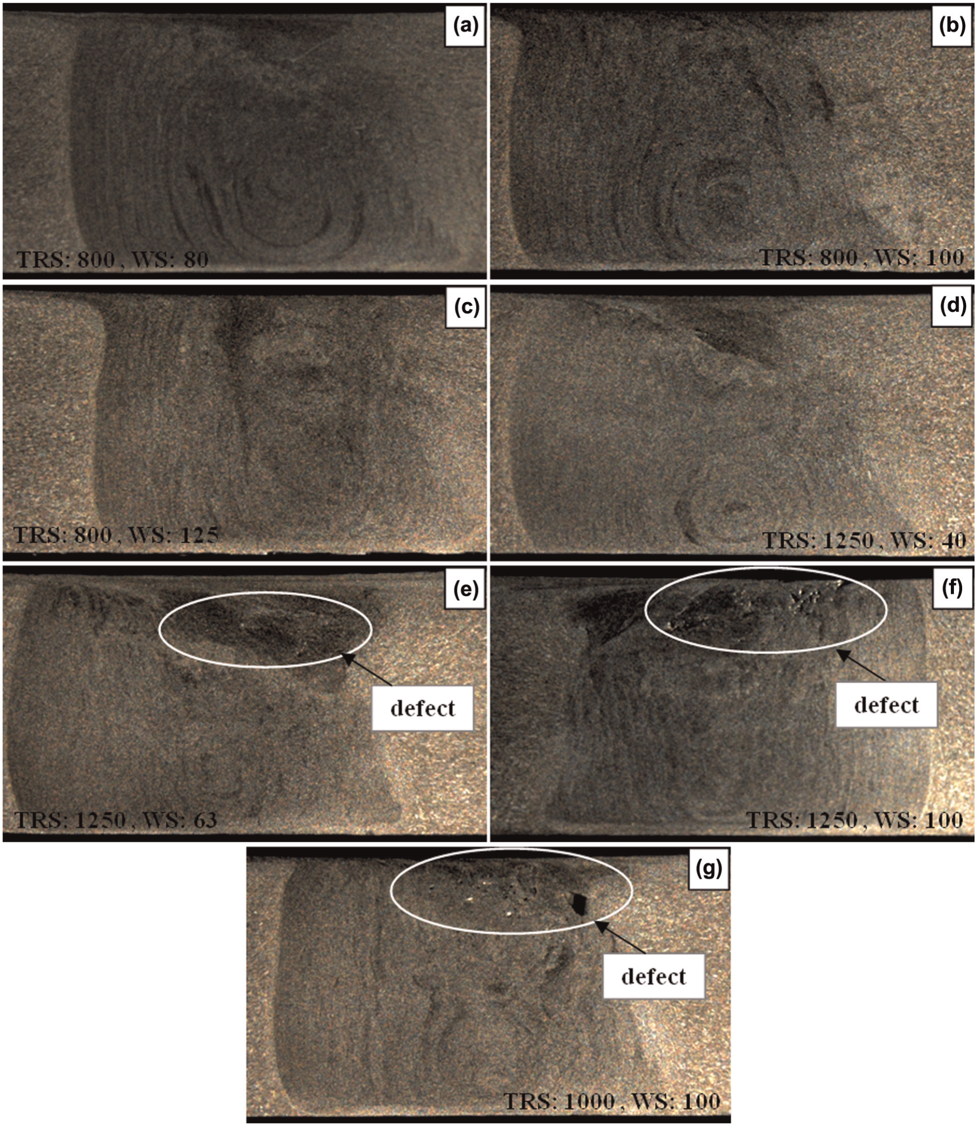
The macrostructure of weld zones.
During the FSW, typical zones such as NZ, TMAZ and a part of HAZ occurred, and for this study, these can clearly be detected in Figure 5 as in the other welded welds. The weld shown in Figure 5 was made at 800 r/min and 80 mm/min. From Figure 5, one can see that the TMAZ consists of plastically deformed and elongated grains through to the pin rotation direction. TMAZ occurs under both the thermal and mechanical effects of the shoulder and pin, which produce a transformation with the effect of maximum shear stress. However, the NZ has fine and equiaxed grains due to the effect of intense plastic deformation and frictional heat. This is consistent with the general trend in the FSW application. The study by Biswas et al. 24 emphasized that the higher mechanical deformations caused by the shearing action produce a finer grain structure in the NZ. Moreover, some of the studies in the literature15,24,25 indicate that a higher strain rate or severe plastic deformation leads to an increase in the recrystallization rate. A remarkable result in this study was observed after investigation of the HAZ region, in which the grain sizes of BM and HAZ are almost the same. The trend in the hardness distribution also confirms this result. While the hardness is 76 ± 1 HV at the BM, the hardness at the HAZ is 72 ± 2 HV. This means that the variation in grain size is not large enough to produce a change in hardness. According to Threadgill et al., 26 the welded 5XXX alloys at soft tempered condition do not exhibit a HAZ.
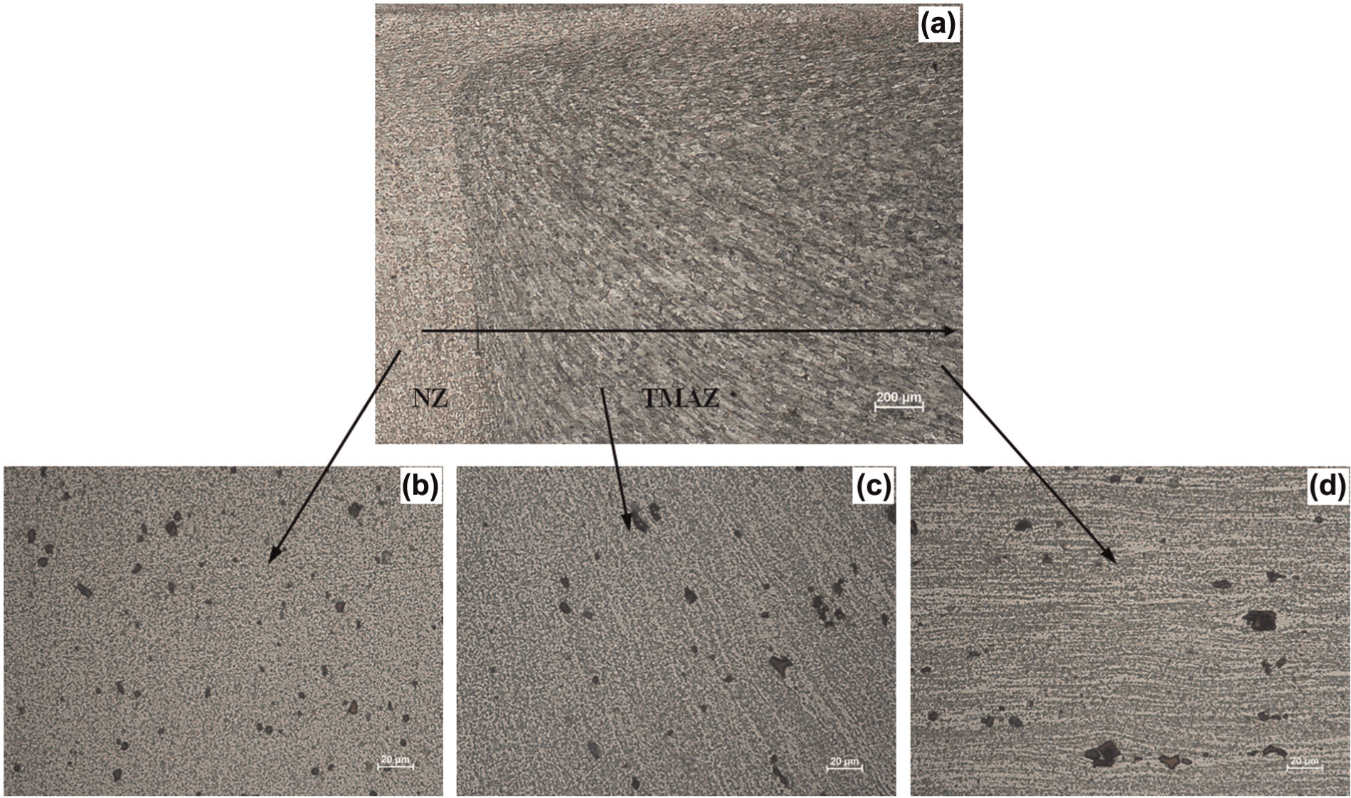
(a) Transverse section of the AA 5083-H111 plates welded with triangular pin at a tool rotational speed of 800 r/min and welding speed of 80 mm/min; optical micrographs of (b) the NZ, (c) the TMAZ and (d) the HAZ.
It is well known that the transferred heat per unit area is determined by the WS. A lower WS produces higher heat due to the higher friction time between the material and the tool. As a result of the higher heat, the heat transfer along the width increases. According to Lorrain et al., 27 frictional heat is mainly responsible for the width of the zones. According to Peel et al., 11 higher heat input results in lower WS and causes the NZ to become wider, flatter and more homogeneous. It is also emphasized that the recrystallized zone narrows with lower heat input resulting in increasing WS. The relation between the heat input and WS is reported in the literature as in equation (3). According to this relation, a higher TRS or lower WS generates higher heat. In this study, the NZ shapes in Figure 4 emphasize that the higher WS causes narrowing of the NZ. A similar result was also obtained from the increase in TRS.
The shape of the NZ for all welds was also analyzed. Depending on the TRS and WS, near similar shapes were observed in the NZ. The shape of the welds obtained is shown in Figure 4. In the visual inspection, it was observed that some of the NZs have basin-shaped profile. Also, the welds have an onion ring like structure, and the center of the onion rings has shifted from the middle of the NZ to the bottom of the weld.
The defects in the welds can easily be observed in Figure 4. A defective weld is presented in Figure 6. It is clear that there are many voids beneath the shoulder. It is believed that since the selected TRS is higher, this causes higher heat generation at the NZ. According to Liu et al., 28 the higher heat input increases the fluidity of the material and thus makes turbulence flow in the NZ. The material at the turbulence made by the triangular pin moves toward the upper surface and, depending on the WS, it produces microvoids. The other observation obtained from Figure 4 is that the defects have shifted to the retracting side, and the size of the defects increases with the increase in WS.
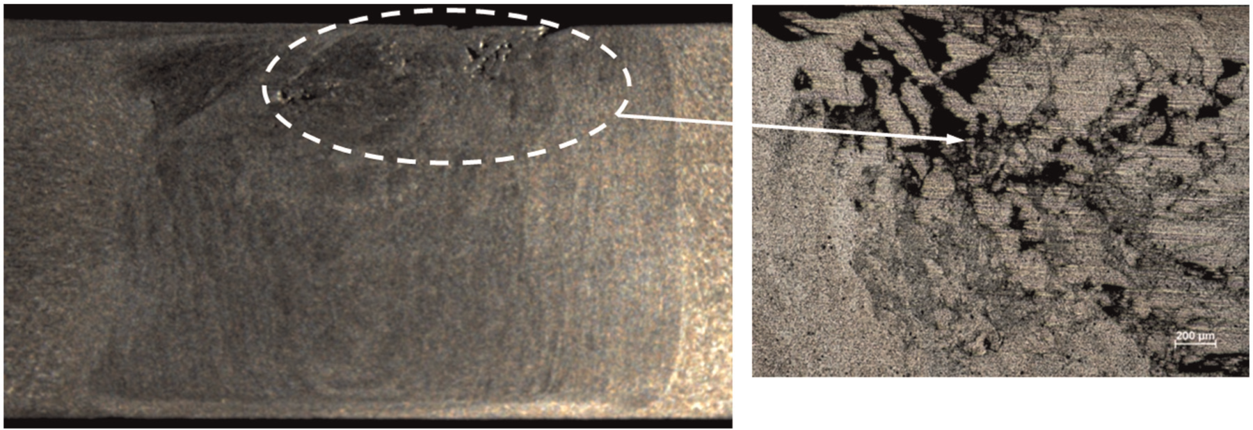
A defect occurred at a tool rotational speed of 1250 r/min and welding speed of 63 mm/min.
Hardness
Figure 7 shows the hardness profile of each weld as a function of distance from the retracting side to the advancing side. The hardness of the base metal is 78 ± 1 HV. Three major conclusions can be drawn from Figure 7. The first is that the hardness in the NZ is similar to that in the TMAZ. The reason for this is that there is a temperature reduction gradient from the NZ to the TMAZ. The second is that the hardness curve shows a symmetric trend on both sides, and the peak hardness is observed at the NZ. This was attributed to the smaller grain that emerged from the dynamically recrystallized grains. The final conclusion is that the hardness values of the HAZ and BM are almost similar. In the literature, 26 it is reported that the 5XXX alloys do not exhibit a HAZ.
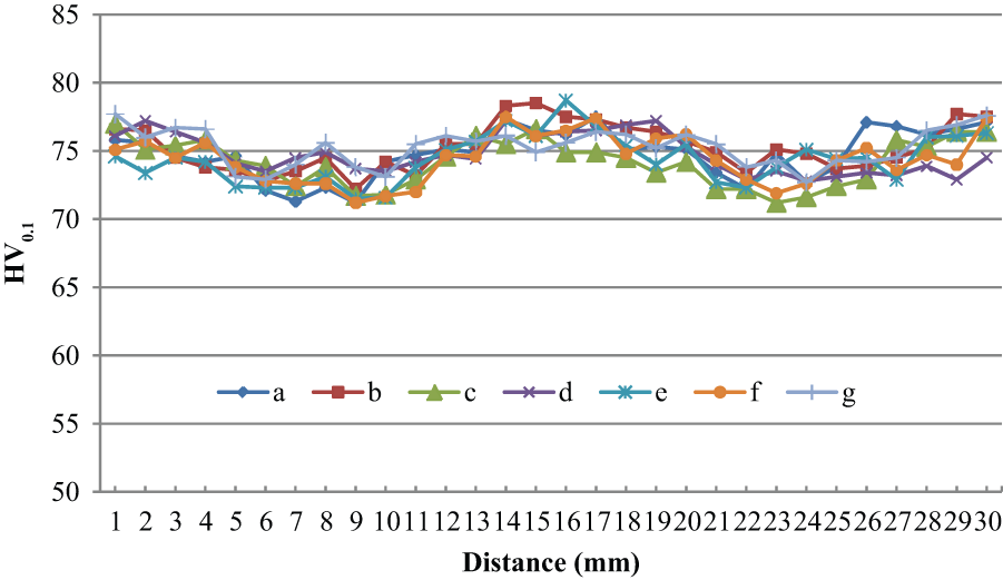
Hardness distribution as a function of distance.
Tensile properties
The welds were also characterized through transverse UTS and ε. The mechanical test results are reported in Table 3. The UTS of the welds decreases with the increase in WS for 1250 r/min. At 800 r/min, while the UTS for 80 mm/min is 289 MPa, for 100 mm/min, the UTS is 287 MPa. It is obvious that there is no notable difference observed with the increase in WS. This result indicates that the grain size does not change at the same rate of change in WS. At 125 mm/min, the UTS showed a tendency to increase. The elongation also shows a similar trend to the UTS, ranging from 9.7% to 11.81%. At 1250 r/min, the elongation decreases with the increase in WS. The percentage of elongation (ε) of welds was found to be from 1.65% to 11.31%. The UTS and ε of the welds made at 800 r/min exhibit higher values than those at 1250 and 1000 r/min. The reduction in UTS at 1250 r/min can be attributed to existing defects like voids in the NZ. The effect of WS on UTS and ε can be summarized as given in the literature,11,12,28,29 and the UTS decreases with the increase in WS. Mrudula et al.’s 30 study also mentions that the decrease in UTS as a function of a higher WS is explained by the decrease in heat input and plastic flow of the material. Over and above this, an investigation was also done at 100 mm/min. The results showed that the UTS and ε decreased with the increase in the TRS.
Weld efficiency is a ratio which expresses the strength of a welded to the strength of the base metal. For this study, the UTS of welds was compared with the UTS of the BM, and the results recorded as the weld efficiency are shown in Table 3. The UTS and ε of the BM are 325 MPa and 17.6%, respectively. The highest weld efficiency was observed at 125 mm/min and 800 r/min as 92%. A remarkable drop (57%) in the UTS was achieved in the weld produced at 100 mm/min and 1250 r/min. This reduction can be attributed to defects in the NZ.
The face bending test results are reported in Table 3. It is clear that the bending strength (σb) values show a similar trend to the results of UTS. Apart from group 1 welds, the other welds were broken without 90° bending.
Fracture surface
The macro-investigation of each weld showed that the welds made at 1250 and 1000 r/min at 100 mm/min have defects, and it is believed that these defects affect the fracture morphology and fracture surface characteristics. In order to determine the fracture surface characteristics, SEM and EDS analyses were done. Therefore, two specimens were selected, one from group 1, which had welds performed at 800 r/min, and one from group 2, which had welds performed at 1250 r/min. In addition, the fracture surface of the specimen at 1000 r/min was analyzed. The fracture surfaces of selected welds are shown in Figure 8. While all the fracture surfaces display dimples, the size and shape of the dimples show differences. Moreover, voids were detected in the surface of the welds made at 1250 and at 1000 r/min at 100 mm/min. However, there are dimple-free flat regions, as can be seen in Figure 8(a), (c) and (d), and a ductile fractured surface can be identified in this figure. Figure 8(f) and (g) shows many defects such as voids, cracks and porosities.
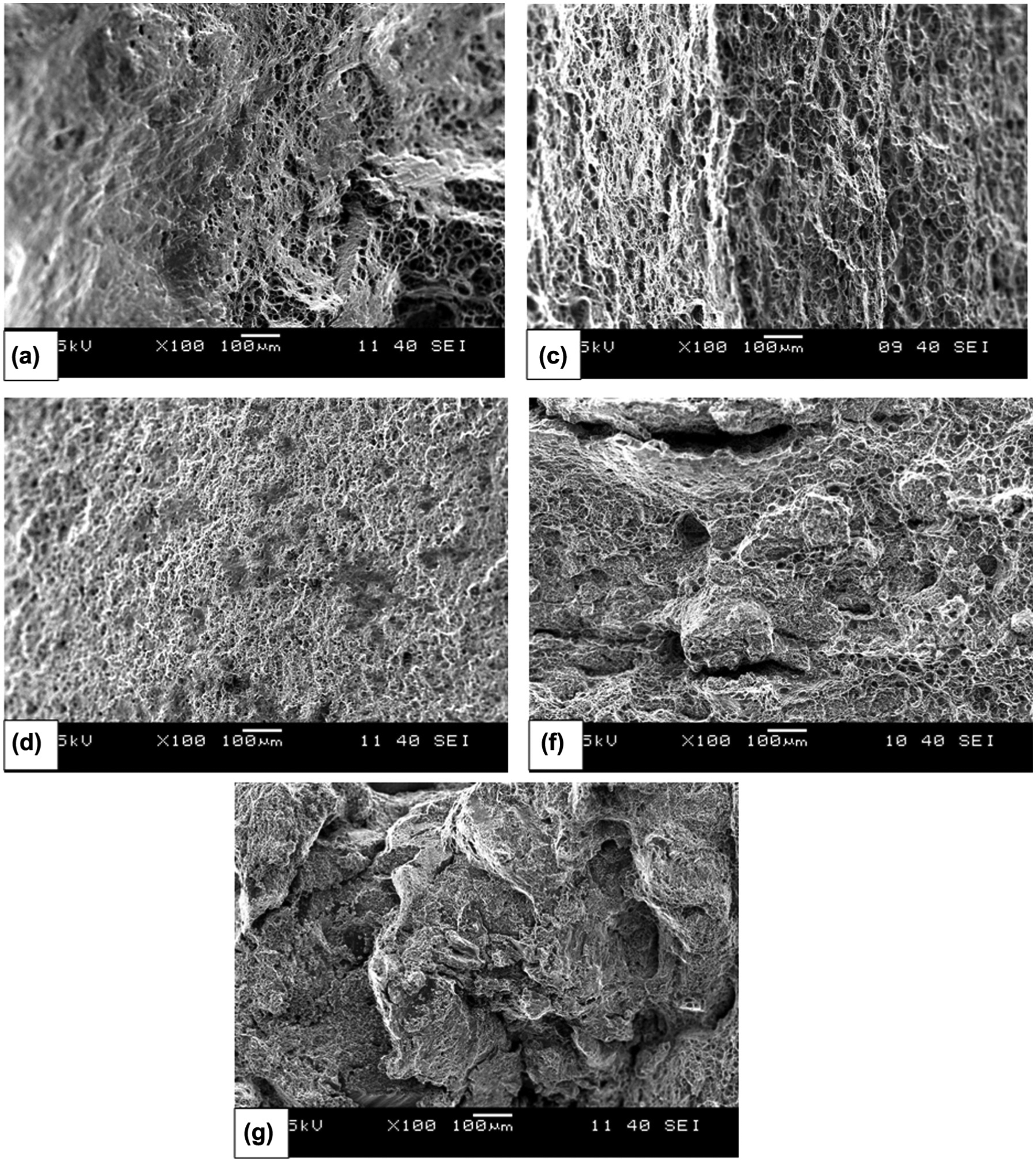
Fracture surfaces after tensile tests while the TRS and WS are equal to (a) 800 r/min and 80 mm/min, (c) 800 r/min and 125 mm/min, (d) 1250 r/min and 40 mm/min, (f) 1250 r/min and 100 mm/min and (g) 1000 r/min and 100 mm/min.
During the investigation of the fracture surface, some second-phase particles were detected in the dimples. To determine the nature of these particles, EDS analysis was done at the points shown in Figure 9(a) and (b). The results of EDS analysis show that the particle in Figure 9(a) is Mg- and Fe- rich, while the structure shown in Figure 9(b) is a Mn- and Fe-rich material. The other particle in the dimple, as shown in Figure 9(d), is Mn, Fe and Si rich, while the light gray small particle shown in Figure 9(c) is a Mn-rich structure. The main precipitated particles of AA 5083 are Al6Mn, MgxSi and Alx(Fe,Mn)ySiz.11,13,29,31 The observed intermetallic particles are consistent with the literature.
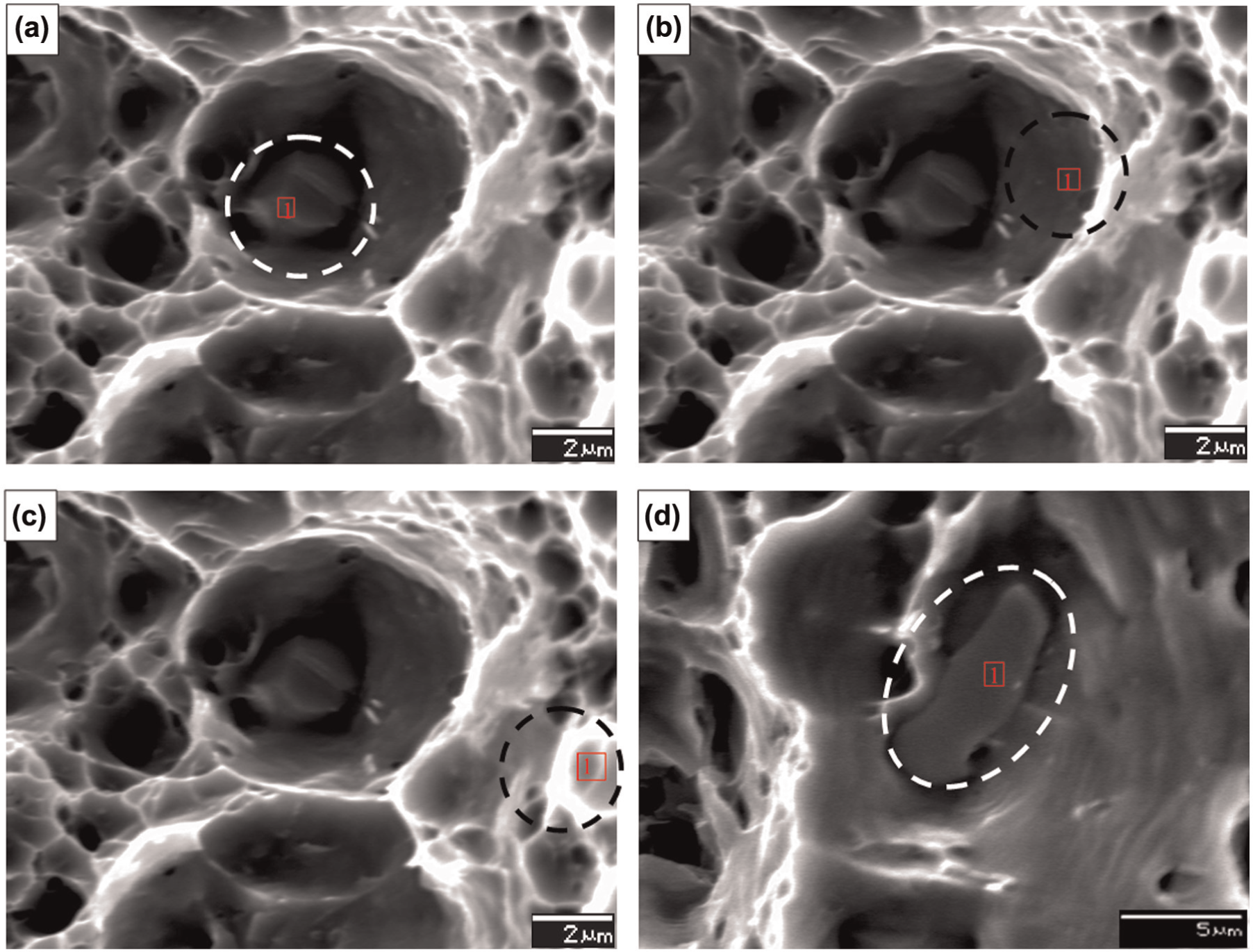
Second-phase particles in the dimples.
Conclusion
This study investigated the effect of associating a triangular pin with FSW parameters on the UTS, ε, hardness and microstructure. A series of experiments were performed, and the following conclusions were drawn.
All the microstructures of NZ exhibit fine equiaxed grains. However, the grains in the TMAZ are elongated along the pin rotation direction. Additionally, the grain sizes of the BM and HAZ were almost the same. This is consistent with the hardness results.
From the analysis of the fractured surface, some second-phase particles were detected. EDS analysis indicated that some of these are Mn-, Fe- and Si-rich particles, some are Mn- and Fe-rich particles and the others are Mg- and Fe-rich particles.
The highest hardness was achieved at the NZ. The gradient in the hardness distribution is similar for all weld cases. The difference is very small, which shows that the effect of the weld parameters does not create a major transformation in the size of grains.
While the UTS and ε increased with the increase in WS at 800 r/min, the opposite trend was observed for 1250 r/min. In addition, the effect of WS on both UTS and ε is significant because many defects occurred with the increase in WS. The reduction in UTS and ε is attributed to existing defects. The highest UTS and ε are achieved at 800 r/min and 125 mm/min. This weld case has the highest weld efficiency. Furthermore, apart for the defective welds, the UTS varies between 299 and 287 MPa. For these weld cases, the weld efficiency varies between 88% and 92%. These results are consistent with the hardness results. In the existing weld cases, a comparison was done at 100 mm/min, and it was observed that the UTS and ε decreased with the increase in TRS.
Footnotes
Declaration of conflicting interests
The authors declare that there is no conflict of interest.
Funding
This study was fully supported by Dokuz Eylul University under project no. 2011.KB.FEN.045.