
Abstract
In order to achieve nanometer accuracies, the low vibration of air spindle and air table is vital. Number and size of air pockets in air spindles and air tables are important parameters in nanomachining vibrations. In this article, rotational speed as well as these parameters has been studied. Three levels are selected for each parameter and, in total, 27 experiments have been committed. Also, in this work, air pockets were rectangular. In this study, rotor considered externally which rotates about stator. Experiments were conducted with the help of a lathe machine. For vibration measurements, the VibroTest 60 was used. The results were analyzed using design of experiment method. Experimental results show that the air spindle with two air pockets with 200 mm2 area at a low rotational speed has minimum vibrations.
Introduction
These days, high-precision products are widely required with job-shop type production and small batch production in the fields of manufacturing and machining. 1 To this end, high-speed and high-precision air spindles are widely used as the components of hard disk drives for computers, dental drills and machining of polygon mirrors for laser scanners because high-speed rotation with small heat generation is possible for air spindles due to the low viscosity of the air lubricant. It also gives a noise-free, smooth running machine and does not add to the sound and vibration levels of the machine in the way that high-speed ball bearings do. Before entering the air into the air gap, it goes through a pocket, which reduces instabilities such as air hammer.
Air spindle and drive systems are important parts of ultra-precision machines, because the spindle motion error will have significant effect on the surface quality and accuracy of machined components. Spindles in ultra-precision machines have high motion accuracy and rotational speed.2,3 Different researches have been committed on the characteristics of air bearings and their effect on performance. In 1985, Boffey et al. 4 investigated air pocket depth variations on air bearing stiffness, load capacity and flow rate. In 2000, Stout and Barrans 5 presented a study in design of aerostatic bearings for application to nanometer resolution manufacturing machine systems. In 2002, Chen and Lin 6 have analyzed static behavior and dynamic stability of grooved rectangular aerostatic thrust bearings with X-shaped grooves. In 2002, Chen et al. 7 investigated an arc-type aerostatic bearing with axial straight and the circumference arc-type grooves. In 2009, Chen et al. 8 investigated the effect of air pockets on the stability of aerostatic rotor bearing system. They studied the effects of feed holes and their number and position on the stability of aerostatic spindle using nondimensional Reynolds equation that was derived from Navier–Stokes and continuity equations. In 2002, Fan and Ho from Taiwan and Mou from Arizona presented an aerostatic air bearing system with multiple microholes. 9 They have prototyped multiple microholes instead of porous-type air bearing. Using porous material or multiple microholes will help in constant pressure distribution in the air gap. In 2003, Noguchi and Miyaguchi 10 proposed an evaluation method of radial accuracy for hydrostatic air spindles considering radial movement of the rotating center. In 2004, Park and Kim 11 studied, analytically and experimentally, the stability of the spindle system using a new type of slot-restricted gas journal bearings. In 2009, Hirayama et al. 12 optimized the groove dimensions in herringbone-grooved journal bearings for improved repeatable run-out characteristics. In 2010, Chen et al. 13 theoretically and experimentally analyzed a compound restrictor circular gas bearing with three straight and arc shallow grooves machined on the bearing surface, along which the supplied gas flows, and they reported same results for air film thickness effects.
In previous researches, the air pocket parameters were selected for air bearing stiffness, load capacity and flow rate analysis, and air bearing vibrations were not investigated. In this study, the air pocket parameters, including number, size and rotational speed, are selected for investigating air spindle radial vibrations. The air pocket shape in this study varied with the parameters in previous researches and selected as rectangle.
Design of air spindles
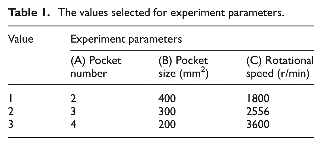
Some air pocket parameters, including air pocket shape, number, size and depth, affect air spindle vibrations. In this study, the number and size of air pocket are investigated as air pocket parameters. Table 1 shows the values for each parameter used for investigation. These values have been selected randomly and in accordance with manufacturing and experimental limits.
The values selected for experiment parameters.
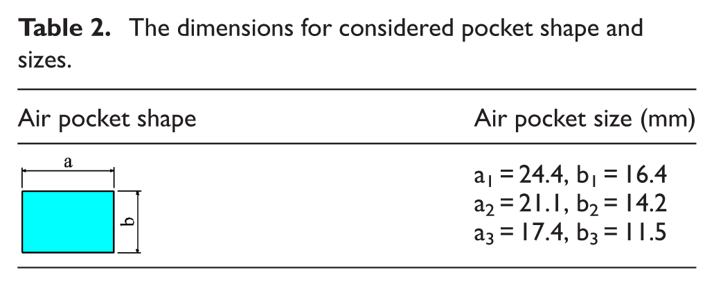
For better air distribution in the air gap, the rectangular air pockets have been selected for air pocket shape. Also, air pocket depths are constant, and the depth for all air pockets equals 3 mm. The dimensions for considered pocket shape and sizes are listed in Table 2.
The dimensions for considered pocket shape and sizes.
As shown in Table 1, the numbers for air pockets are selected as 2, 3 and 4. Stainless steel was selected for rotor and bush of stator materials and brass for shaft of the stator. The air gap between the rotor and stator was selected as 25 µm. For mounting the air spindle on the lathe cross slide, a base was designed and bolted on it. The number of air pockets on all stators was located at equal angular distances around the stator. Figure 1 shows one set of manufactured stators and rotor.
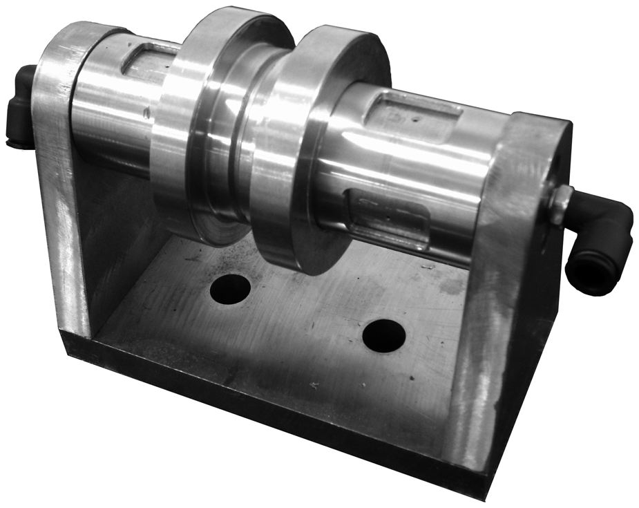
One set of manufactured stators and rotor.
Experimental setup
Figure 2 shows the experimental setup. Vibration measurement was set on VibroTest 60. Displacement sensor was an IN-085. Mounting magnet was set for sensor installation. A 1.5-mm-thick feeler was employed for set up of sensor with respect to the rotor surface. Rotational speeds set on the lathe machine included 500, 710 and 1000 r/min and experimental rotational speeds were set as 1800, 2556 and 3600 r/min, respectively. The test runs were done randomly.
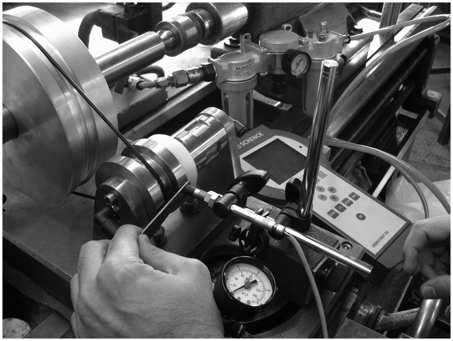
Experimental setup.
Results and discussion
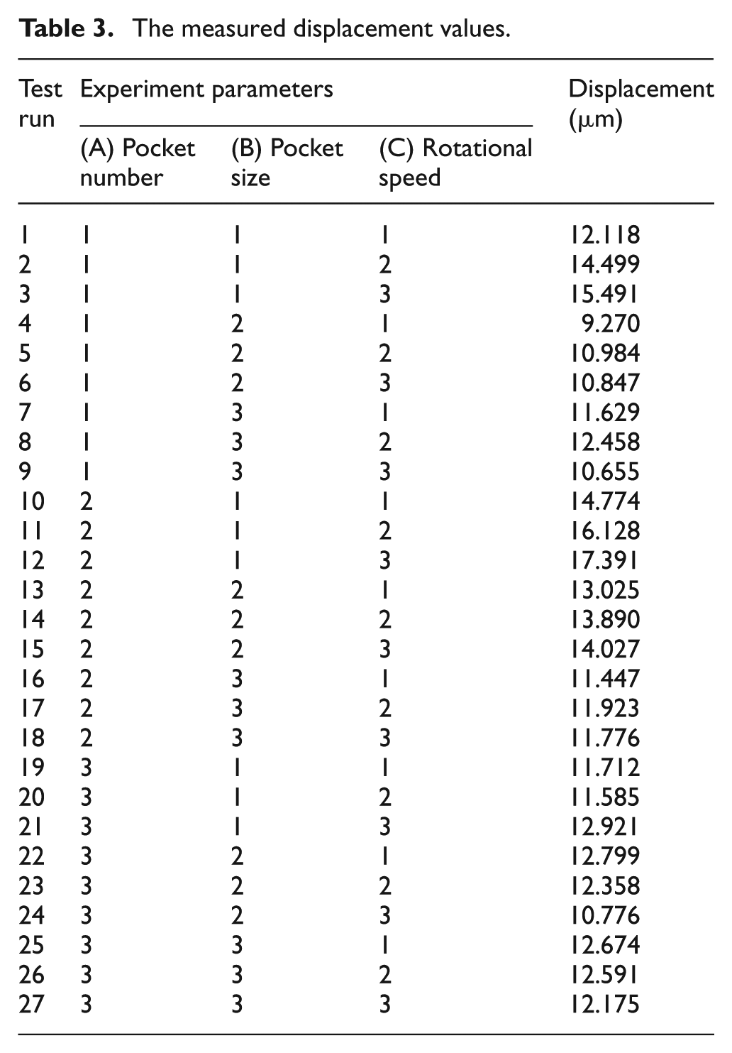
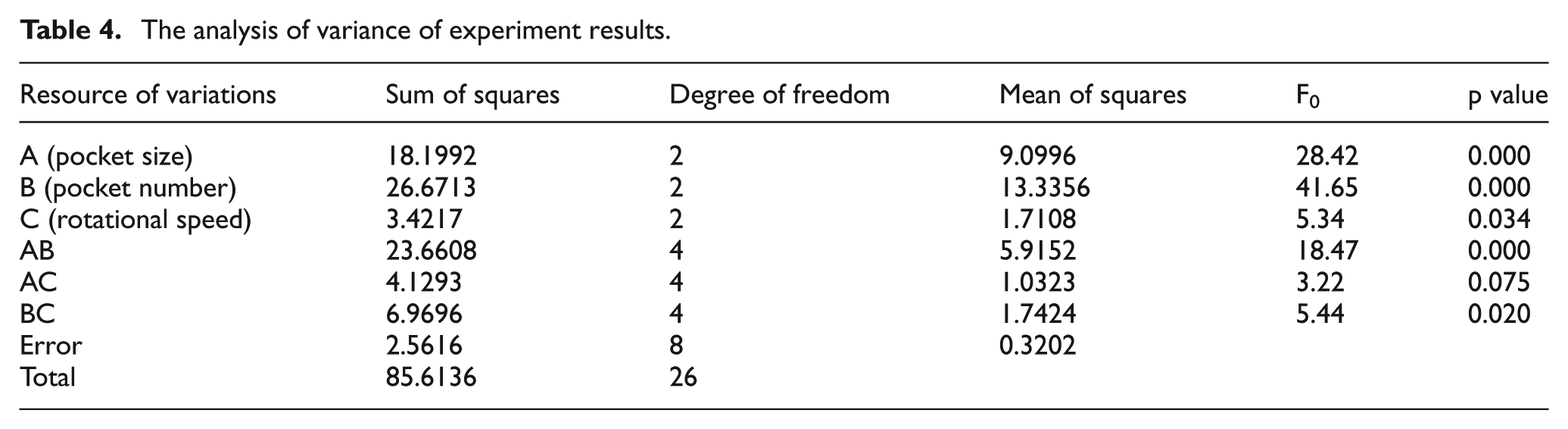
Measured displacement values for the location shown in Figure 2 are listed in Table 3. For analyzing measured values, the design of experiment (DOE) method is employed. The analysis of variance (ANOVA) for these results is shown in Table 4. According to the ANOVA results, all studied parameters are significant in air spindle vibrations. In order to figure out the parameter levels in which air spindle vibrations are minimized, the main effect and interaction effect plots of these parameters have been plotted. The normal probability plot of the residuals for air spindle vibrations is shown in Figure 3. Figures 4 to 6 show plots of main effects of air pocket number, pocket size and rotor rotational speed, respectively.
The measured displacement values.
The analysis of variance of experiment results.
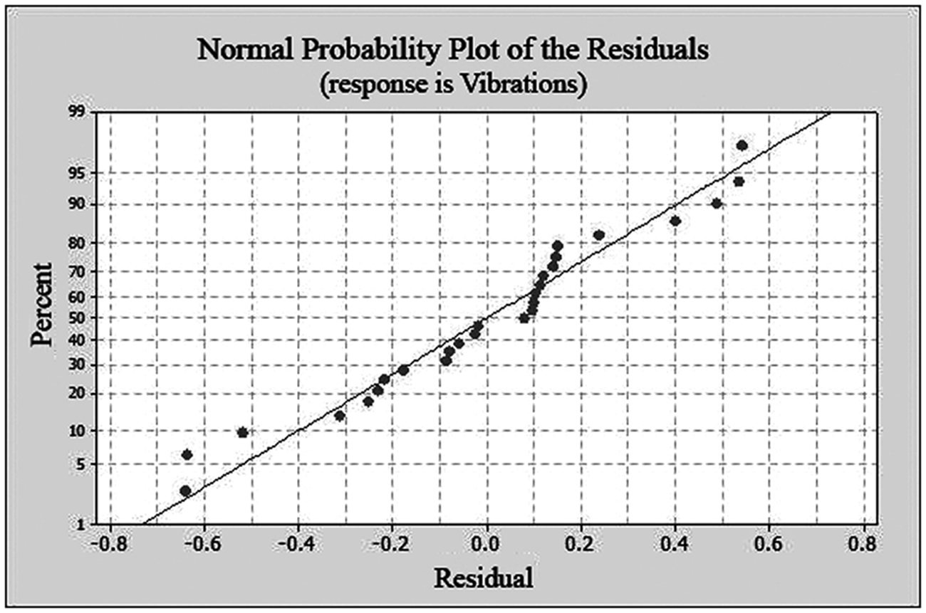
The normal probability plot of the residuals for air spindle vibrations.
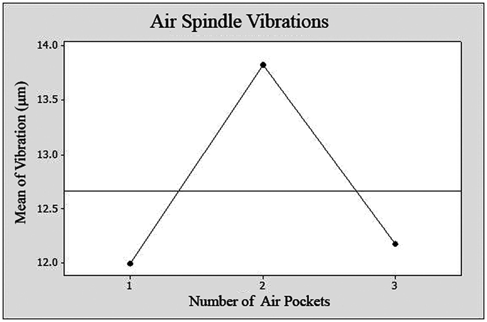
The main effect of air pocket number on air spindle vibrations.
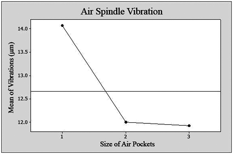
The main effect of air pocket size on air spindle vibrations.
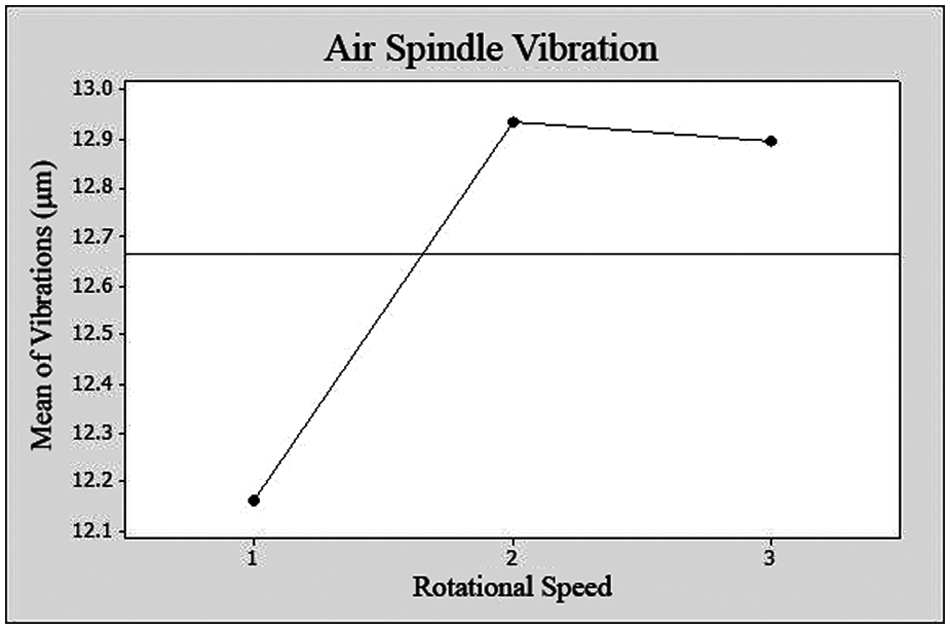
The main effect of rotor rotational speed on air spindle vibrations.
As shown in Figure 3, the air spindle displacement values have normal distribution. From Figure 4, it can be seen that the air spindles with two air pockets have minimum vibrations. As shown in Figure 5, air pocket size of 200 mm2 shows minimum vibration. Also, from Figure 6, it can be seen that air spindles in lowest rotational speed have minimum vibration. Figures 7 to 9 show interaction effect plots of air pocket number and size, air pocket number and rotational speed, and air pocket size and rotational speed on air spindle vibrations, respectively.
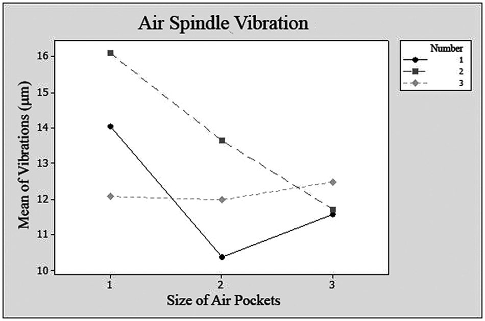
The interaction effect plot of air pocket number and size on air spindle vibrations.
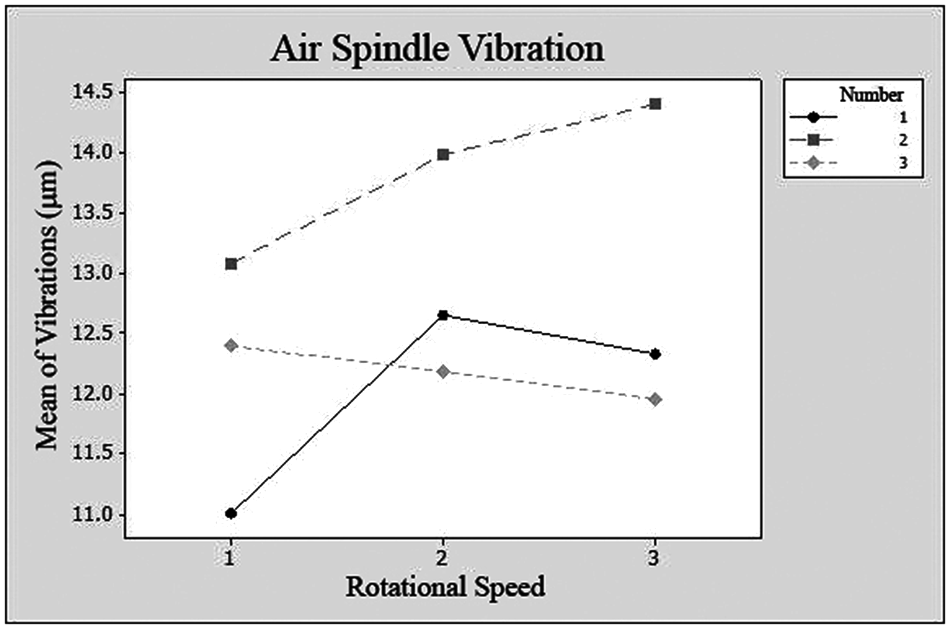
The interaction effect plot of air pocket number and rotational speed on air spindle vibrations.
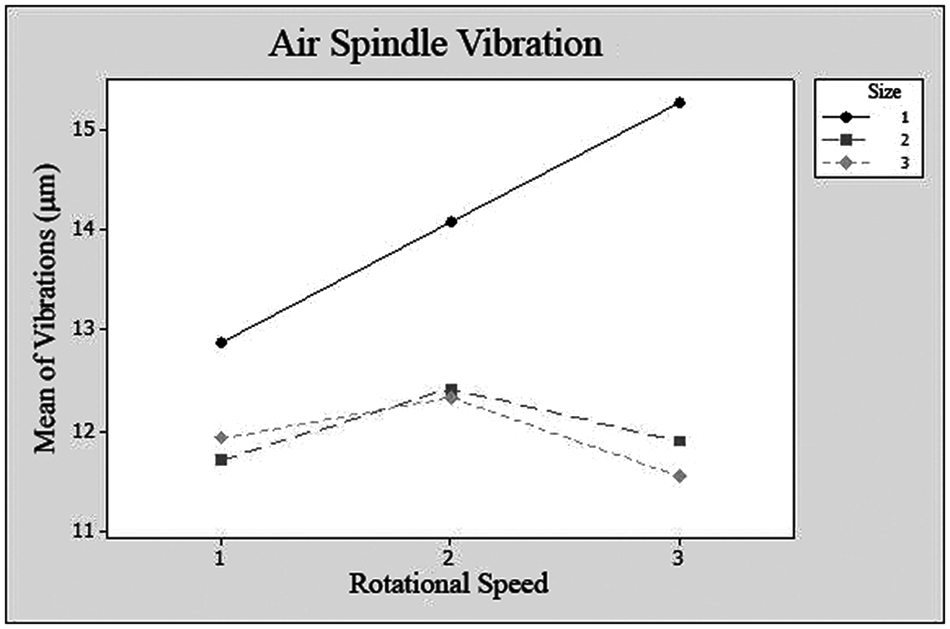
The interaction effect plot of air pocket size and rotational speed on air spindle vibrations.
From Figure 7, the spindle with two pockets and area of 300 mm2 has minimum vibrations. From Figure 8, it can be seen that the spindle with two air pockets at rotational speed of 1800 r/min shows minimum vibration. Also, from Figure 9, it can be seen that the spindle with pocket size of 200 mm2 at 3600 r/min rotational speed has minimum vibration.
Conclusion
From DOE, it can be concluded that in air spindle vibrations, all estimated parameters are significant.
Air spindle with two air pockets and air pocket size of 200 mm2 at lowest rotational speed has minimum vibrations.
In higher rotational speeds, the air spindles with four air pockets and air pocket size of 200 mm2 have minimum vibrations.
The air spindle with three air pockets and air pocket size of 400 mm2 at highest rotational speed has maximum displacement.