
Abstract
In this study, factors that affect air spindle vibrations have been investigated experimentally. In order to achieve nanometer accuracies, the low vibration of air spindle is vital. Shape, size, depth, number of air pockets, and rotational speed of air spindles are important parameters influencing nanomachining vibrations. A total of 3 levels are selected for each parameter and in total 243 experiments have been performed. In this study, the rotor is considered externally which rotates about a central stator. Experiments were committed by the help of a lathe machine. For vibration measurements, the VibroTest 60 has been used. Results have been analyzed using the Design of Experiment method. From the results, it has been analyzed that the air spindle with 2 circular/rectangular air pockets and with 300 mm2 area and 3 mm depth at a low rotational speed has minimum vibrations.
Introduction
The need to improving quality and productivity in precision products drives the need of machine tool spindles with higher performance in terms of stiffness, resolution, accuracy, and load capacity. Performance improvement is generally achieved through innovation in spindles and machine structures. In particular, spindles are the heart of the machine tools, and are the focuses of designers seeking to increase machine tool performance.
These days high-precision products are widely required with job shop type production and small batch production in the fields of manufacturing and machining. 1 High-speed and high-precision air spindles are widely used as the components of hard disk drives for computers, dental drills, and machining of polygon mirrors for laser scanners because high-speed rotation with small heat generation is possible for air spindles due to the low viscosity of the air lubricant. It also gives rise to a noise-free and smooth running, and does not add to sound and vibration levels of the machine in the way that high-speed ball bearings do. Before entering the air gap, it goes through a pocket, which reduces instabilities such as air hammer.
Air spindle and drive systems are important parts of ultra precision machines, because the spindle motion error will have significant effect on the surface quality and accuracy of machined components. Spindles in ultra precision machines have high motion accuracy and rotational speed.2,3
Different researches have been conducted on the characteristics of air bearings and their effect on performance. In 1985, Boffey et al. 4 investigated the effects of air pocket depth variations on air bearing stiffness, load capacity and flow rate. In 2000, Stout and Barrans 5 presented a study on the design of aerostatic bearings for application to nanometer-resolution manufacturing machine systems. In 2002, Chen and Lin 6 have analyzed the static behavior and dynamic stability of grooved rectangular aerostatic thrust bearings with X-shaped grooves. In 2002, Chen et al. 7 investigated an arc-type aerostatic bearing with straight axial and the circumference with arc-type grooves. In 2009, Chen et al. 8 investigated the effect of air pockets on aerostatic rotor-bearing system stability. They studied the effects of feed holes and their number and position on aerostatic spindle stability by using the non-dimensional Reynolds equation, which was derived from Navier–Stokes and continuity equations. In 2002, Fan and Ho from Taiwan and Mou from Arizona presented an aerostatic air bearing system with multiple micro-holes. 9 They prototyped multiple micro-holes instead of porous-type air bearing. Using porous material or multiple micro-holes will help in maintaining constant pressure distribution in air gap. In 2003, Noguchi and Miyaguchi 10 proposed an evaluation method of radial accuracy for hydrostatic air spindles considering radial movement of the rotating center.
In 2004, Park and Kim 11 studied, analytically and experimentally, the stability of spindle system using new type of slot-restricted gas journal bearings. In 2009, Hirayama et al. 12 optimized the groove dimensions in herringbone-grooved journal bearings for improved repeatable run-out characteristics. In 2009, Chen et al. 8 presented a comparison of the stability of the rotor-aerostatic bearing system compensated by orifices and inherences. In this study, the influences of the number and the locations of air entries on the aerostatic bearing are also estimated. In 2010, Chen et al. 13 theoretically and experimentally analyzed a compound restrictor circular gas bearing with three straight and arc shallow grooves machined on the bearing surface, along which the supplied gas flows, and they reported same results for air film thickness effects.
In 2012, Akhondzadeh and Vahdati 14 investigated the effect of size and number of rectangular air pockets on air spindle vibrations. In their research, air pockets with minimum number and size showed minimum vibrations. In 2012, Akhondzadeh and Vahdati 15 also investigated the effect of shape and depth of air pockets on air spindle vibrations in ultra precision machining. They reported that the air spindle with a rectangular-shaped air pocket at low rotational speed has minimum vibrations.
In previous researches, except those by Akhondzadeh and Vahdati,14,15 the air pocket parameters that have been selected for analysis were air bearing stiffness, load capacity, and flow rate, whereas air bearing vibrations have not been investigated. In the present study, the air pocket parameters such as shape, size, depth, number, and shaft rotational speed have been selected for investigating the air spindle radial vibrations. In Akhondzadeh and Vahdati,14,15 the effects of these parameters have been investigated separately: in one study, 14 the effects of size and number of air pockets have been studied and in the other, 15 the shape and depth have been analyzed.
Air bearing equations
For an aerostatic journal bearing, as shown in Figure 1(a), air is supplied from an externally pressurized source and passes through entries with orifice compensation as shown in Figure 1(b), which are located in double rows about the asymmetric plane and evenly around the circumference of the bearing.
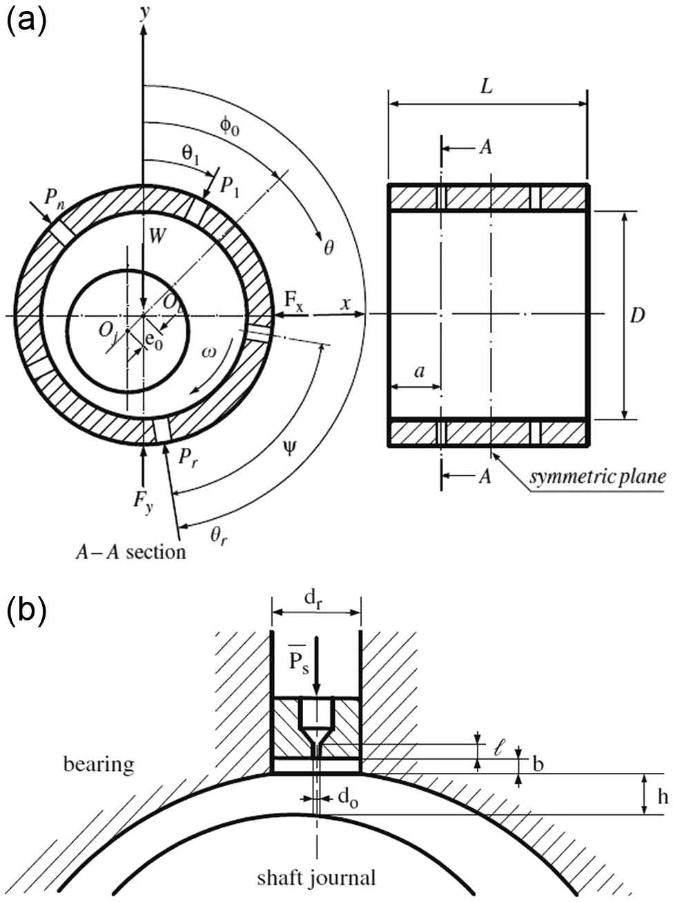
Configurations of (a) an aerostatic bearing with double-array entries compensated by (b) orifice restriction.
Assuming the air at the bearing clearance as perfect gas, which is compressible, isothermal, and has laminar flow, the non-dimensional Reynolds equation could be derived from the Navier–Stokes and continuity equations. In the two-dimensional Cartesian coordinates, it may be shown as
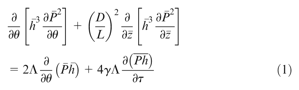
where D and L are the bearing diameter and length, P and h are the non-dimensional pressure and thickness of film, y and z are the angular and axial coordinates of bearing, respectively, T is non- dimensional time, Λ is bearing number and γ is whirl ratio.
Design of air spindles
Some air pocket parameters affect air spindle vibrations, including air pocket shape, number, size, and depth. In this study, all of these parameters are investigated as air pocket parameters. Table 1 shows the values of each parameter used for investigation.
The values selected for experiment parameters.
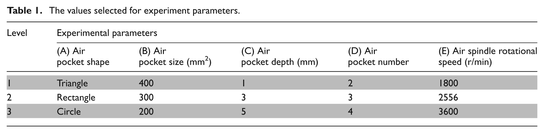
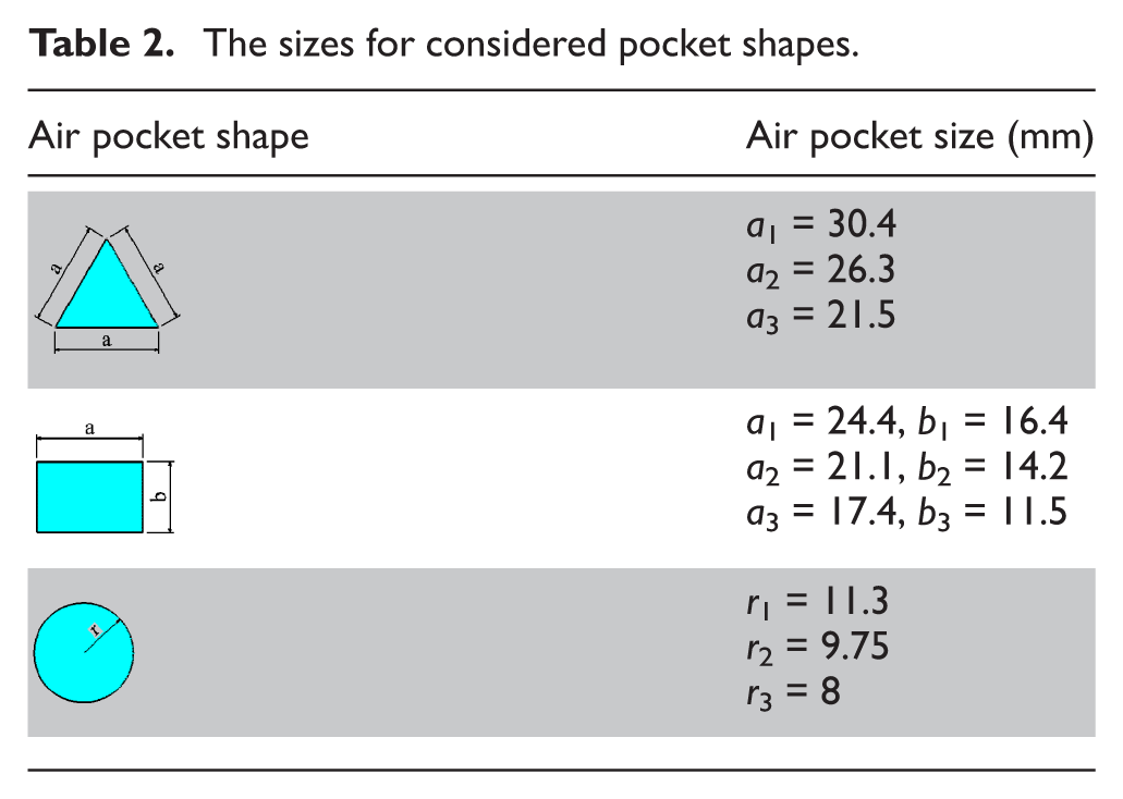
The selected air pocket shapes include circular, rectangular, and triangular with air pocket depths equal to 1, 3, and 5 mm, respectively. Sizes of air pockets have been designed in order to have areas of 200, 300, and 400 mm2, respectively. The details of selected dimensions have been listed in Table 2. As shown in Table 1, the numbers for air pockets have been selected as 2, 3, and 4. These values have been selected randomly and are in accordance with manufacturing and experiment limits.
The sizes for considered pocket shapes.
For relief in parts manufacturing and ease of vibration measurements, the rotor is considered externally as it rotates about the stator. Also, stators are designed as two separate parts, shaft of stator and bush of stator, which the shaft of stator will assemble in bush of stator after manufacturing. Stainless steel is selected for the rotor and bush of stators and brass for the shaft of stators. The difference between the internal diameter of rotor and the external diameter of stator is 50 µm; in other words, the air gap is 25 µm.
The lathe machine is selected for performing experiments and obtaining spindle rotational motion. Therefore, to reach considered rotational speeds, the ratio of drive pulley diameter to rotor diameter is considered as 3.6.
For transmission of the rotational speed from drive pulley to rotor and to maximize the parallelism of drive pulley axis and rotor axis for maximum rotor equilibrium, the O-ring is selected as belt. Also, the air pressure is considered equal to 1.5 bar, and the air feeding orifice diameter selected as 1 mm.
For mounting the air spindle on the lathe cross slide and performing experiments, a base was designed and bolted on this cross slide. Air pockets on all stators were located at equal angular positions around the stator.
Manufacturing of air spindles
The parts that were designed previously are manufactured by various production processes. The machining processes include boring and facing of steel bushes, milling of pockets by computer numerical control (CNC)-mills, filing, brass shafts facing, turning and drilling, assembling brass shafts into steel bushes, 1 mm feeding orifice drilling, holes threading, grinding of external surfaces of stators and internal surface of rotor by cylindrical grind, and finishing of stators and rotor surfaces by sand.
Figure 2 shows the stators manufactured for all the experiments. A set of the manufactured stator and rotor is shown in Figure 3.
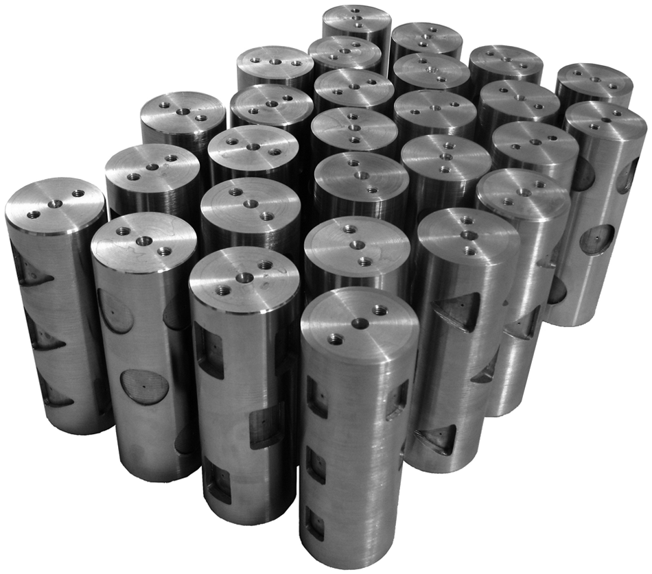
Manufactured stators for all experiments.
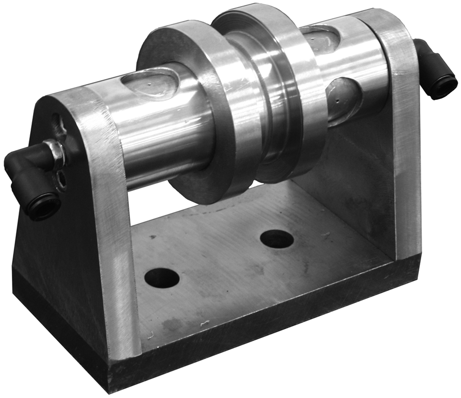
The manufactured spindle set.
Experimental setup
Figure 4 shows the experimental setup.
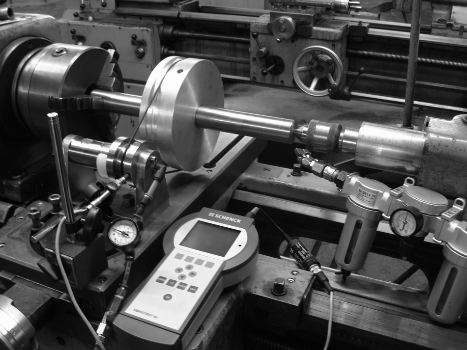
Experimental setup.
The test rig includes the following:
Air spindle and base—that were manufactured previously;
Lathe machine—for performing experiments on its cross slide, which disassembled its compound slide rest and mounted test base on cross slide;
Drive pulley that transmits the lathe work holder rotational motion to rotor;
Humidity and oil absorber—for absorbing water, oil, and other particles in compressed air due to the working of the compressor and preventing them from entering the air gap;
Pressure regulator and pressure gauge—for setting desirable air pressure value and assurance of air pressure on stator entrance, respectively;
Air hose—for transmitting compressed air from compressor to air spindle;
O-ring—as belt that transmits rotational motion from drive pulley to rotor;
Air compressor—for providing compressed air;
Vibration measurement set—that contains VibroTest 60 for vibration measurement, displacement sensor IN-085 for vibration sensing, mounting magnet for sensor installation, and 1.5 mm thick feeler for the setup of sensor with respect to rotor surface.
The VibroTest 60 setup that must be performed vibration measurement includes the following:
Sensor type: IN-085;
Measurement amplitude: Peak (p);
Measurement unit: micrometer (µm);
High and low pass frequencies: 10–1000 Hz.
Vibration measurement was set on VibroTest 60. The mounting magnet was set for sensor installation. A 1.5-mm-thick feeler was employed for setup of sensor with respect to the rotor surface.
Rotational speeds on the lathe machine were set at 500, 710, and 1000 r/min, and therefore, using ratios of 1:3.6 for pulleys, the experimental rotational speeds were 1800, 2556, and 3600 r/min, respectively. Figure 5 shows the VibroTest 60 setups.
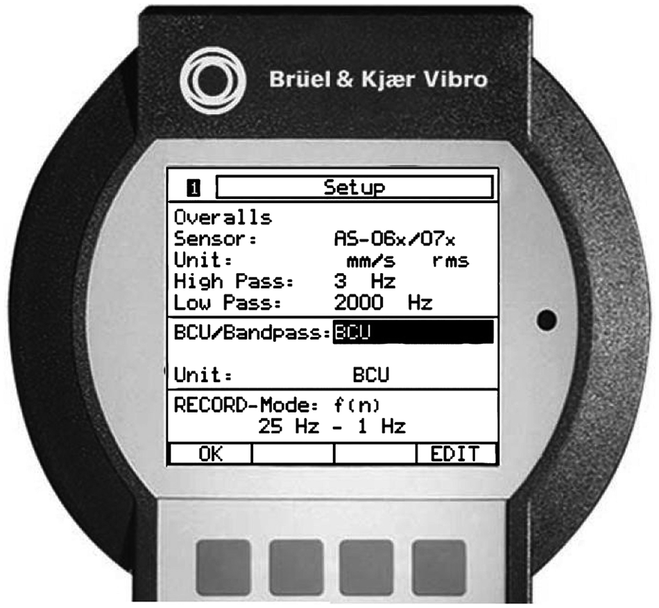
Vibrotest 60 setups.
Results and discussion
The resolution of measured vibrations was in nanometer range (0.001 µm), that is, in one measured vibration, for example, it is equal to 9.270 µm for an air spindle with two 300 mm2 rectangular air pockets with 3 mm depth at 1800 r/min rotational speed.
For analyzing measured values, the design of experiments (DOE) method was employed. The analysis of variance (ANOVA) for these results is shown in Table 3. The accuracy of measured values in this experiment was 1 nm or 0.001 µm.
The analysis of variance of experiment results.
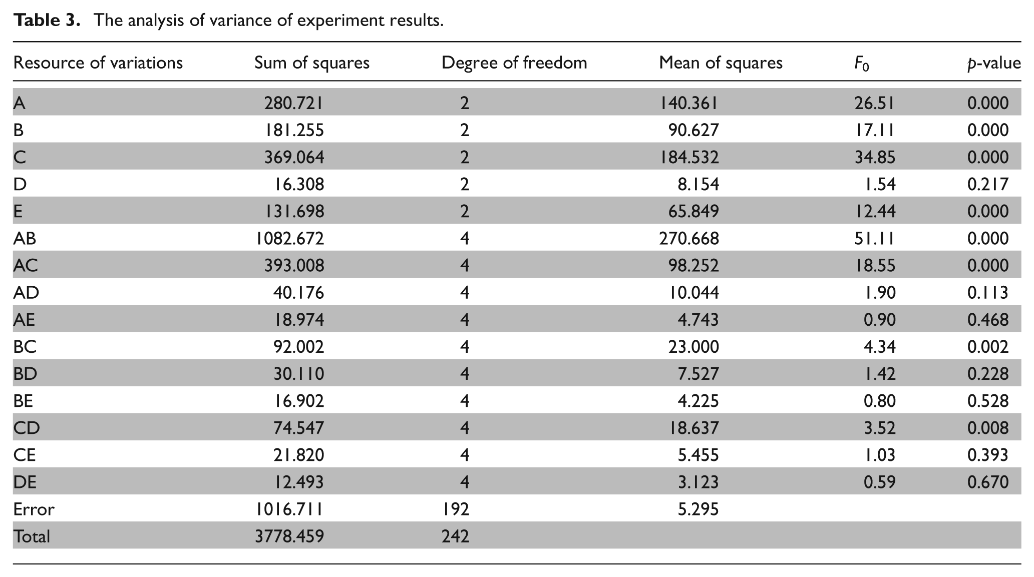
According to ANOVA results, all studied parameters significantly affect air spindle vibrations. In order to figure out the parameter levels in which air spindle vibrations are minimized, the main effect and interaction plot of these parameters have been plotted.
The normal probability plot of the residuals for air spindle vibrations is shown in Figure 6. Figures 7–11 show the plots of main effects of air pocket shape, size, depth and number, and the rotor rotational speed, respectively.
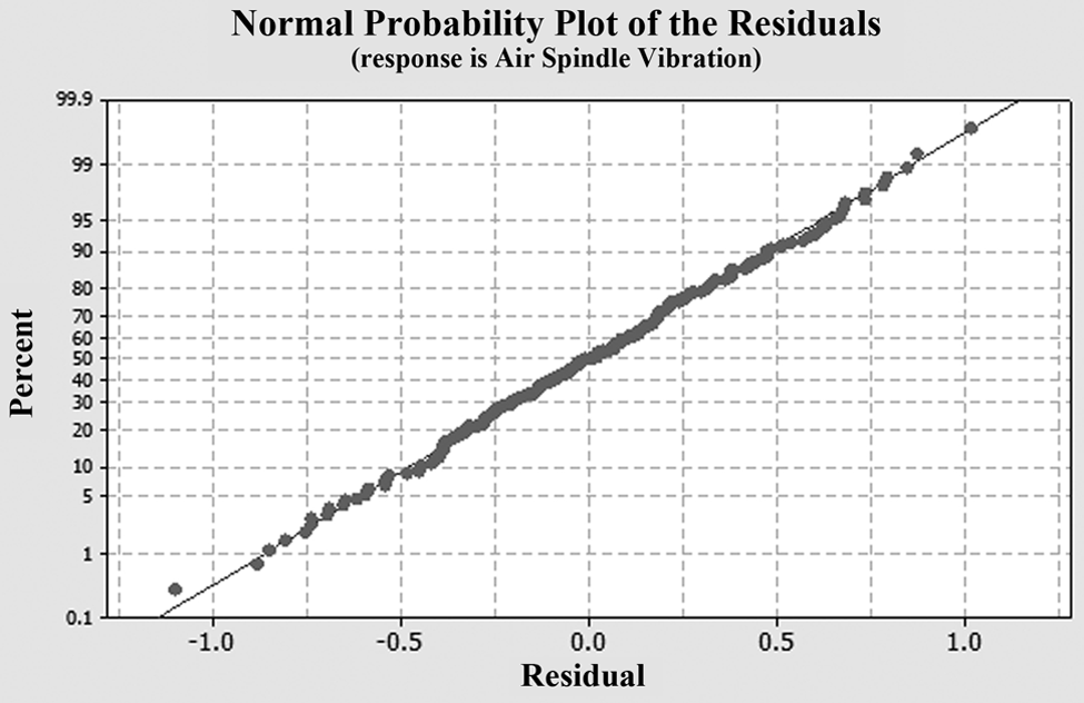
The normal probability plot of the residuals for air spindle vibrations.
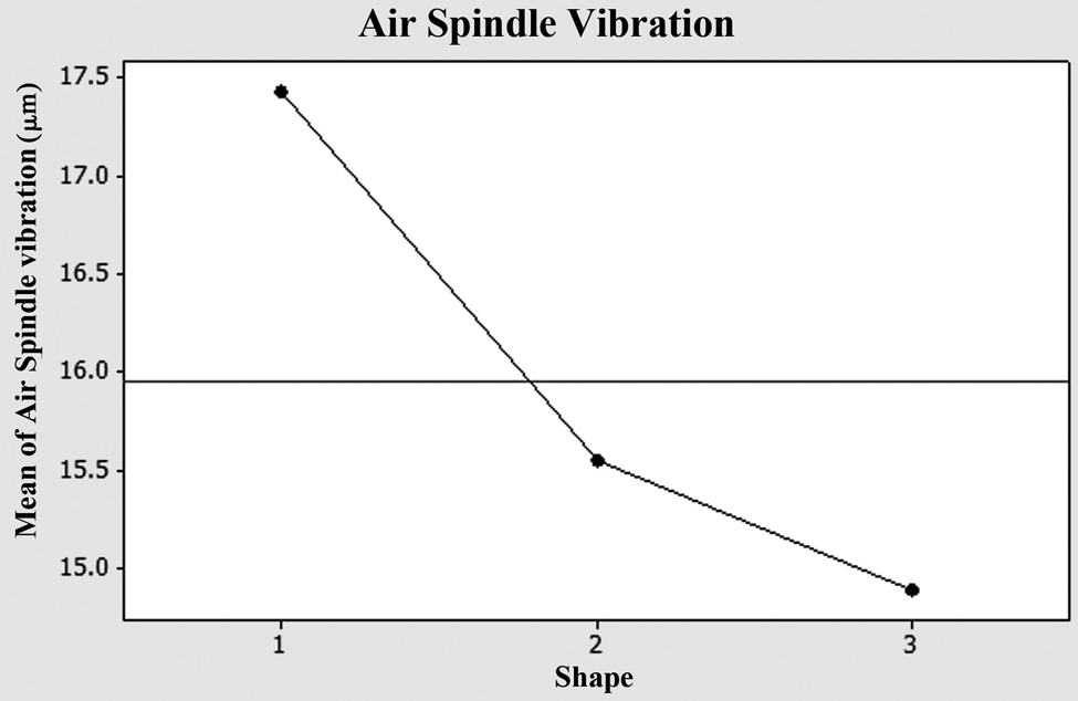
The main effect of air pocket shape on air spindle vibrations.
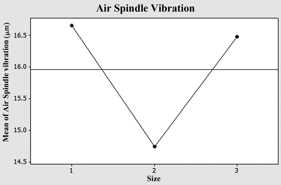
The main effect of air pocket size on air spindle vibrations.
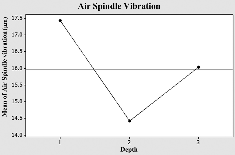
The main effect of air pocket depth on air spindle vibrations.
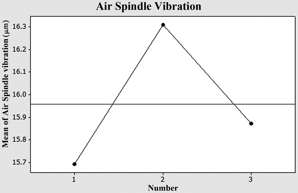
The main effect of air pocket number on air spindle vibrations.
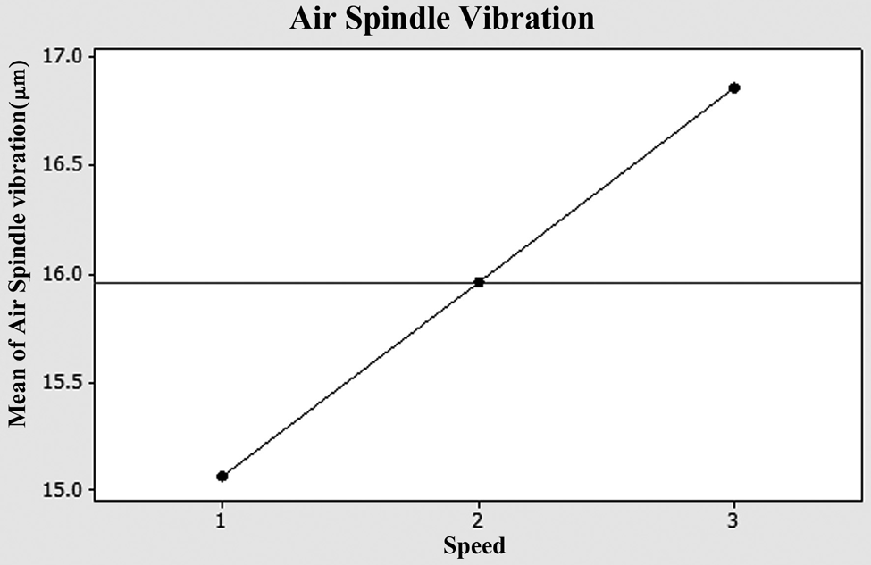
The main effect of rotational speed on air spindle vibrations.
Figure 6 shows that the air spindle displacement values have normal distribution. From Figure 7, it is seen that the air spindles with circular air pockets have minimum vibrations. Figure 8 shows that a value of 300 mm2 of air pocket size shows minimum vibration. In Figure 9, air pockets with 3 mm depth show minimum vibrations. Figure 10 shows that the air spindles with two air pockets have minimum vibrations. Also, from Figure 11, it is seen that air spindles in lowest rotational speed have minimum vibration and air spindle vibrations increase if rotational speed increases.
Figures 12 –21 depict the plots showing the effect of interaction between air pocket shape and size, air pocket shape and depth, air pocket shape and number, air pocket shape and rotational speed, air pocket size and depth, air pocket size and number, air pocket size and rotational speed, air pocket depth and number, air pocket depth and rotational speed, and air pocket number and rotational speed on air spindle vibrations, respectively.
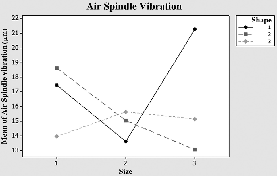
The plot showing the effect of interaction between air pocket shape and size on air spindle vibrations.
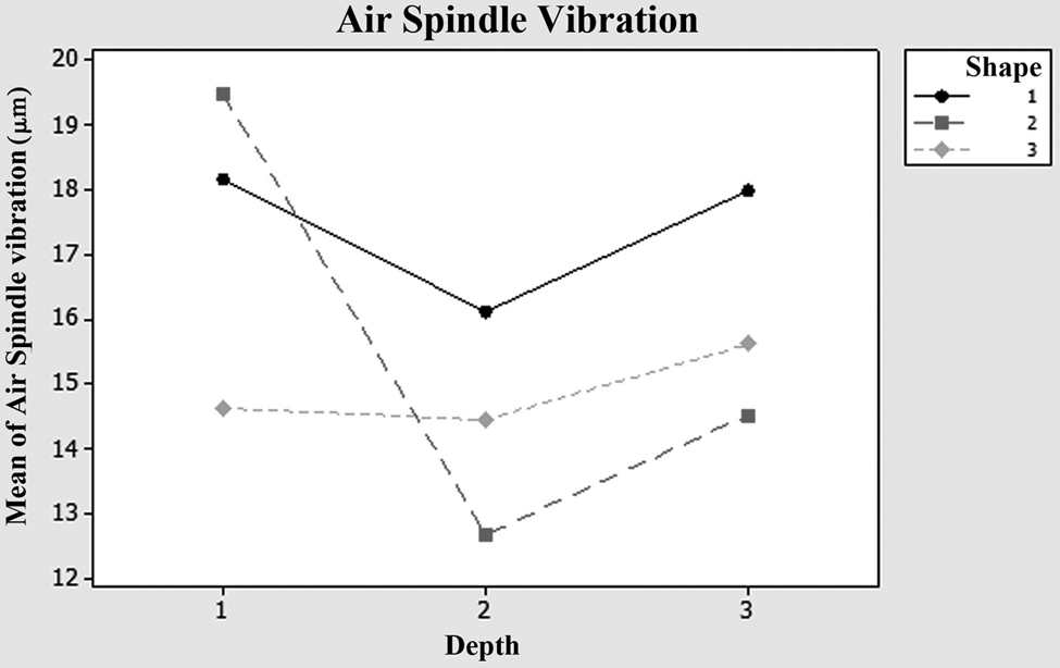
The plot showing the effect of interaction between air pocket shape and depth on air spindle vibrations.
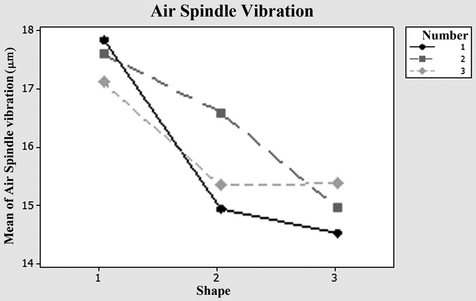
The plot showing the effect of interaction between air pocket shape and number on air spindle vibrations.
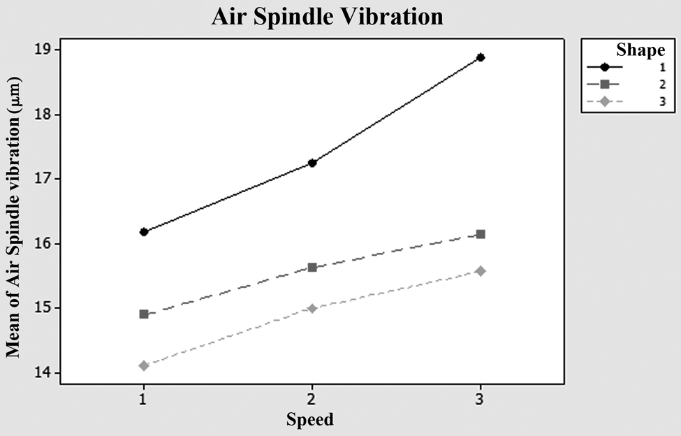
The plot showing the effect of interaction between air pocket shape and rotational speed on air spindle vibrations.
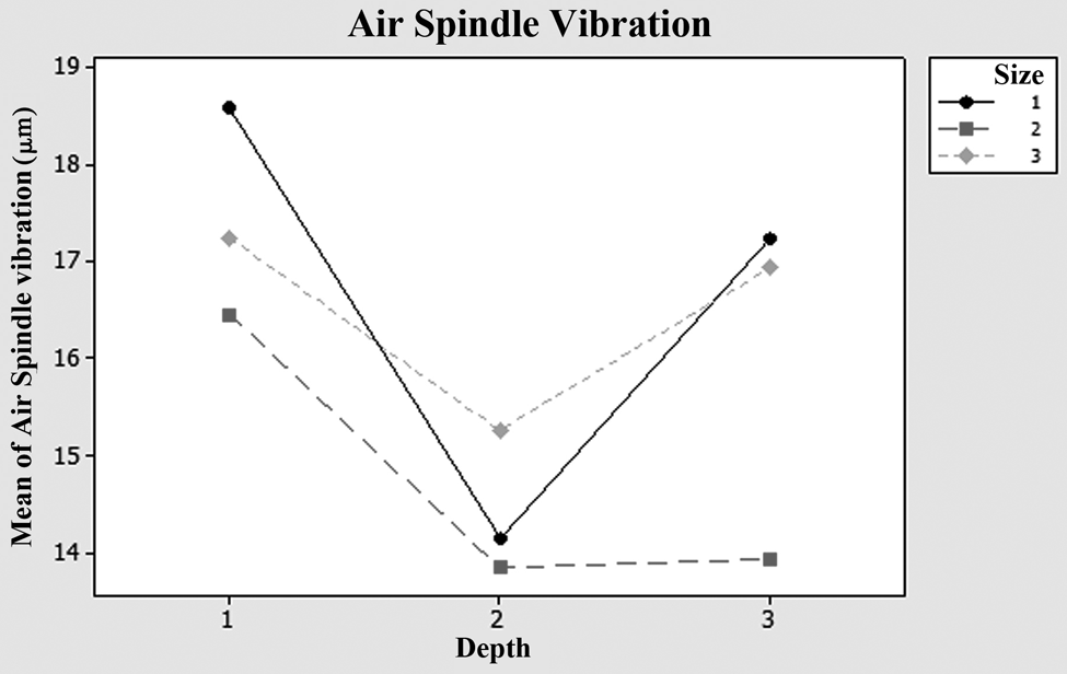
The plot showing the effect of interaction between air pocket size and depth on air spindle vibrations.
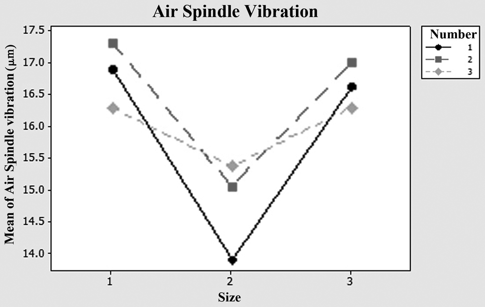
The plot showing the effect of interaction between air pocket size and number on air spindle vibrations.
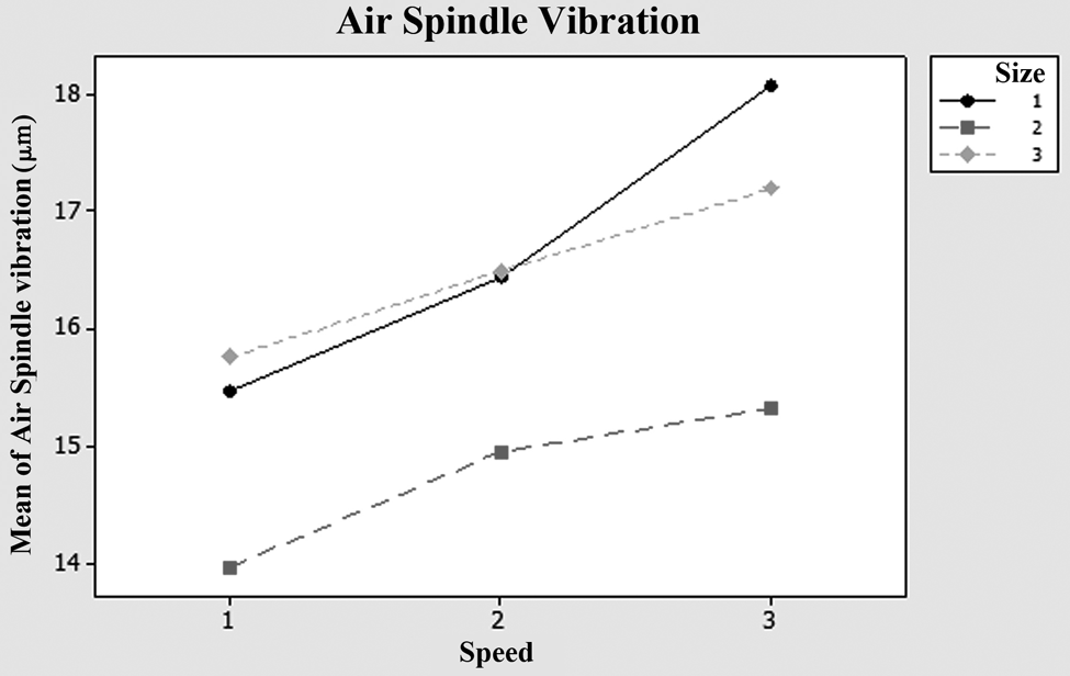
The plot showing the effect of interaction between air pocket size and rotational speed on air spindle vibrations.
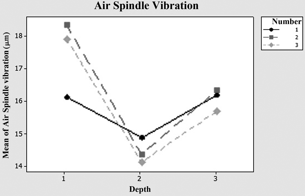
The plot showing the effect of interaction between air pocket depth and number on air spindle vibrations.
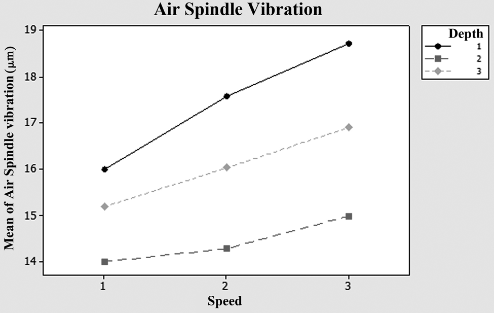
The plot showing the effect of interaction between air pocket depth and rotational speed on air spindle vibrations.
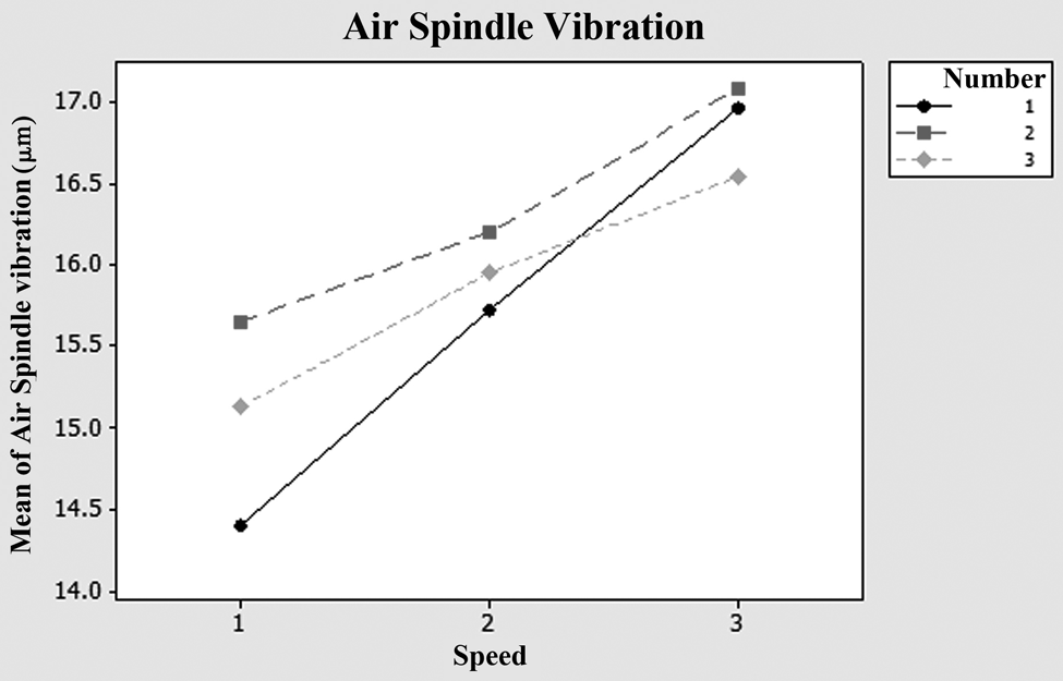
The plot showing the effect of interaction between air pocket number and rotational speed on air spindle vibrations.
According to Figure 12, air spindles with 200 mm2 area and rectangular pockets have minimum vibrations and those with 200 mm2 area and triangular pockets have maximum vibrations. From Figure 13, it is seen that rectangular air pockets with 3 mm depth and 1 mm depth have minimum and maximum vibrations, respectively. In Figure 14, minimum and maximum vibrations were observed in case of air spindles with two circular and two triangular pockets respectively. According to Figure 15, air spindles with circular pockets at 1800 r/min speed have minimum vibrations and those with triangular air pockets at 3600 r/min speed show maximum vibrations. From Figure 16, it has been observed that air pockets with 300 mm2 area and 3 mm depth have minimum vibrations and air pockets with 400 mm2 area and 1 mm depth have maximum vibrations. From Figure 17, it can be seen that air spindles with two 300 mm2 air pockets and those with two 400 mm2 air pockets have minimum and maximum vibrations, respectively. Figure 18 shows that air spindles with 300 mm2 air pockets at 1800 r/min speed have minimum vibrations and those with 400 mm2 air pockets at 3600 r/min speed have maximum vibrations. From Figure 19, it is seen that air spindles with four 3 mm depth air pockets show minimum vibrations and those with two 1 mm depth air pockets show maximum vibrations. Figure 20 shows that air spindles with 3 mm depth air pockets at 1800 r/min speed and those with 1 mm air pockets at 3600 r/min speed have minimum and maximum vibrations, respectively. Figure 21 shows that air spindles with two air pockets at 1800 r/min speed and those with two air pockets at 3600 r/min speed have minimum and maximum vibrations, respectively.
From these plots and results, it seems that rectangular and circular air pockets have lower vibrations due to their better pressure distribution in air gap. Air pockets of 300 mm2 size show lower vibration than both 200 and 400 mm2 air pockets. Also, from these experiment data, because of strike of air pressure on the rotor surface, air pockets with 1 mm depth have higher vibrations than other air pocket depths due to closeness of air inlet nozzle to rotor surface. An increase in the rotational speed of air spindle causes disturbance in air film, and thus increasing air spindle vibrations.
Conclusion
This study has investigated experimentally the effects of air pocket parameters including shape, size, depth, and number on air spindle vibrations in nanomachining. The triangular, rectangular, and circular geometries were selected as air pocket shape parameters, and 400, 300, and 200 mm2 areas as air pocket sizes. Air pocket depths for this study were selected as 1, 3, and 5 mm and number of air pockets considered as 2, 3, and 4 pockets. With three selected rotational speeds, totally 243 experiments were performed for studying air spindle vibrations. Conclusions from this study are follows:
Air spindle vibrations have direct effects on machined surface roughness; for this reason, in order to achieve very smooth surfaces, with nanometer resolutions, studying air spindle vibrations is very important;
Analysis using the DOE method showed that all estimated parameters play a significant role in vibration;
From the main effect plots for studied parameters, it was observed that the air spindle with two circular air pockets of 300 mm2 size and 3 mm depth at lowest rotational speed has minimum vibrations;
Overall, main effect plots and interaction effect plots show that air spindles with two circular/rectangular air pockets of 300 mm2 size and 3 mm depth at 1800 r/min speed have minimum vibrations;
At higher rotational speeds, the air spindles with four circular air pockets of 300 mm2 size and 3 mm depth have minimum vibrations;
Main effect plots for studied parameters show that air spindles with three triangular air pockets of 400 mm2 size and 1 mm depth at highest rotational speed have maximum vibrations.
Overall, from main effect plots and interaction effect plots, it is evident that air spindles with three triangular air pockets of 400 mm2 size and 1 mm depth at 3600 r/min speed have maximum vibrations.
Footnotes
Appendix 1
Declaration of conflicting interests
The authors declare that there is no conflict of interest.
Funding
This research received no specific grant from any funding agency in the public, commercial or not-for-profit sectors.