
Abstract
This study investigates the influence of silane-treated loofah vine stem microfiber and hybrid magneto-electric fillers (Fe2SO4 and biocarbon) on the electrical, magnetic, and electromagnetic interference (EMI) shielding properties of flexible PVA-based composites. The electrical conductivity increased significantly with hybrid filler loading, and among all specimens, PLF2 exhibited the most balanced and efficient conductive response, reaching 6.5 × 10⁻⁹ S/m, which is 6.5 × 10⁶% higher than neat PVA. This enhanced conductivity is attributed to the formation of semi-continuous conductive networks created by 1.5 vol.% Fe2SO4 and 1.5 vol.% biocarbon, supported by silane treatment that ensures uniform dispersion and low interfacial resistance. Magnetic measurements revealed progressive increases in both real (µ′) and imaginary (µ″) permeability with higher Fe2SO4 content, where PLF3 recorded the highest values—µ′: 3.24–4.20 and µ″: 0.64–1.49—due to the formation of dense magnetically responsive micro-domains that promote domain wall relaxation, dipole rotation, and interfacial polarization. EMI shielding performance followed a similar trend, with PLF3 achieving the maximum SE, ranging from 8.89 dB (E-band) to 30.06 dB (J-band), owing to the synergistic combination of conduction loss from biocarbon, magnetic loss from Fe2SO4, and multiple reflection pathways created by the fiber network. Overall, the hybrid reinforcement system demonstrates strong potential for flexible EMI shielding applications, with PLF2 being optimal for conductivity-driven designs and PLF3 excelling in magnetic and EMI attenuation mechanisms. This composite show potential for flexible EMI shielding, wearable electronics, sensors and energy storage applications.
Introduction
Advancements in electronic systems have progressed from preliminary circuits to compact, high-frequency and multifunctional architectures, and this rapid evolution has intensified issues associated with uncontrolled electromagnetic radiation. Although modern electronic devices enhance communication efficiency, monitoring capability, automation, and overall human convenience, their proliferation contributes to persistent electromagnetic pollution and escalating environmental strain due to material waste and energy dissipation. 1 Consequently, this interference disrupts signal fidelity, accelerates device malfunction, and fosters ecological imbalance, which necessitates the development of efficient electromagnetic interference (EMI) shielding materials. Therefore, polymer-based composites have gained prominence in shielding applications, owing to their lightweight nature, structural tunability, flexibility, corrosion resistance, and superior processing adaptability when compared with metals.
Furthermore, the integration of natural fibres into polymer matrices has gained widespread research traction, because these reinforcements provide biodegradability, low density, improved mechanical integrity, and reduced environmental impact. 2 Accordingly, the present investigation utilizes Loofah vine stem fibre, obtained from Luffa cylindrica, a botanical source containing approximately 60 to 68 % cellulose. Because this high cellulose content enhances matrix adhesion, structural uniformity, and reinforcement efficiency, it promotes better stress distribution and stability in functional composites. Additionally, using the fibre in refined microform increases surface activity, interphase compatibility, and flexibility, which is particularly beneficial for soft and bendable EMI shielding structures. Various scholars have noted the rising potential of natural fibre-reinforced polymer composites in electromagnetic shielding functionalities. For example, Gerald et al. 3 demonstrated the mechanical behaviour of Chromolaena odorata stem fiber reinforced composite and reported a tensile strength of 208 MPa and a Young’s modulus of 4 GPa. In a similar way, Kumar et al. 4 investigated the Licuala grandis leaf stalk fiber reinforced composite and determined a tensile strength of 354 MPa and a Young’s modulus of 6.6 GPa. Relatively, Admas et al. 5 examined the Ethiopian Typha latifolia fiber reinforced composite and recorded a tensile strength of 192.8 MPa.
However, despite the merits of natural fibre reinforcement, these composites alone often exhibit voids in the composite, thereby limiting their overall shielding capability. Thus, the application of functional fillers has become an advanced strategy for improving material performance. Moreover, this research utilized the hybrid filler concept, since the combination of two fillers enables synergistic absorption, improved dispersion, multi-mechanistic attenuation, and broader frequency range coverage. 6 In line with this, the present research incorporates Fe2SO4 and biocarbon derived from Parkia speciosa pods as a hybrid magneto-electric filler system. Furthermore, Fe2SO4 contributes magnetic permeability, spin-resonance absorption, and enhanced magnetic loss, it strengthens the magnetic attenuation pathways within the composite. Likewise, biocarbon offers conductive channels, interfacial polarization sites, and micro-porous electronic transport features, enabling stronger dielectric loss and improved electrical shielding. Therefore, the combination of magnetic (Fe2SO4) and conductive (biocarbon) fillers achieves a synergistic shielding response unattainable through single-phase fillers. Several researchers have examined the hybrid filler reinforced composite. For example, Shahabaz et al. 7 demonstrated the carbon fiber and hybrid Al2O3 and SiC particle reinforced epoxy composite and reported a tensile strength improvement of 29.54% and a modulus gain of 2.42%. Similarly, Alshammari et al. 8 examined the hybrid filler reinforced composite and observed increases of 127% in tensile strength, 86% in flexural strength, and 16.6% in impact strength. Likewise, Miniappan et al. 9 analysed the sisal fiber and hybrid filler reinforced composite and reported a flexural strength of 166.4 MPa and an impact strength of 5.34 J.m−2.
Nevertheless, both natural fibres and filler particulates inherently possess surface irregularities, polar groups, and moisture-associated deficiencies, which hinder effective interfacial bonding and reduce electromagnetic pathway continuity. Hence, silane surface modification is implemented for both the fibre and filler, as silane agents promote covalent linkages, decrease hydrophilicity, and strengthen fibre–matrix and filler–matrix compatibility. 10 Because silane treatment generates a chemically bonded, moisture-resistant interphase, it minimizes void formation, enhances mechanical cohesion, and supports magnetic interactions. Prior research has demonstrated that silane-treated reinforcements significantly elevate multi-functional composite behaviour. Typically, Brailson et al. 11 evaluated the surface modified Cocos nucifera L. var. typica fiber reinforced composite and reported a tensile strength of 128 MPa, a flexural strength of 119 MPa, and an impact strength of 9.9 J/cm2. Similarly, Senthamaraikannan et al. 12 assessed the alkali treated Mucuna atropurpurea fiber reinforced composite and determined a tensile strength ranging from 274.6 ± 29.5 to 307.3 ± 24.12 MPa and a tensile modulus ranging from 2.88 ± 1.026 to 4.633 ± 0.94 GPa. Correspondingly, Ahmed et al. 13 analysed the silane modified Al2O3 particle reinforced composite and concluded a thermal conductivity of 0.178 W/m·K and a tensile strength improvement of 66%.
This study investigates the synergistic effect of silane-treated Loofah vine stem microfibers combined with silane-modified Fe2SO4 and Parkia speciosa pod-derived biocarbon hybrid fillers on the electrical conductivity, magnetic permittivity, and electromagnetic interference shielding performance of flexible PVA composites. The research addresses a distinct gap, as the simultaneous integration of natural fiber, magnetic filler, conductive biocarbon, and dual surface functionalization has not been explored previously. The novelty of this work lies in its sustainable reinforcement strategy, hybrid magneto-electric design, and interface-engineered flexible shielding architecture. The resulting composites demonstrate significant potential for advanced applications, including flexible EMI shielding films, wearable electronic covers, portable device enclosures, lightweight circuit protection sheets, and adaptive electronic packaging solutions.
Experimental framework
Essential materials
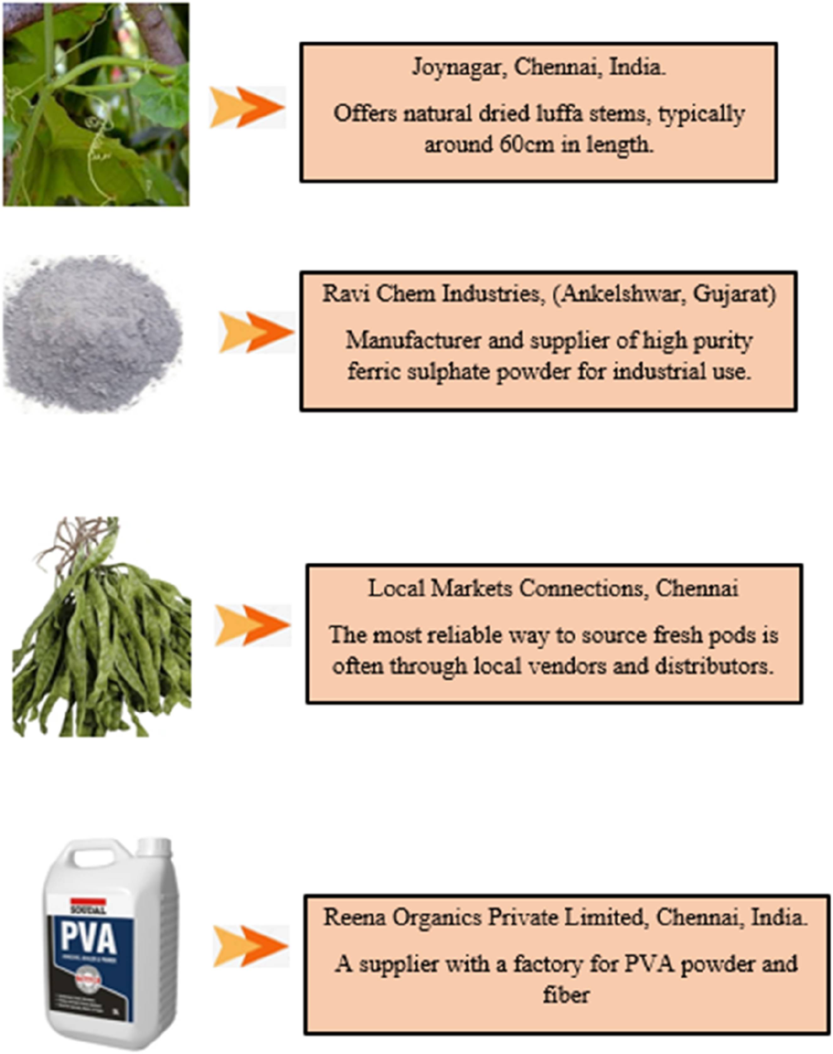
The following things explains the raw material used in this study with origin of purchasing and their details.
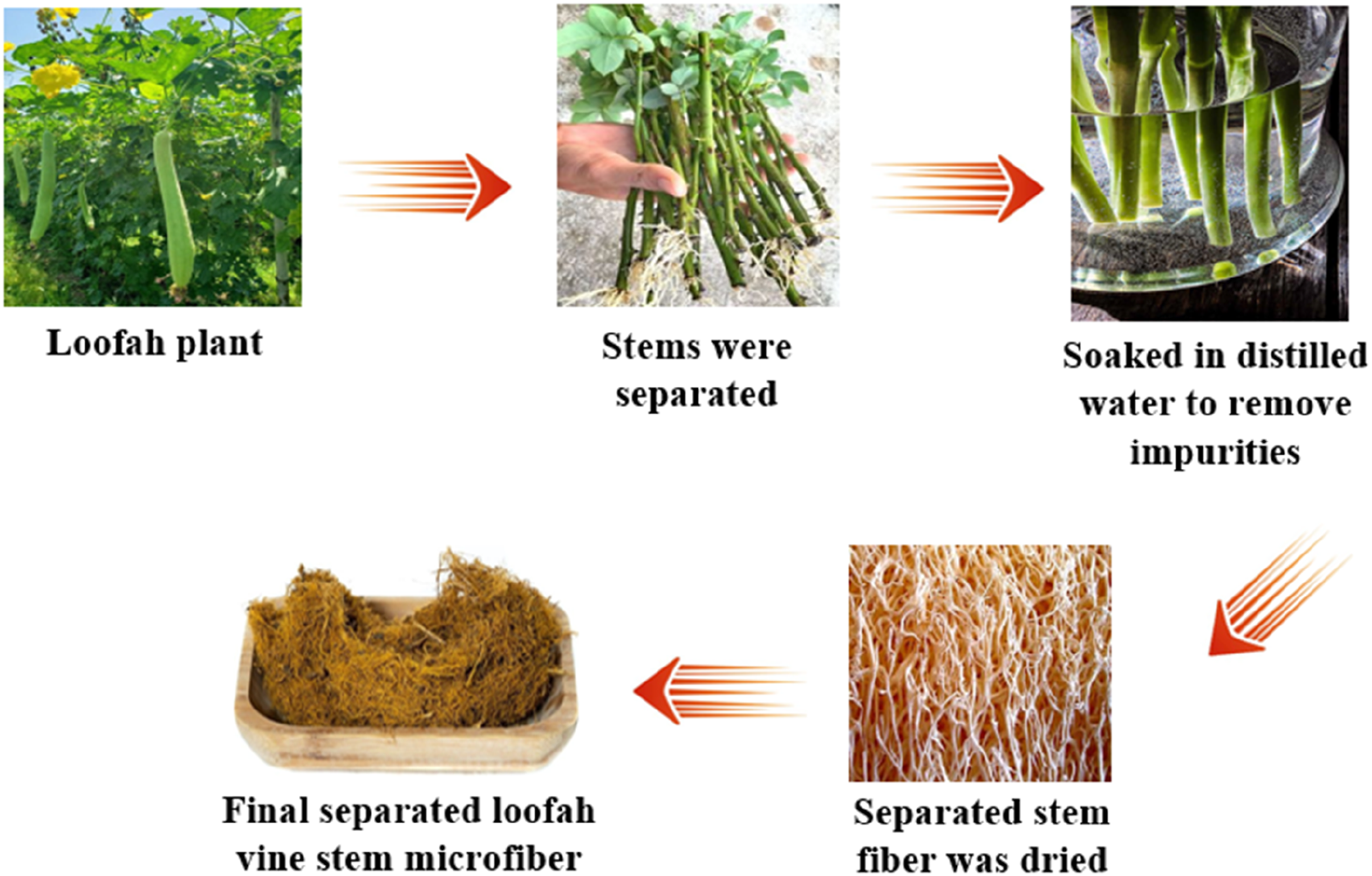
Microfiber separation process from loofah vine stems
The microfiber extraction process typically involves a combination of chemical treatments to break down a natural material into fine fibers.
14
A common chemical method was used such as washing and alkali treatment to remove impurities followed by a bleaching process to further purify the cellulose. Figure 1 displays disentangling microfibers from loofah stem networks. Removing micro fibrous fractions from loofah plant stems.
Biocarbon filler extraction process from Parkia Speciosa Pod
In this investigation, biocarbon filler particles can be extracted from Parkia Speciosa Pods. Before the process, collect the Parkia Speciosa Pods wash them thoroughly with deionized water to remove the dirt and debris. The cleansed pods were dried in hot air oven around 60°C for several days to remove moisture content and grind the dried pods into a fine powder using a centrifugal mill. Now, the powdered biomass was subjected to carbonization (a type of pyrolysis) in an inert atmosphere at high temperatures typically in range of 400°C to convert the organic material into a carbon rich char. This process, usually takes specific duration of 30 min.
15
To enhance the porosity and surface area of the biocarbon, the char was often chemically activated. The impregnated materials was then heated again at an elevated temperature at 600°C. After the activation process, the materials were repeatedly rinsed with distilled water, to remove residual activating agents until the filtrate reaches neutral pH. Simultaneously, washed biocarbon is then oven dried to remove any remaining moisture. Furthermore, resulting dry biocarbon was sieved using a sieve shaker to obtain particles within a specific size range which was suitable for use as a filler. Figure 2 portrays the biocarbon filler extraction process. Outline of biocarbon filler process.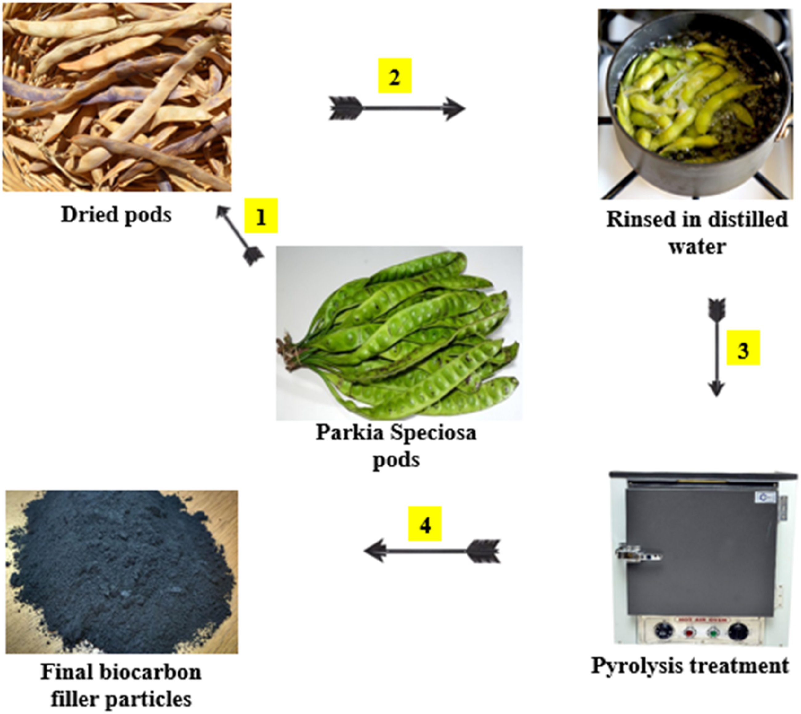
Figure 3 represents XRD pattern of the biocarbon filler particles exhibits a broad diffraction hump centered around 22°, which is characteristic of amorphous carbonaceous structures. The absence of sharp crystalline peaks confirms that the biocarbon primarily exists in a disordered phase, indicating incomplete graphitization during pyrolysis. This amorphous nature enhances surface reactivity and provides improved compatibility with polymer matrices. Overall, the XRD analysis validates the successful formation of amorphous biocarbon suitable for composite reinforcement. XRD proofing of biocarbon.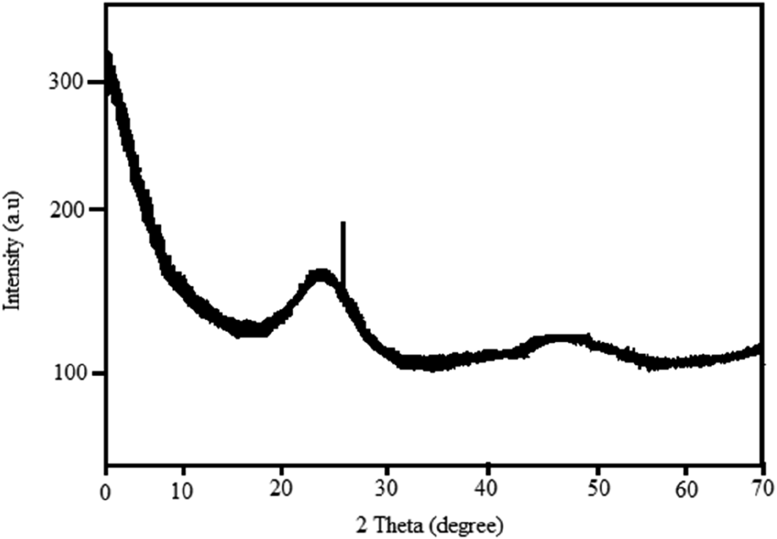
Silane treatment
Silane treatment was used to enhance the compatibility between microfibers/fillers and a polymer matrix by creating a strong chemical bond between the two surfaces. This process improves interfacial adhesion, which leads to better dispersion of the filler. First, the microfibers and filler particles are washed with distilled water and ethanol to remove surface impurities, followed by drying at 80°C for 3 h. The cleansed materials are immersed in a dilute NaOH solution for 45 min to activate surface hydroxyl groups. A silane coupling solution was prepared by mixing 3 vol. % of silane in a solvent mixture of ethanol and water.
16
The solution pH was adjusted to 5 using acetic acid to promote hydrolysis. The silane solution was stirred for 20 min to allow proper hydrolysis and formation of silanol groups. The microfibers and filler particles were immersed in the activated silane solution for 35 min with gentle stirring to ensure uniform coating on the surfaces. Further after the immersion, the treated microfibers/filler particles were removed and lightly rinsed with ethanol to remove unreacted silane molecules. The treated reinforcements are stored in desiccators to prevent moisture uptake before composite fabrication. Figure 4 silane treatment method. Surface treatment method.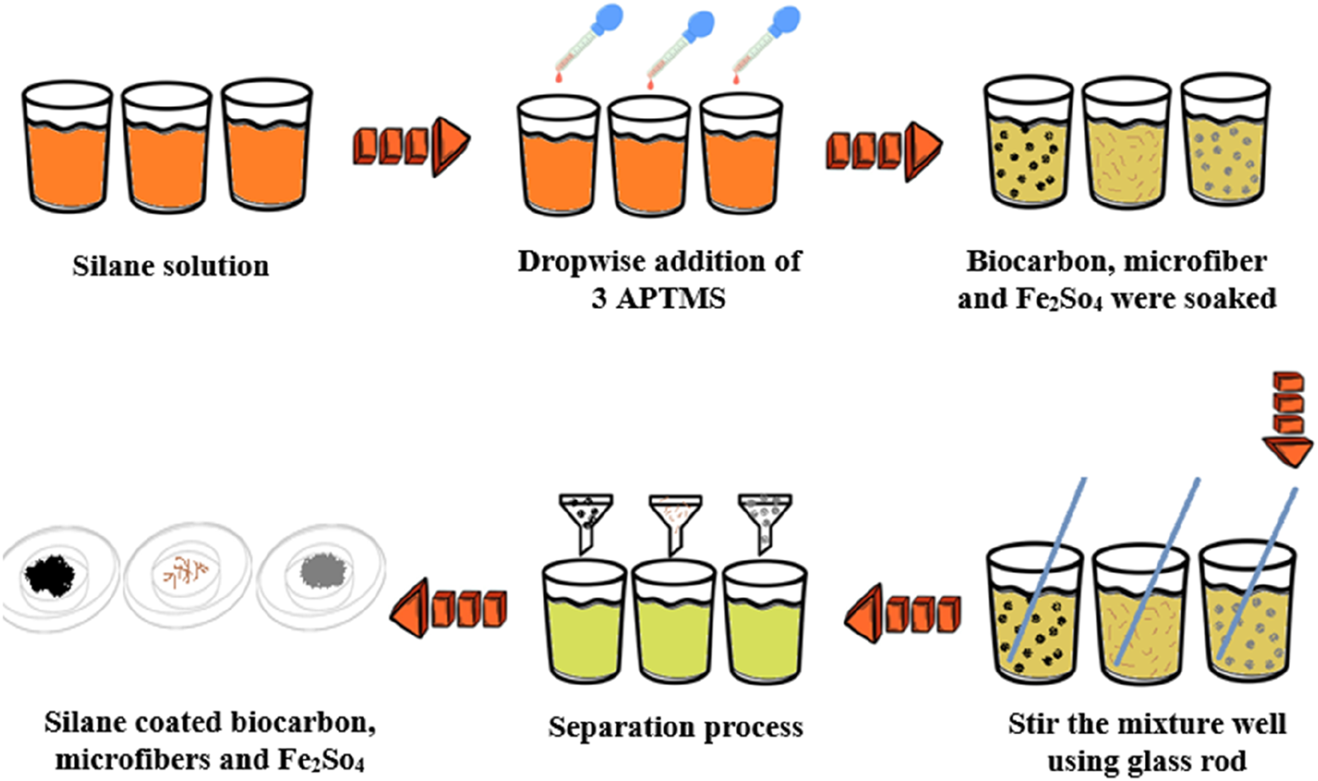
Development of composites
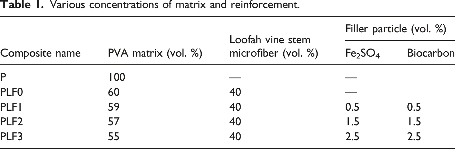
Various concentrations of matrix and reinforcement.
Characterization
After complete drying, the flexible composite film was carefully peeled from the substrate, conditioned at room temperature to stabilize its structure, and trimmed using a precision cutting tool to obtain specimens with accurate dimensions for further characterization. A set of electrical and electromagnetic characterization tests were conducted to determine their electrical conductivity, magnetic permittivity and electromagnetic shielding behaviour in the X band and Ku band frequency regions. Each test was carried out following the corresponding ASTM guidelines using calibrated equipment under controlled laboratory conditions. The complete testing parameters, instrument specifications and evaluation procedures are provided below.
Electrical conductivity
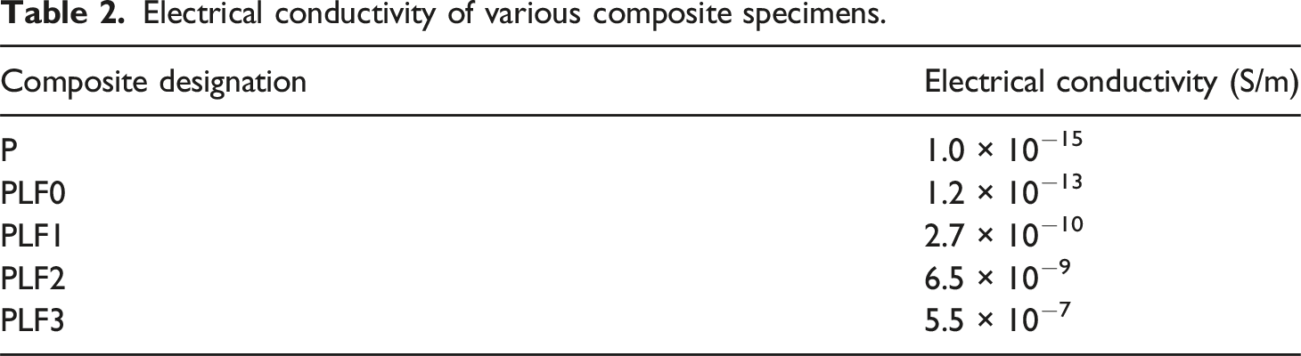
Electrical conductivity was measured according to ASTM D4496 using a Four-Point Probe System (Keithley 2400 SourceMeter Unit) with a constant current of 10 mA and 1 mm probe spacing. Rectangular specimens of 20 × 20 mm were used. The probe was placed on the specimen surface, and the voltage drop between the inner probes was recorded. Conductivity and resistivity were calculated using geometric correction factors. The results provided the charge transport ability of the composite.
Magnetic permittivity
Magnetic permittivity was determined using a Keysight 16454A Magnetic Fixture connected to an Agilent E4980A LCR Meter over 20 Hz to 2 MHz. Specimens of 20 × 20 mm was positioned between the fixture coils, and the impedance response under an alternating magnetic field was measured. The real and imaginary components of magnetic permittivity were extracted, indicating magnetic storage capacity and magnetic loss behaviour.
Electromagnetic interference shielding
EMI shielding effectiveness was evaluated as per ASTM D4935 using a Vector Network Analyzer (Keysight N5227B) with calibrated X band and Ku band waveguide fixtures. Circular specimens of 50 mm diameter were mounted in the waveguide holder, and S11 and S21 parameters were measured across 8.2 to 12.4 GHz and 12.4 to 18 GHz. Shielding effectiveness was calculated from reflected and transmitted power, revealing the composite’s attenuation capability in both frequency bands.
Results and discussion
Mechanical behavior
The tensile, tear and elongation properties of the PVA-loofah vine stem microfiber composites clearly demonstrate the influence of fiber reinforcement and hybrid filler addition on load bearing capacity and ductility as illustrated in Figure 5. The neat PVA matrix (P) exhibits the lowest tensile strength of 32 ± 1.5 MPa and tear strength of 18 ± 1.0 N/mm accompanied by a high elongation at break of 210 ± 8%, reflecting the ductile nature of the unreinforced polymer where deformation was governed by polymer chain mobility rather than effective stress transfer. With the incorporation of 40 vol. % loofah microfiber (PLF0), tensile and tear strengths increase significantly to 48 ± 2.0 MPa and 32 ± 1.4 N/mm while elongation decreases to 120 ± 6%. This improvement was attributed to the load bearing role of the microfibers which restrict matrix deformation and promote stress transfer across the fiber matrix interface leading to enhanced resistance against tensile and tearing loads.
18
Mechanical performance (a) Tensile, (b) Tear and (c) Elongation at break of the samples.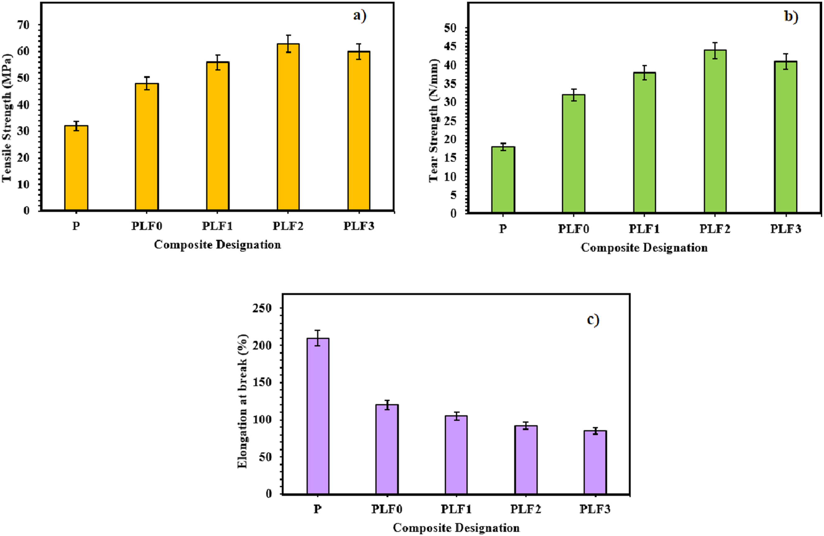
The addition of hybrid fillers in PLF1 further enhances mechanical performance with tensile strength rising to 56 ± 2.3 MPa and tear strength to 38 ± 1.6 N/mm while elongation decreases to 105 ± 5%. The presence of Fe2SO4 and biocarbon fillers contributes to improved interfacial adhesion and localized stress redistribution thereby increasing resistance to crack initiation and propagation under tensile and tear loading. At moderate filler loading, PLF2 exhibits the highest tensile and tear strengths of 63 ± 2.6 MPa and 44 ± 1.8 N/mm with elongation at break reduced to 92 ± 4%. This indicates an optimal balance between reinforcement efficiency and matrix continuity where effective fiber filler matrix interactions maximize stress transfer and crack resistance without severe embrittlement. In PLF3, a slight reduction in tensile strength to 60 ± 2.5 MPa and tear strength to 41 ± 1.7 N/mm was observed accompanied by further reduced elongation of 85 ± 4%. This trend suggests the onset of filler agglomeration and increased matrix stiffness which limits chain mobility and leads to earlier fracture despite improved resistance to tearing compared to lower filler contents. 19 Overall, the results confirm that fiber reinforcement significantly enhances strength while hybrid fillers further improve tensile and tear resistance at the expense of ductility with PLF2 representing the optimum composition for balanced mechanical performance.
The SEM micrographs of the tensile fractured surfaces provide clear insight into the structure property relationships of the composites. The neat PVA matrix (Figure 6(a)) shows a relatively smooth and featureless fracture surface with signs of extensive plastic deformation indicating ductile failure governed by matrix tearing and unrestricted crack propagation. With the incorporation of silane treated microfiber (Figure 6(b)), the fracture surface becomes noticeably rougher with well-embedded fibers, limited fiber pull out and evidence of crack deflection and fiber bridging confirming effective interfacial adhesion and improved stress transfer from the matrix to the reinforcement. At the optimum hybrid filler loading (Figure 6(c)), the fracture morphology is highly tortuous characterized by uniform dispersion of fibers and fillers, minimal voids and strong interfacial bonding which promotes microcrack pinning and crack blunting and thereby enhances resistance to crack initiation and growth. In contrast, at higher filler content (Figure 6(d)), localized filler agglomeration and micro-voids are observed near the fiber matrix interface leading to stress concentration sites and premature micro-crack formation. This morphological change explains the slight deterioration in mechanical performance at higher filler loading while still maintaining a reinforced fracture network compared to the neat matrix. SEM micrographs of (a) P, (b) PLF0, (c) PLF2 and (d) PLF3.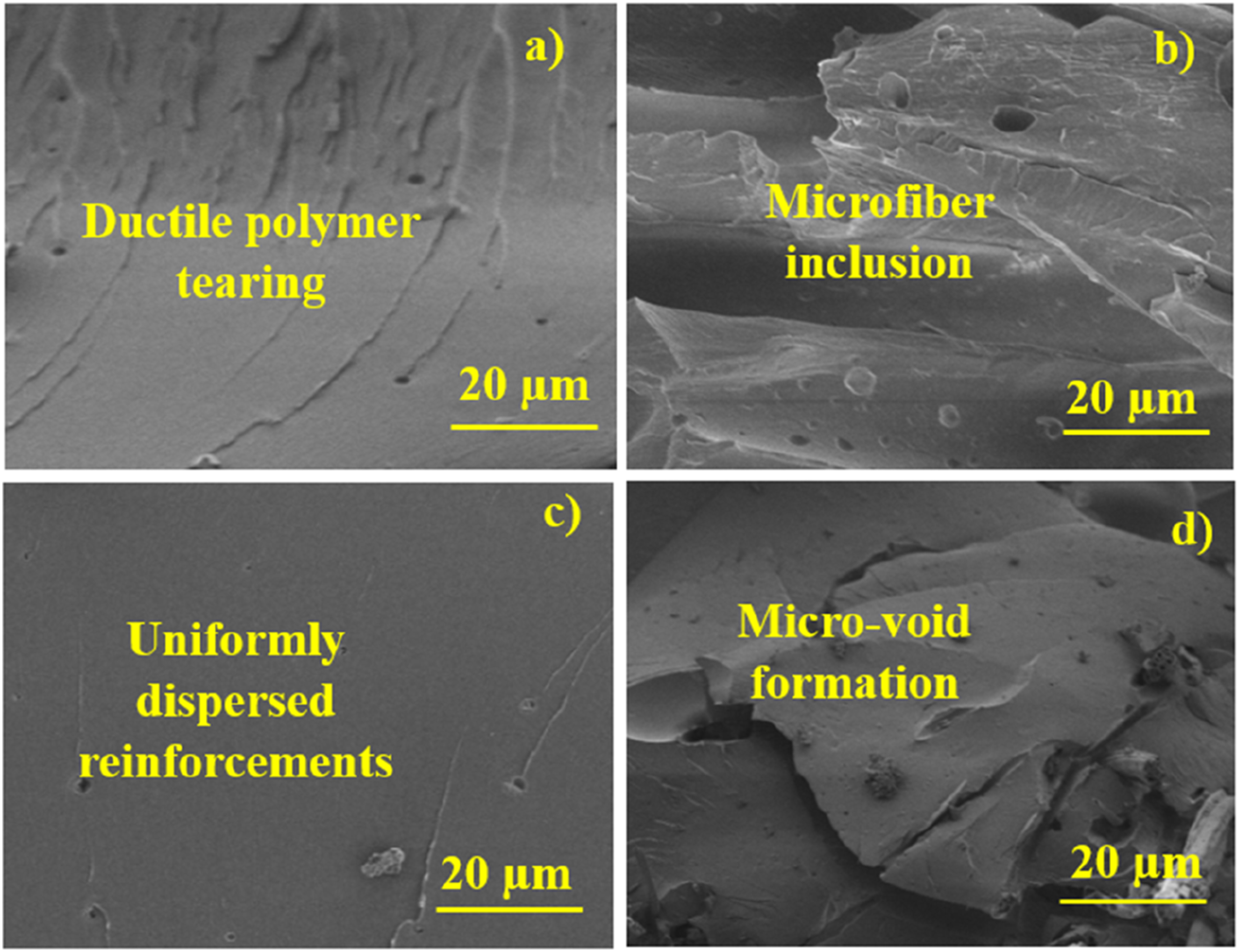
Electrical conductivity
Electrical conductivity of various composite specimens.
Magnetic properties
The magnetic permeability of the hybrid magneto-electric composites increased systematically with rising concentrations of silane-treated Fe2SO4 and biocarbon, demonstrating the effectiveness of the filler system in enhancing both magnetic storage (real part, µ′) and magnetic loss (imaginary part, µ″) across the measured frequency range. In the real part (µ′), PLF1 showed values ranging from 2.25 at 8 Hz to 3.18 at 20 Hz, reflecting the initial contribution of 0.5 vol.% Fe2SO4, whose paramagnetic nature enhances magnetic dipole alignment under an alternating field. Silane treatment plays a crucial role here by improving particle dispersion and establishing stronger interfacial bonding with PVA, preventing particle clustering and ensuring that the applied magnetic field efficiently interacts with individual Fe2SO4 particles. In PLF2, µ′ increased further to 2.72–3.73, resulting from the higher loading of 1.5 vol.% Fe2SO4, which increases the density of magnetically active sites, leading to stronger dipole interactions and improved magnetic domain response to the external field. The presence of biocarbon at the same loading also supports magnetic behaviour indirectly by promoting localized conductive networks, which enhance electromagnetic coupling within the matrix. PLF3 exhibited the highest µ′ values, ranging from 3.24 at 8 Hz to 4.20 at 20 Hz, due to the increased Fe2SO4 concentration (2.5 vol.%) forming more continuous magnetic micro-domains. These well-distributed, silane-treated particles amplify magnetization under the AC field and minimize interparticle spacing, leading to more effective polarization relaxation and magnetic energy storage. 23
For the imaginary part (µ″), which represents magnetic loss mechanisms, a similar ascending trend was observed. PLF1 recorded values from 0.43 to 1.18, indicating moderate magnetic losses attributed to natural resonance, domain wall motion, and interfacial polarization caused by the low filler content. At this stage, losses occur primarily due to isolated Fe2SO4 particles undergoing delayed response to the alternating magnetic field. In PLF2, µ″ increased to 0.54–1.28, corresponding to stronger magnetic damping effects resulting from higher Fe2SO4 loading. The increased particle density promotes enhanced domain wall friction, eddy current formation, and Maxwell–Wagner interfacial relaxation, all of which contribute to higher magnetic energy dissipation. The presence of biocarbon increases the composite’s conductivity slightly, assisting the development of localized eddy currents that add to magnetic losses. 24 Finally, PLF3 displayed the highest µ″ values (0.64–1.49), signifying the most efficient magnetic loss behaviour. At this filler loading, the Fe2SO4 particles form near-continuous magnetically responsive paths, ensuring that dipole rotation, domain wall movement, and interfacial polarization occur more strongly and more frequently. 25 The silane treatment ensures uniform dispersion and prevents agglomeration, maximizing the effective surface area for field interaction and allowing the composite to dissipate magnetic energy more effectively.
Overall, both µ′ and µ″ increased with frequency and filler concentration, demonstrating that the hybrid magneto-electric system effectively enhances magnetic storage and magnetic loss behaviour. These improvements are essential for EMI shielding applications, where strong magnetic response and high magnetic losses contribute significantly to absorption-dominated shielding performance. Figure 7 shows Magnetic properties of various composite specimens. Magnetic properties of various composite specimens.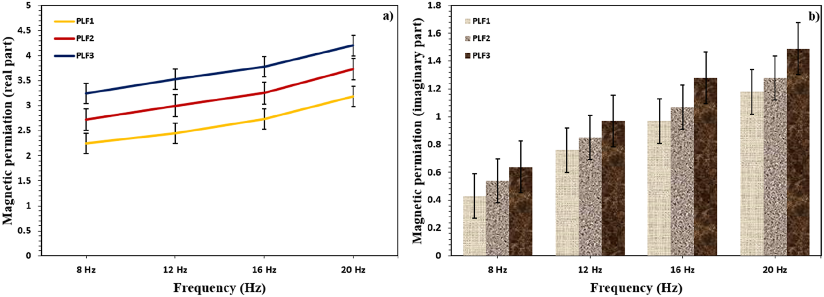
EMI properties
The EMI shielding effectiveness (SE) of the composites consistently improved with the incorporation of silane-treated loofah vine stem microfiber and the progressive increase in hybrid magneto-electric fillers, confirming the dominant role of combined dielectric and magnetic loss mechanisms in electromagnetic (EM) attenuation. When the total shielding effectiveness (SET) is resolved into reflection (SER) and absorption (SEA) components, it is evident that shielding in all composites is predominantly absorption-controlled. The neat PVA matrix (P) exhibited very low SET values of 2.23 dB (E), 8.89 dB (F), 13.33 dB (I), and 20.01 dB (J), arising from small contributions of SER (0.72–5.10 dB) and SEA (1.51–14.91 dB). This behavior is attributed to the extremely low electrical conductivity and lack of magnetic response of PVA, resulting in negligible reflection at the air–material interface and limited absorption of incident EM waves. 26
In PLF0, the incorporation of 40 vol.% silane-treated microfiber increased SET to 3.39–24.45 dB. This improvement originates mainly from enhanced absorption (SEA = 2.38–17.53 dB), with a modest increase in reflection (SER = 1.01–6.92 dB). The interconnected fibrous network promotes multiple internal reflections and dipole polarization at the fiber–matrix interface, thereby increasing absorption-based shielding. The introduction of 0.5 vol% silane-treated Fe2SO4 and 0.5 vol% silane-treated biocarbon in PLF1 further increased SET to 4.45 dB (E), 11.12 dB (F), 17.78 dB (I), and 25.61 dB (J). This enhancement is mainly driven by a rise in SEA (3.16–17.73 dB), while SER increases moderately (1.29–7.88 dB). Biocarbon contributes to dielectric loss through improved charge transport and interfacial polarization, 27 whereas Fe2SO4 introduces magnetic dipole relaxation and natural resonance, enabling more efficient absorption of EM radiation. 28
For PLF2, higher hybrid filler loading (1.5 vol.% Fe2SO4 + 1.5 vol.% biocarbon) increased SET to 5.62–27.84 dB, with SEA (3.96–18.72 dB) clearly exceeding SER (1.66–9.12 dB). At this stage, synergistic loss mechanisms—dipole polarization, interfacial Maxwell–Wagner relaxation, magnetic hysteresis, and eddy current losses—operate simultaneously, resulting in substantially enhanced absorption-dominated shielding. 29 PLF3 exhibited the highest EMI shielding performance, with SET values of 8.89 dB (E), 14.39 dB (F), 20.32 dB (I), and 30.06 dB (J). These values arise from the combined increase in SEA (6.44–19.65 dB) and SER (2.45–10.41 dB), with absorption remaining the dominant contributor. At this maximum hybrid filler loading (2.5 vol.% Fe2SO4 + 2.5 vol.% biocarbon), biocarbon forms near-continuous conductive pathways that enhance conduction loss, while Fe2SO4 ensures strong magnetic dipole relaxation and resonance, particularly at higher frequencies. Silane treatment plays a crucial role by improving filler dispersion, suppressing agglomeration, and maximizing interfacial polarization.
Overall, decomposition of SET into SER and SEA confirms that EMI shielding in these composites is governed primarily by absorption rather than reflection. The progressive increase in SEA with hybrid filler loading demonstrates the synergistic contribution of dielectric and magnetic losses to EM wave attenuation. The combined effect of reinforced fiber architecture and hybrid magneto-electric fillers enables PLF3 to achieve the most effective shielding across all measured frequencies. Figure 8 shows the EMI SE of the various composite specimens. a) Absorption, (b) Reflection and (c) Total EMI shielding of various composite specimens.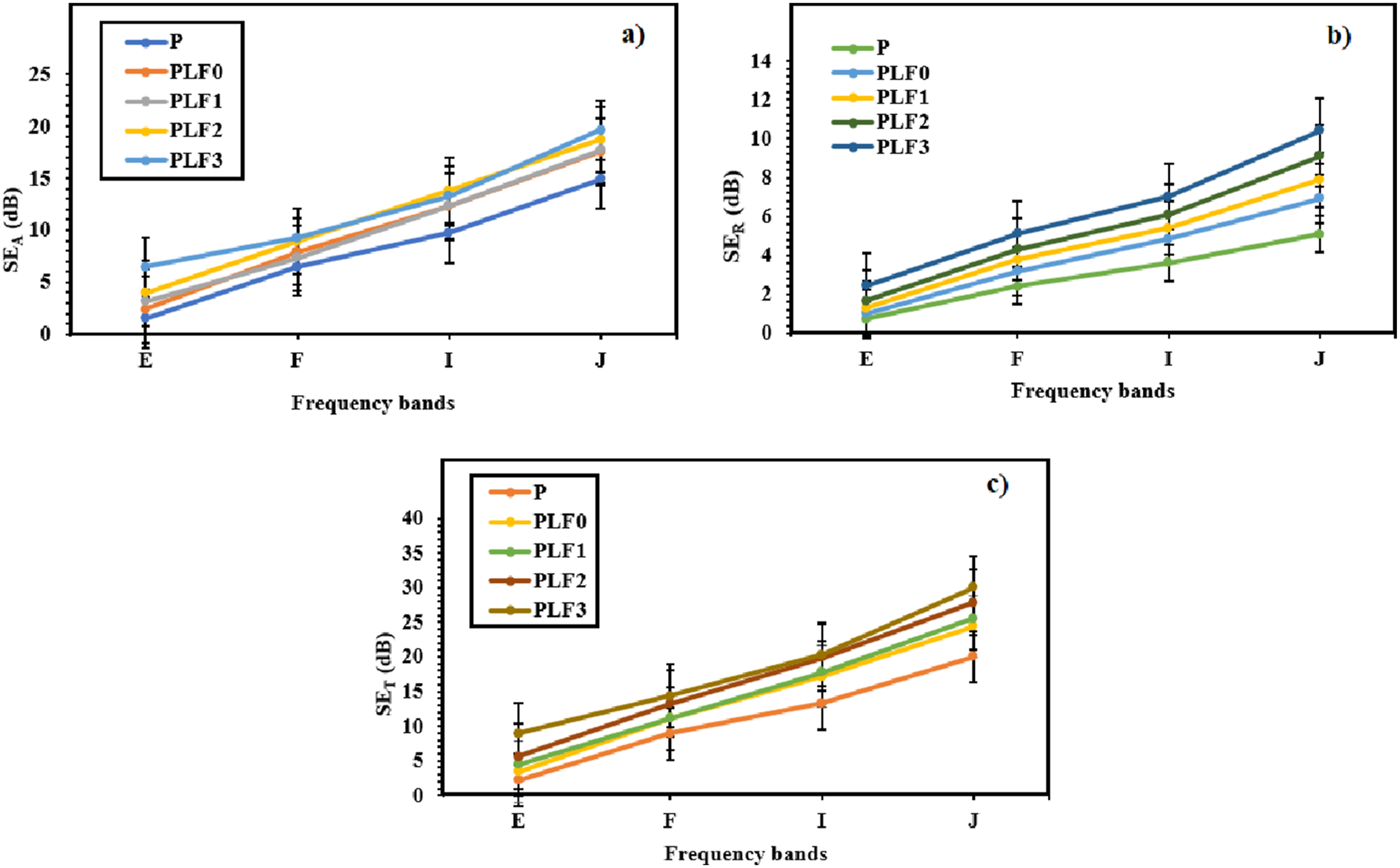
Conclusions
In conclusion, the incorporation of silane-treated microfiber along with hybrid Fe2SO4–biocarbon fillers effectively enhanced the multifunctional performance of PVA composites. Electrical conductivity increased by several orders of magnitude with filler loading, and PLF2 emerged as the most efficient specimen, reaching 6.5 × 10⁻⁹ S/m due to the development of semi-continuous conductive pathways supported by uniform filler dispersion and improved interfacial adhesion. Magnetic properties improved steadily with increasing Fe2SO4 content, with PLF3 delivering the highest magnetic permeability values (µ′: 3.24–4.20; µ″: 0.64–1.49), indicating strong magnetic dipole relaxation, natural resonance, and enhanced magnetic energy dissipation. This superior magnetic responsiveness directly translated to EMI shielding performance, where PLF3 showed the highest SE, ranging from 8.89 dB to 30.06 dB, driven by combined dielectric loss, magnetic loss, and conduction loss mechanisms. In summary, PLF2 is best suited for conductivity-dependent applications, whereas PLF3 provides the strongest overall performance for magnetic and electromagnetic shielding, confirming the efficacy of the hybrid magneto-electric reinforcement strategy in flexible composite systems.
Future scope
Further research may focus on optimizing filler ratios and dispersion techniques to enhance both mechanical flexibility and EMI shielding simultaneously, exploring long-term environmental stability for wearable and flexible electronics, and integrating these composites into scalable devices for energy storage, sensors, and smart electromagnetic shielding applications.
Footnotes
Author contributions
M. Sreenivasa Reddy – Research, writing and testing.
R. Sunder– Material arrangement and writing.
Dafik D. – Testing support.
Ika Hesti Agustin – Drafting.
Declaration of conflicting interests
The authors declared no potential conflicts of interest with respect to the research, authorship, and/or publication of this article.
Funding
The authors received no financial support for the research, authorship, and/or publication of this article.
Data Availability Statement
The required data can be given based on request.