
Abstract
Fiber-reinforced composite materials are replacing metallic components due to their higher specific strength and stiffness. Automation and thermoplastics emerged to overcome the time and labor intensive manual techniques and the long curing cycles associated with processing thermoset-based composites. Thermoplastics are processed through fusion bonding which involves applying heat and pressure at the interface. Together with automated techniques (such as automated fiber placement, and automated tape laying), a fast, clean, out-of-autoclave, and automated process can be obtained. A detailed review of thermoplastic composites processing through automated methods is presented. It sheds the light on the materials used and the different heat sources incorporated with the pros and cons of each, with concentration mainly on hot gas torch, laser, and ultrasonic heating. A thorough illustration of the several mechanisms involved in a tow/tape placement process is tackled such as heat transfer, intimate contact development, molecular interdiffusion, void consolidation and growth, thermal degradation, crystallization, and so on. Few gaps and recommendations are included related to materials, laser heat source, heat transfer model, and the use of silicone rubber rollers. A review of optimization studies for tape placement processes is summarized including the main controllable variables and product quality parameters (or responses), with some of the major findings for laser and hot gas torch systems being presented. Both mechanical and physical characterizations are also reviewed including several testing techniques such as short beam shear, double cantilever beam, lap shear, wedge peel, differential scanning calorimetry, and so on. Challenges, however, still exist, such as achieving the autoclave-level mechanical properties and complying with the porosity levels required by the aerospace industry. More work is still necessary to overcome these challenges as well as increase the throughput of the process before it can be totally commercialized.
Keywords
Introduction
Since the early 1960s, composite materials have been used increasingly as high-performance materials for structural applications. During this period, the technology was evolved mainly within the aerospace industry. Later on, with the development of manufacturing and processing techniques, the technology expanded to other industries such as automotive, mass transit, biomedical, marine, electronics, and civil infrastructure. 1 –3 Fiber-reinforced composite materials are potentially used as a replacement to metallic components due to the considerable weight reductions they offer combined with their high strength and stiffness. Other advantages include increasing mechanical properties, creating complex shapes, reducing the number of components in a part, reducing cost, and obtaining properties tailored to applications thanks to their high anisotropy. 4 –9
Traditionally, low production volumes of composite structures have been limited for two main reasons: (1) hand (manual) layup process which is time and labor intensive and (2) long post-processing time (autoclave curing cycles) associated with the use of the common thermoset polymers. The first is overcome by the development of automated placement techniques 10 in which repeatability is not an issue anymore, 11 whereas the other is taken care by introducing thermoplastic composites as an alternative to thermosets. Thermoplastic composites are usually processed through fusion bonding which involves the application of heat and pressure at the interface 8 ; hence, they have the potential of being rapidly processed in situ without the need of curing in autoclaves. 10,12,13 Interest in development of thermoplastic composites is also driven by their increased damage tolerance, high impact resistance, chemical and solvent resistance, infinite shelf life and low storage costs, weldability, and recyclability. 4,9,12,14,15 Furthermore, combining fusion bonding with an automated placement process allows the composite part to be bonded in situ as it is placed with a resulting process that is fast, clean, out-of-autoclave (OOA), and automated. 10,12,16 –19 However, since thermoplastics are stiff and highly viscous, a main disadvantage is the requirement of high processing pressure and temperature which makes them very costly to manufacture. 8,20,21 Furthermore, since heating and cooling rates are so fast, and pressure is applied for a very short time and is lower than that in an autoclave, it is challenging to obtain the autoclave-level mechanical properties. 10,22,23
Automated techniques, such as automated fiber placement (AFP) and automated tape laying (ATL), are among the promising processes to provide in situ consolidation of thermoplastic composites with high throughputs 24,25 and are used today to produce advanced composite laminates from unidirectional pre-impregnated (prepreg) tows or tapes. ATL usually uses wider tapes of up to 304.8 mm (12 in), whereas AFP utilizes narrower tapes usually between 6.35 mm (0.25 in) and 25.4 mm (1 in). In this sense, ATL is a faster technique, however, to increase their material deposition rates; AFP machines are usually incorporated with heads that can handle multiple tows at the same time. 26 –29 The automated tow or tape placement (ATP) is very common in the literature to refer to these processes, although AFP can still be found in some other works. ATP machines are capable of producing different shapes such as simple flat laminates, panels with mild curvatures, and three-dimensional (3-D) surfaces 30,31 with actual examples including aircraft wing skins, frames, stringers, and wing boxes, fuselage structures, and deep submersibles. 2,25,32 –35
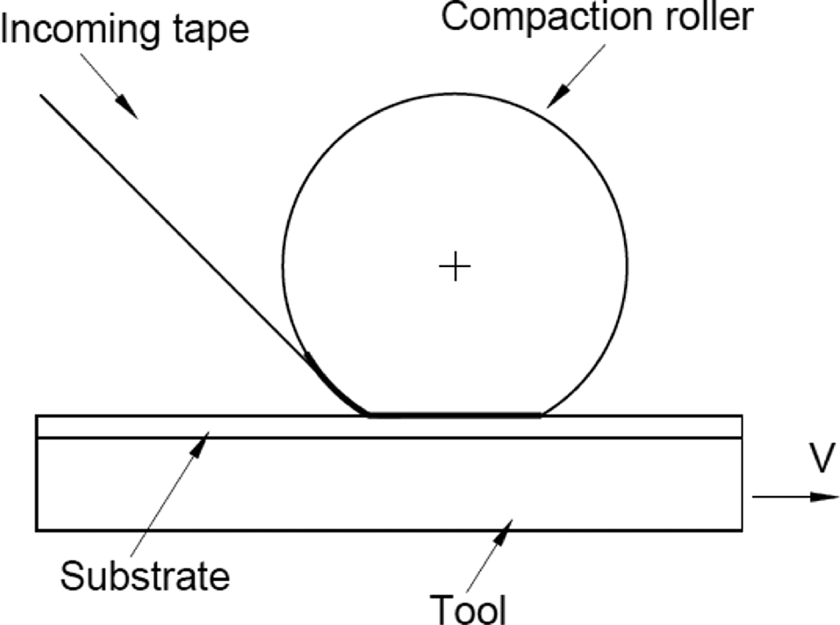
A typical in situ thermoplastic ATP process is shown in Figure 1. A unidirectional prepreg tape is fed down to the top surface of the previously placed layers (substrate). The surfaces of the tape and the substrate are then heated using a heat source as they approach the nip point (the location where the incoming tape comes in contact with the substrate). The melted surfaces are then pressed against each other by the compaction device (usually a roller), resulting in a bond. 10 A closely related process, derived from filament winding, is the tape winding process, which has a low-cost setup without a robotic or gantry-mounted head, and involves a mandrel/tool having a cylindrical shape so that circular rings can be processed. Both flat laminates 9,10,13,16,17,19,21,22,25,30,31,33,35 –69 and circular rings 20,55,70,71 –84 were investigated as well as elliptical rings. 76 Although a promising technique, ATP process still has many challenges to be overcome before it can be fully commercialized. Besides the requirement of achieving autoclave-level mechanical properties at the deposition rates demanded by industry 23,25,85 mentioned earlier, the process also has to achieve the desired degree of crystallinity when using semi-crystalline thermoplastics, 18 eliminate or reduce induced residual stresses which may lead to delaminations, 18,85 and sort out the issue of higher porosity levels above the 1% threshold required by the aerospace industry. 27,34
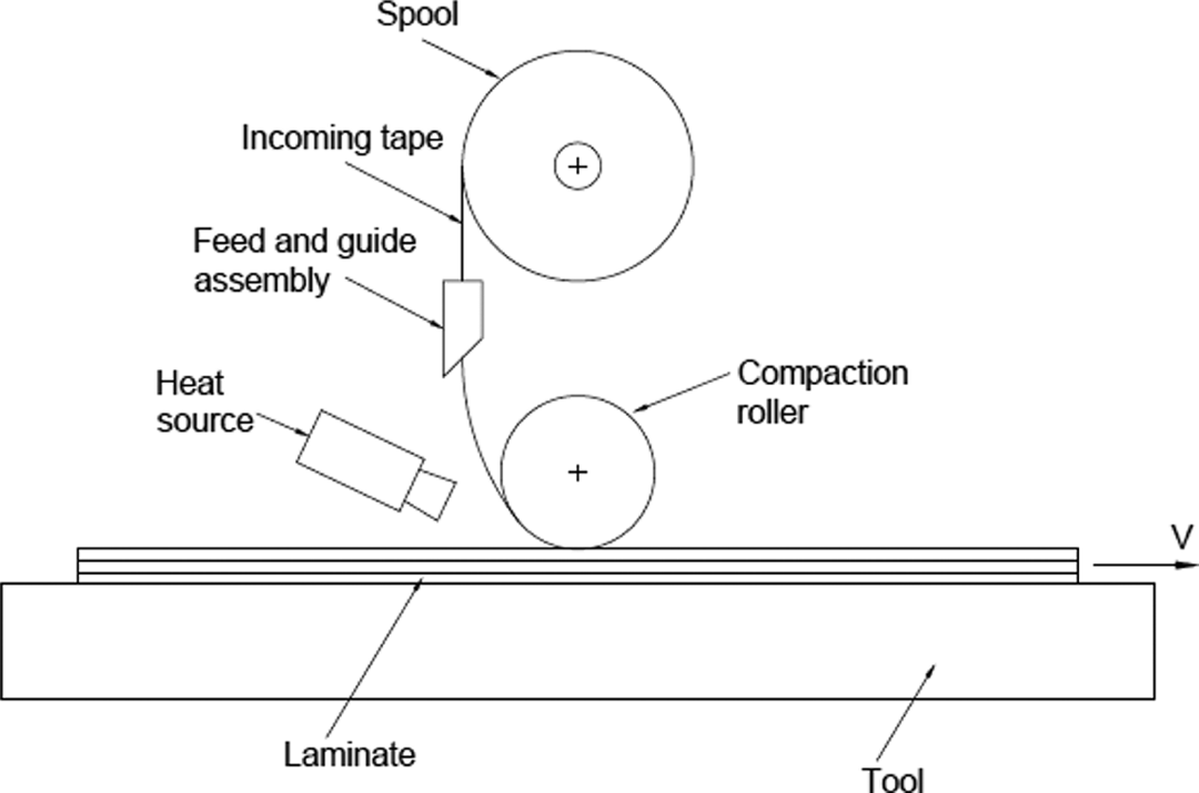
Typical ATP process.
Material system
Carbon fiber (CF) is the preferred reinforcement in composites in most advanced applications due to its high strength, lightweight, superior stiffness, electrical conductivity, low thermal expansion, high thermal conductivity, and corrosion resistance. The three most common used fibers are AS4, IM6, and IM7. AS4 has a higher strain, whereas IM6 and IM7 have higher tensile strength and modulus and good shear strength. 86
The high-performance thermoplastic resins are characterized by their high glass transition temperatures (T g) which allow them to have good mechanical performance at temperatures much higher than the conventional thermoplastics and, in some cases, than the polyester and epoxy thermosets. 87 A detailed review of principal thermoplastic matrix systems, their properties, as well as processing methods is available in the study by Chang and Lees. 88 Poly-ether-ether-ketone (PEEK) is by far the most commonly used thermoplastic in tape placement processes. It can be continuously used at 250°C. 89 PEEK has many advantages such as large database, very high toughness and damage tolerance, excellent environmental resistance, good resistance to creep and fatigue, and very good wear resistance. 90
Hence, the combination of CF and PEEK matrix, CF/PEEK, is widely used for high temperature applications in the aerospace industry. 30 The aromatic polymer composite (APC-2) is the very common trade name used by Cytec for CF/PEEK tapes. APC-2/AS4 was used extensively, 18,24,27,30,35,44 –47,56,60 –67,70,75,77 –79,82,83,85,91 –123 whereas other APC-2 versions were less investigated, such as APC-2/IM6 124,125 and APC-2/lM7. 72,73 Many of these tapes/tows had a narrow width of 6.35 mm (0.25 in). 20,27,33,64,66,70,77 –79,94,98,108 Recently, CF/PEEK tapes produced by Suprem are also common, such as AS4/PEEK 9,10,13,16,17,39 –41,126 and IM7/PEEK. 22,23,42,127,128 Furthermore, AS4/PEEK tapes produced by TenCate Advanced Composites were also used. 20,55,70,101 There are different other materials being used and investigated in the literature, such as CF/polyphenylene sulphide (PPS), 50 –52,75,83,84,100,129,130 CF/polyamide (PA), 48,131,132 CF/poly-ether-imide (PEI), 15,54,133 –136 CF/poly-ether-PEKK, 58,75,130,137 –141 glass fiber (GF)/polypropylene (PP), 21,26,80,142 –145 GF/PA66, 126 and GF/PPS. 83,144 It is obvious that the vast majority of the work on ATP involves CF/PEEK prepregs. Many of the modeling works were validated by repeating studies by different researchers and/or by performing experiments involving this specific material. However, to commercialize the ATP process, it has to be capable of being used with a wide variety of materials and still produce the minimum desired quality by the respective industries. In order to achieve this, more work is thought to be necessary which involves the use of a multitude of different other materials.
Heat sources
Thermoplastics are processed by fusion bonding in which two composite plies or parts can be bonded by melting their surfaces while applying pressure. 84 There are several heating methods to achieve this type of bonding including static or discontinuous methods (e.g. resistance welding) in which plies are first stacked and then consolidated, as well as dynamic or continuous methods (e.g. hot gas, infrared (IR), or laser heating) in which consolidation takes place while the tape and/or laminate are in motion. 83,84 In ATP techniques, the heat source plays an important role in the efficiency of the process, the final quality of the parts, and the processing costs. A wide range of different heat sources were evaluated: (i) laser heating devices (carbon dioxide (CO2), Nd: YAG, and diode laser), (ii) IR heaters, (iii) flame, (iv) microwave, (v) hot gas torch, (vi) oven, (vii) hot shoe, (viii) flame spraying, (ix) ultrasonic, (x) resistance (welding), and (xi) induction heating. Results of the evaluation gave the diode laser the highest score and suggested that laser, flame, and hot gas torch systems have the highest rankings and that they should be taken into account if a thermoplastic tape placement system is buildup. 9
Hot gas torch is the most popular heat source used in ATP processes. It has been widely investigated due to its lower capital cost. However, when nitrogen is used as the gas to avoid oxidation of the surface at elevated temperatures, high ongoing costs are introduced. 12 Hot gas heating can be very effective in achieving high temperatures; however, due to its convective heat transfer mechanism—considered to have a long dynamic response time—these systems are characterized by wasting a lot of energy which lowers their heating efficiency and reduces the process control response in a way that achieving the required full production rates becomes challenging. 12,10,13,26,32,128 In terms of hot gas torch systems, air, as a gas, was used in few studies 82,136,143 ; however, the vast majority of the studies were based on nitrogen gas in which the setups were either having a single torch 27,36 –38,44,54 –56,60,63,64,67,70,79,81,83,85,105,110,119,146,147 or two torches. 25,30,31,33,43,57 –59,69,138,148 The NASA LaRc heated head automated thermoplastic tape placement (HHATP) includes four methylacetylene propadiene (MAPP) gas combustion torches (preheaters) and a mini gas torch to rapidly heat both tape surfaces at the contact point to the process temperature. 101 –104,139 –141 Hydroxygen flame torches were also utilized. 37,80 Figure 2 shows AFP setups involving hot gas torch heating (left) as well as laser heating (right) being the facilities at Concordia Center for Composites, Concordia University, Montreal.
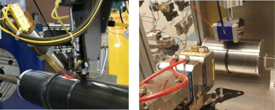
AFP setup with hot gas torch heating (left) and laser heating (right). 70
A focused IR lamp was developed first to augment and later to replace the nitrogen gas torches which had serious problems with reduced heat transfer in the nip region due to hot gas flow stagnation. IR lamps are characterized by being relatively low cost and very easy to control, so that careful regulation of the melt zone temperature is possible. They are very efficient heat sources when used on carbon-based materials since the energy is almost entirely absorbed. 93 However, IR heating has the limitation of not being able to provide highly focused energy which results in heating regions of the material that is not required to be heated. 84 Moreover, they are relatively slow to heat and cool and have the tendency to hold significant residual heat when switched off. 149 IR heaters were mainly used as preheaters 80,82,83,94,116,150 ; however, they were also used as the main heating source. 35,45,46,92 –94
Laser, as a heat source, has several advantages; it has the capability of focusing higher heat intensity at a localized point or to a precise region 77,109,127,128,151 which minimizes the induced stresses and the possibility of material damage. 77 Lasers are efficient and provide rapid heating due to the absence of convective hot gas delay and to the fast response time, 24,38,144,151 for example, a fiber laser (shown in Figure 2, right) was shown to be 50% more efficient than hot gas torch heating system, under same setup conditions, in terms of productivity. 70 Main disadvantages are being expensive in terms of initial purchase costs, 144 being physically large which limits the geometric complexity of parts to be produced, and that they require strict health and safety environments. 149
In the case of a CO2 laser (wavelength of 10,600 nm), the resin is highly absorptive, whereas with the new lasers, such as Nd: YAG and fiber (1064 nm wavelength) as well as diode (810→ 980 nm wavelengths) lasers, the resin is transparent. This means that utilizing a CO2 laser involves a high risk of burning and oxidizing the resin surface of the prepreg before affecting the adhesion of fiber–matrix interface. CO2 lasers are too bulky for direct mounting on a placement head. 10 Furthermore, their long wavelengths make them not suitable for fiber optic delivery due to their high absorptivity at these wavelengths. 10,84 The typical output of a CO2 laser is a small round spot, whereas a line or rectangular distribution is preferred so as to produce uniform heating across the width of the tape and substrate. 10 The round spot output of the source has been converted into line sources through the use of zinc selenide (ZnSe) lenses 73,74,77,84,107 –109,144 or galvanometer scanning. 75 These narrow lines make the process extremely sensitive to the laser position such that the bond quality is adversely affected by short dwell times. 10 On the other hand, the wavelengths of Nd: YAG, fiber, and diode lasers allow a different heating mechanism; the laser light is absorbed by the CFs, and since the CFs are highly thermally conductive along their length, a more uniform and controllable heating of the prepreg is achievable, thus eliminating the problem of charring or destroying the resin materials. 26,32,152,153 In general, diode laser systems are superseding the Nd: YAG lasers due to modular principles of optimized design and higher efficiency. 154 To the author’s best knowledge, there is no experimental work that addresses the heating mechanisms of the new lasers in terms of being transparent to resin so that heating occurs through conduction from the fibers to the resin. A qualitative study that characterizes this heating mechanism is thought to be necessary to reinforce the concept. This will help in understanding the importance and efficiency of the heat input in terms of the influence on the quality of the finished parts. Furthermore, it is worth to investigate the effect of the surface finish of the prepreg tows/tapes (roughness, resin-rich area, etc.) on this behavior as well as the interaction between the surface finish and the radiated energy on the overall performance of the fabricated parts. Such an investigation will help in a better optimization of the process in terms of temperature distribution profiles which affect most of the mechanisms involved in the tape placement process.
Near IR diode lasers have excellent characteristics, such as very compact, highly efficient, low maintenance, close process control, and very reliable. 32 They are widely utilized due to the much higher heat fluxes they can deliver which allow for higher placement rates. They can be fiber-coupled owing to their short wavelengths which allow delivery via light cables. Hence, large homogeneous rectangular spots can be produced by compact optical modules, resulting in uniform, progressive heating across the length and width of the tape which increases the dwell time and therefore the bond quality. 10,13,17,41
CO2 laser systems were studied in the period between 1980s and 1990s. A 80-watt CO2 laser system was very common. 72 –76,84,107 –109 A similar 65-watt CO2 was also investigated. 77,78 However, laser-assisted online consolidation was hindered due to lack of continuous-wave high-power laser systems and popularity of hot gas torch heating systems before being brought back around a decade later with the introduction of efficient and controllable laser systems. 20 Diode lasers were then dominant with several systems having different maximum powers ranging from 600 watt to 6000 watt. 9,13,19,22,23,32,40 –42,47 –53,66,126,128,131,132 A high-power ytterbium fiber laser heat source was being used 20,70 in which a set of optical beam shapers were used to convert the Gaussian profile of the beam into a nearly square top-hat shape. 155 A study on welding with high-power fiber lasers 156 as well as comparison with diode lasers in plastic welding are available. 155
Ultrasonic consolidation is a relatively new method to provide energy and pressure. Advantages include speed (short heating/welding times), low energy consumption, ease of automation, and potential for in situ process monitoring. 26,129,133,135,142,157,158 Pressure and vibration are exerted simultaneously by a sonotrode which converts a high-frequency alternating current into high-frequency vibrations. In order to concentrate the ultrasonic heat at the welding interface, triangular resin protrusions known as “energy directors” are often used. 26,133,158,159 –161 One of the major shortcomings of ultrasonic welding of thermoplastics is that it is, by default, a spot welding technique, 129 which means post-processing 26 is required. Ultrasonic heating was investigated for processing thermoplastic composites in general 129,133 –135,142,157,159 –164 as well as for tape placement processes. 21,26
More recently, Heraeus Noblelight introduced their new heating technology for composite manufacturing, Xenon flash lamp. It is an improved AFP heating solution, compared to IR and laser heating, characterized by being very powerful, possessing a rapid and close temperature control in which desired processing temperature can be reached very quickly, and having no strict health and safety requirements as in the case of lasers. Unlike laser or IR lamps, this technology allows short-duration pulses of energy to the target rather than heating it continuously. 150
ATP: Process versions
Laser-assisted ATP
Laser-assisted ATP (LATP) of thermoplastic composites has been studied for almost three decades. Beyeler et al. 84 started the basic concept of a continuous thermoplastic tape consolidation process with main objective being to achieve consolidation speeds of up to 1 in s−1 (approximately 25 mm s−1). Mazumdar and Hoa 77 suggested that accurate positioning of the laser beam is necessary to achieve the desired temperature distribution. However, the invisible nature of the CO2 laser beam, due to its long wavelength, makes it difficult to precisely position and align the beam. 84 Grove 113 highlighted that the arbitrary laser incidence angle of 15° does not enable the laser energy to be transferred to the nip region with optimum efficiency and that reducing this angle would result in direct irradiation being incident at points closer to the nip which means decreasing the maximum temperatures calculated at the surface. Agarwal et al. 108 presented a thermal analysis of a winding process and compared experimental process temperatures with those computed using a heat transfer model proposed by Beyeler and Guceri. 96 He found that only 20% of the laser energy is absorbed by the composite material which was attributed to the high incidence angle.
Comer et al. 23 conducted different experiments to compare the LATP process with the autoclave process using CF/PEEK prepreg. The laminates produced by LATP performed better than the autoclaved ones in terms of interlaminar toughness (134%) but less well in terms of flexural strength (68%), interlaminar shear strength (ILSS; 70%), flexural stiffness (88%), and open-hole compression (OHC) strength (78%). Ray et al. 22 reported results of similar trend and mentioned that the lower strength and stiffness values were partially attributed to the lower crystallinity exhibited by the LATP (18%) compared to autoclave processed laminates (42%) and higher toughness of the matrix in the LATP laminate. Using a diode laser and optimized parameters, Schledjewski and Miaris 165 reported a 94% bond strength of that obtained in an autoclave. Stokes-Griffin and Compston 39 found that an LATP can produce CF/PEEK laminates at 100 mm s−1 with a short beam shear (SBS) value matching those obtained by conventional methods. At 100 mm s−1, the SBS was found to be relatively independent of process temperature, except for very high temperatures (600°C) where a sign of degradation was noticed. At a placement rate of 400 mm s−1, however, the SBS increased with increasing temperature, and above 550°C the same level of SBS value of conventional processing methods was achieved. Stokes-Griffin and Compston. 17 investigated the possibility of sub-melting temperature (Tm) bonding below the melting point for CF/PEEK composites. They concluded that bonding occurred for consolidation temperatures lower than the melting point provided that the infinite Tm was exceeded in the heating phase, hence concluded that the assumption of a bonding temperature threshold of the melting point results in significant underestimation of strength. Stokes-Griffin and Compston 41 proposed a method to determine the required laser heat flux profiles to achieve desired heating zone temperature profiles by means of an inverse thermal model. A step shape temperature profile was shown to achieve the best bonding, whereas a two-stepped heating profile was found to provide a good balance of increased strength with a small increase in power requirement.
ATP with hot gas torch
The use of hot nitrogen gas as a heating source demonstrated good interply bonding in a tape winding process, although the required processing conditions are different from those of compression molding and autoclave processing. Due to the short melt times, a good interply bonding requires higher processing temperatures (above 600°C) so that sufficient molecular interdiffusion occurs. 79 ATP produced samples had mechanical properties of 45% less than the autoclaved ones, which suggested that with post-consolidation, the ATP processed composites would be acceptable for aerospace applications, but without post-consolidation, they might be suitable for commercial applications only. 55 Thermoplastic flat laminates using AFP machine were manufactured having tensile and compressive moduli higher, tensile strength at the same level, and compressive strength lower than autoclaved samples. 27 The NASA Langley HHATP process alone delivers 85–90% of the typical composite mechanical properties achieved when the HHATP process is followed by a standard autoclave process cycle. 101,141 By trying different tape materials, it was concluded that with the proper quality tape, HHATP can produce aerospace grade quality OOA in situ composite parts. 101,103 Many common optimization techniques were all ineffective in producing autoclave-level laminate quality due to the poor incoming tape quality. This was supported by results using the HHATP setup in which SBS from commercial APC-2/AS4 gave 76% of the SBS of an autoclaved laminate, 85% for experimental APC-2/AS4, and 105% for pre-autoclaved APC-2/AS4. 102,104 Hence, the most worthwhile development would be placement grade thermoplastic tows and tapes with tight control of thickness and width variation, low intraply and interply void content, uniform fiber/resin distribution, and a thin but finite resin-rich surface. 141 Dry repeated passes of the ATP head on the surface result in maximum and uniform bonding through the laminate. 31 Preheating the tool will help increase the bond strength, but since this is a costly solution, it was suggested to also carry out dry passes on the first few plies with a short duration between them, such that the localized temperatures are high enough to compensate heat sink effects. 31 Deconsolidation has a major role in the final volume fraction of voids. Multiple passes and quenching are two methods specified to control and prevent deconsolidation, especially in the top layers of a laminate. 30 One pass of the roller could be insufficient to produce good intimate contact and bonding. Degree of intimate contact increases with the number of passes and reaches nearly the value of unity after five passes. However, the SBS strength and modulus do not increase significantly with the number of passes. In fact, the modulus has the highest value for a single pass of the roller. 65 A high-quality laminate can be manufactured only with a certain combination of process parameters that do not activate the thermal instability. 38
Ultrasonic consolidation
Thermoplastic composite samples were ultrasonically welded with excellent success; tests for CF/PEEK composites showed almost 100% interfacial bonding strength relative to the matrix. 166 The process of ultrasonic welding of thermoplastic composites was modeled; it was concluded that the shape of the energy director is essential to the process with a rectangular director not providing enough heat, 163 hence triangular energy directors were then proposed to simulate the process. 164 The development of weld strength in ultrasonic welding thermoplastic composites with flat energy directors was investigated to determine whether and how the feedback from the ultrasonic welder can be used to optimize the process. 157 The use of very thin flat energy directors was proposed for a novel zero-flow welding technique capable of creating quality welds with little or no squeeze flow of the energy director. 129 Lionetto et al. 142 developed an experimental setup consisting of a filament winding machine, a horn, and a compaction roller to model the continuous ultrasonic impregnation and consolidation of thermoplastic composites. Compared to an earlier work by the same authors, 162 the compaction roller was added after the horn which enabled an increase in compaction time until cooling was completed. The produced samples had a shear modulus in line with that predicted by the micromechanical theory of unidirectional continuous fiber composites as well as a void content comparable with the values reported in literature. The feasibility of AFP using ultrasonic consolidation as an alternative to hot gas torch, laser, and IR heating was investigated. The results suggest that the ultrasonic heating is a potential technique that can be used to manufacture thermoplastic composites by automated tape/tow placement methods. 26 Chu et al. 21 compared GF/PP laminates, manufactured by ultrasonic vibration–assisted AFP (UAFP) and autoclave in terms of mechanical properties and crystallization. The experimental results revealed that the ILSS of the specimens from UAFP matched the hot-press ones, whereas mode I interlaminar fracture toughness and impact toughness of the UAFP specimens were 59.9% and 20.1% lower than the hot-press ones, respectively. These lower values were attributed to the lower degree of crystalline caused by the higher cooling rate during the UAFP process. Moreover, the degree of crystallinity for the UAFP specimens was 38.5% versus 49.2% for the hot-press ones.
Process modeling
Processing of semi-crystalline thermoplastic composite material via tape placement involves heating of the incoming prepreg tape and substrate material above the melting point of the matrix, consolidation which promotes intimate contact between the incoming tape and substrate at the nip point as well as diffusion of polymer chains across the interface to build interface strength, and solidification which involves crystal formation and growth upon cooling below the T g to develop full mechanical properties. 23,167 Hence, the overall quality of manufactured parts in a thermoplastic tape placement process is influenced by several mechanisms, such as intimate contact development, autohesion or healing, bonding, void consolidation, void growth (deconsolidation), thermal degradation, generation of residual stresses, crystallization, and melting kinetics. Most of these mechanisms are highly dependent on the thermal history during the process. 10,20,25,33,37,41,48,60,62 Therefore, the heat transfer model is the main model and is the first model to start with as part of the process modeling with the resulting temperature history/distribution to be used as input for the other models (refer to Figure 3). 150 However, before presenting these different models, it is useful to discuss about the compaction roller as it has a direct influence on some of the process models, such as heat transfer, intimate contact, and void consolidation models.
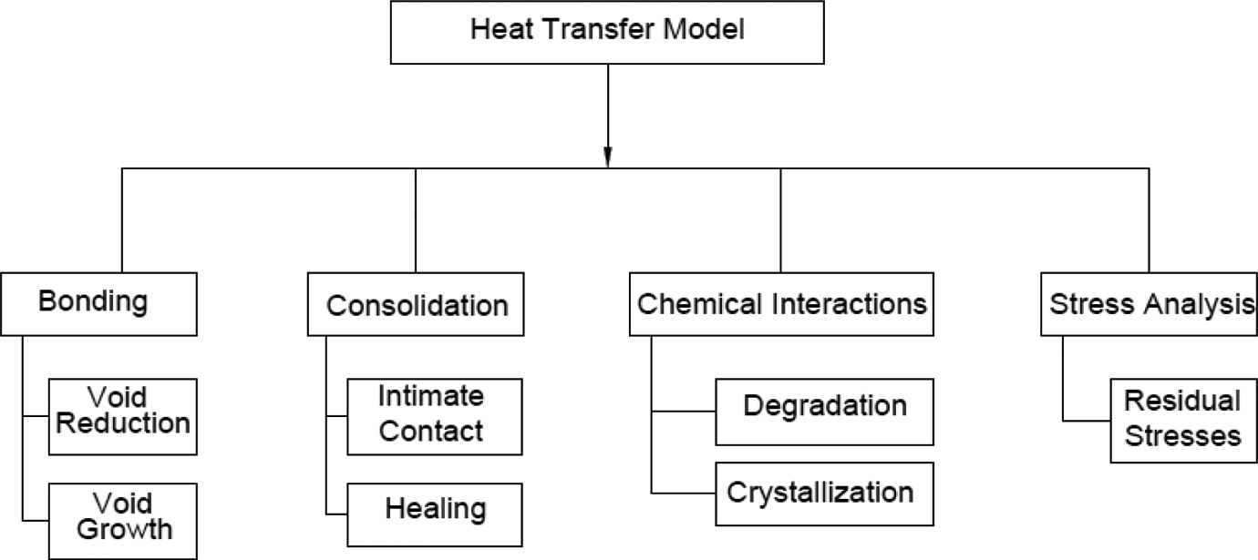
ATP process models/mechanisms showing relation with heat transfer model.
Compaction roller
In a tape placement process, the selection of the compaction device plays an important role in the mechanical properties of the finished parts. The compaction device could be a single roller, multiple rollers, or an area compactor. Setups having area compactors 101 –104,139 –141 as well as two compaction rollers 25,30,31,33,43,47,53,57 –59,69,138,148 were investigated. The single roller design, however, is by far the most common available setup in the literature. 10,12,13,16 –19,22 –24,27,31,39 –42,44,50,53,54,62,64,66,73,75,79 –84,95,96,105,109,128,130 –132,136,143,147,148,168
Systems with single roller, however, may potentially suffer from voids especially in the last few layers of the part; hence, application of extra passes can reduce these voids, but then the process productivity will be adversely affected. The advantage of a multiple-roller setup, although results in complex design, is that the second roller serves the function of a repass as compared to a single-roller setup. 27
The most common material used for compaction rollers is steel 20,25,30,31,33,36 –38,43,44,54 –56,61 –64,73,74,79,81,84,95,105,109,130 –132,136,138,142,143,147,148,150,168 with stainless steel grade being specified in few works. 19,27,127,128 Some enhancements in the placement process were achieved by introducing silicone rubber rollers which can be used on complex shapes due to their high deformability. 10,38 In the recent years, silicone rollers are more widely used. 10,13,16,17,22,23,39 –42,48,50,53,66,131,169 Stokes-Griffin and Compston 17 compared a silicone rubber (conformable) roller with a brass (rigid) roller. The conformable roller was found to have a much longer pressure distribution which resulted in more time being available for the development of intimate contact. Furthermore, the rigid roller casted larger shadow which resulted in more cooling prior to the nip point. This led to lower consolidation temperatures which negatively affected the bond strength. Rigid metallic rollers were either approximated as a convective boundary condition with varying heat transfer coefficients 37,60,62,64,96,108,113 or considered as a fixed boundary temperature. 30,31 However, with the silicone rubber, it was modeled as a physical body and its relative influence on the thermal history of the process was analyzed. 10 With the silicone rubber being highly deformable and the laminates usually thin compared to the roller dimension, the deformation of the roller could be determined by assuming a roller compaction on a flat rigid surface. 53 Tannous et al. 131 investigated the material of the roller on the roller/tape friction in a thermoplastic tape winding process. Results showed that the silicone roller held the tape firmly and made it follow the mandrel rotations with minor sliding, whereas with the steel roller and much lower friction forces, the slipping rate was very high.
The size of the roller has a direct effect on the productivity of the process as bigger rollers have higher deposition rates. Sarrazin and Springer 18 studied the effect of roller diameter on stresses. For the range of roller diameters used (50—200 mm), the size of the roller was found to have little effect on the stresses. They suggested that outside this range, much smaller diameters would affect the stress distributions, but thought that such small rollers would be impractical. As for roller cooling, both air cooled 20,70 and water cooled rollers 19,48,150 were reported.
Heat transfer model
In general, the tape placement process is a 3-D transient process. However, few studies considering the 3-D behavior of the process have been performed. Toso et al. 147 implemented a 3-D transient model for the tape winding process. They assumed that the flow in the vicinity of the hot gas torch is not laminar and that the measurement system must smooth its turbulent variations. More recently, Jeyakodi and Shroff 99 used a 3-D transient model for the laser-assisted AFP process with the inclusion of the tool return time during which the placement head does not return to the location where the section of the tape was placed. Few other 3-D transient models were also being simulated. 9,102,150 Using a Eulerian frame of reference attached to the placement head with a roller moving at constant speed, the transient nature of the tape placement in a Lagrangian framework is transferred to a steady-state problem. 18,35,44 –46,62,93,95,96,100,105,108,113 A 3-D steady-state model for ATP 100 and filament winding 92 was implemented.
Many assumptions were introduced to simplify the problem from a complicated 3-D version into a simplified two-dimensional (2-D) version or to a more simplified one-dimensional (1-D) problem. Some of these assumptions include tape and substrate are heated uniformly across the width, 10,36,60,62 composite is anisotropic yet homogeneous continuum, 60,62,64,96,113 transverse thermal diffusivity or conductivity is low, 10,36,62,96,143 length is large as compared to width and thickness 18,60,143 or with respect to the local heat source, 68,84,96,113 plane strain assumption is considered since width is much larger than thickness, 18,61,64 heat loss through edges is negligible, 62,113,143 primary transport mode is laminate motion rather than thermal diffusion, 10,30,62,96 and inertia effects are neglected due to high viscosity of matrix resin 68 or due to slow velocity of the roller. 61
A 2-D transient model for tape winding and press molding was developed using cylindrical and Cartesian coordinates, respectively. 119 Another 2-D nonsteady model was implemented using a space-fixed coordinate system, with the position of the roller modified during each time step. 84 Many other 2-D transient heat transfer models 18,19,25,33,67,111,136,142,170 as well as 2-D steady-state models 10,35,40,44,46,47,53,54,61 –63,85,95 –97,105,108,127,128 were reported. Kim et al. 64 used a 2-D steady-state model, however, suggested that a detailed analysis considering a 3-D model is necessary due to the nonuniform hot gas impingement condition. Weiler et al. 71 presented a 1-D transient model of a laser-assisted winding process and considered heat accumulation (heat reaching the back of tape or substrate) as a key phenomenon for the process, suggesting this effect needs further analysis and investigation. More 1-D transient models were reported 36,37,43,71,82,110,143 as well as 1-D steady-state gas impingement models. 30,31,138,148 It is obvious that most of the simulation works are based on 2-D and 1-D models with major assumptions being adopted. For example, uniform heating across the width can be easily accepted for a heat source that can be highly controlled such as a laser, but it poses doubts when dealing with a hot gas torch system as in the studies by Khan et al. 36 and Tumkor et al. 60 These thermal models, as will be illustrated later, constitute the inputs for most of the other process models; such assumptions hence affect the results and conclusions made for ATP processes. It is thought that more 3-D modeling works are necessary to verify and validate the ATP process under wide range of actual process conditions.
Heat transfer due to crystallization melting/solidification was considered negligible when compared to conduction heat transfer through material by some authors. 25,33,95 Others neglected this term due to the overestimation of temperature at the nip point it produced for high heating rates. 37,147 However, many others included this heat generation term in their analyses. 9,10,18,19,40,44,62,63,67,92,96,108,111,119,127,128,136,150,169 A typical 2-D steady-state (with respect to the moving frame) model with heat generation has the following form 44,62

where T is the temperature, kL and kT are the longitudinal and transverse thermal conductivities of the prepreg material, respectively, ρ the density, mm the mass fraction of thermoplastic matrix in the prepreg, Hf the heat of crystallization, V the line speed, cm the fraction crystallinity, and Cp the heat capacity. On the other hand, a 1-D steady-state gas impingement model neglecting the heat generation term will have the following form 30,31
where α is dependent on the thermal properties of the material in the through-thickness direction, V is the process velocity, τ is the time, and x is the location on the surface.
The majority of thermal modeling of LATP considered uniform heat fluxes applied to tape and substrate as boundary conditions. 10,19,20,62,63,66,96,108,113 The effect of a shadow under the roller was not considered until recently with one exception being the work of Grove 113 who performed 2-D ray tracing calculations to determine the heat flux distribution. Recently, the shaded areas were considered by simplifying radiation as a uniform heat flux over the illuminated regions only, 10 the interaction between light and shaded areas was investigated in an attempt to determine their influence on the temperature history, 40 and an optical ray tracing model was also developed to have a detailed estimation of the irradiance distributions. 13
In the numerical analysis of the heat transfer models, different solution techniques were implemented. The proper generalized decomposition technique was selected over finite element method (FEM) to solve the heat transfer model. 47,100 To overcome the complexity of the problem, a mapping technique which combined the flexibility of FEM with the simplicity of the finite difference methods (FDMs) was used. 96 FEM was the most common technique being followed 9,10,18,19,26,8,40,54,62,64,72,95,99,102,105,110,113,116,117,119,136,142,147,150 with FDM 35,45,46,53,60,82,92,93,97 and finite volume method (FVM) 48,67,105 being used as well.
Intimate contact model
Different intimate contact models were developed in an attempt to characterize the degree of actual contact between the two surfaces to be bonded together. Initial physical contact is due to the inherent asperities in the thermoplastic tapes. At the application of high temperature and pressure, the viscous behavior of thermoplastics allows the surfaces to deform until full contact is reached. Hence, the parameters that influence the amount of intimate contact are the initial tape surface geometry, temperature, pressure, and time. The most important step in modeling the intimate contact is the geometric representation of the thermoplastic prepreg surfaces. 12,91,171,172
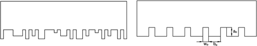
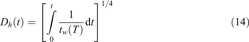
Dara and Loos 14 developed an intimate contact model based on an irregular surface being described as a statistical distribution of rectangles having different heights and widths (Figure 4, left). The degree of contact was calculated using the average distribution of the dimensions through a viscoelastic squeeze flow model of the composite melt. This model was complex in its formulation, hence Lee and Springer 118 simplified it by considering a series of rectangles having the same size (height ao and width bo) separated by equal gaps of width wo (Figure 4, right). With this simplification, they proposed a 1-D Newtonian (laminar) flow of the asperities (rectangles) into the gaps. The geometry of the rectangles was determined and adjusted so that the model agreed with the experimental data. They defined the degree of intimate contact as the fraction of the interfacial contact area. In developing the model, they considered the applied pressure and viscosity as constant, independent of time, hence the degree of intimate contact had the final form as follows
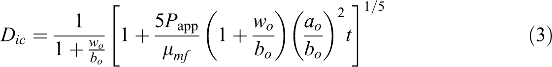
where Papp being the applied pressure, μmf the matrix–fiber viscosity, and t the time. They assumed that a full intimate contact is achieved when Dic reaches the value of 1. This version of the model was used by few authors. 122,143 Mantell and Springer 119 upgraded this model to a more generalized form by considering both the applied pressure and viscosity as time dependent, hence
where tc is the contact time during which pressure is applied. This version was later used in some other works. 31,49,134,135,173 Mantell and Springer 119 suggested that, frequently, the second term in the square bracket in equation (4) is large compared to unity. Hence, they came up with an approximate version of their generalized model having the following form
in which the value of
Schematic surface representation of Dara and Loos (left) and Lee and Springer (right) intimate contact models.
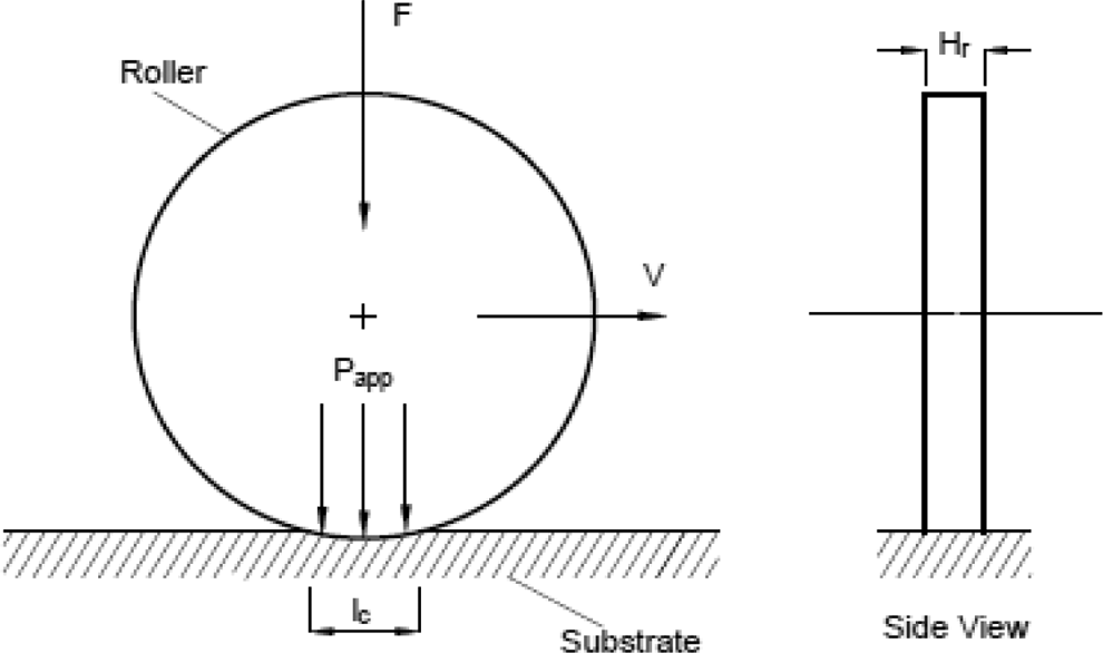
Interaction of the rigid roller with the substrate.
For the tape laying setup, the degree of intimate contact was formulated as follows
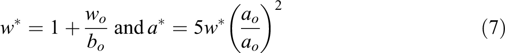
where F is the applied force of the roller, V is the translational roller speed, and Hr is the tow/tape width. To derive equation (6), they considered a rigid compaction roller as shown in Figure 5, and assumed the length lc is so small, so that the temperature along it is constant, which means the viscosity is constant as well. However, the accuracy of this assumption when using a silicone rubber roller is doubtful. The silicone roller will have a longer contact with the substrate, so that the assumption that the temperature, and hence the viscosity, under this larger contact length is constant, is most probably not accurate and needs reevaluation and validation. Tierney et al. 138 used the approximate model (equation 5) for AS4/PEKK but still used the same constant of 0.29 applicable for CF/PEEK.
Pitchumani et al. 25,33 followed the same approximate model but used the actual profiles of pressure and temperature under the roller obtained from the consolidation and thermal models, respectively, rather than an average roller pressure and an isothermal field. This approximate model was widely used in the literature. 4,16,17,43,63,65,85,99,117,136,148,174 Butler et al. 69 suggested that the Mantell and Springer’s general model can be used for short processing times, whereas the approximate version of the model is good for long processing times.
Care should be taken when adopting this approximate model. In fact, Mantell and Springer produced plots showing the value of this second term in the square bracket for tape laying process for different tape widths as shown in Figure 6. The plots show that this term is high for slow speeds and decays as speed increases up to 5 in s−1 (approximately 125 mm s−1). For example, for a tape width of 0.25 in (6.35 mm), the value of this term goes from approximately 31.0 for 1 in s−1 (approximately 25 mm s−1) to a value of 6.0 for 5 in s−1 (approximately 125 mm s−1), whereas for a tape width of 0.5 inch (12.7 mm), the values are 15.5 and 3.0 for speeds of 1 in s−1 (approximately 25 mm s−1) and 5 in s−1 (approximately 125 mm s−1), respectively. This suggests that at higher speeds, the assumption has to be investigated on case-to-case basis, especially that other variables such as force, thickness and interface temperature play a role as well. More recently, the investigated process speeds in ATP are much higher and reached 800 mm s−1. 66 It was found that some works used the approximate version of the Mantell and Springer model although the investigated speeds were high. For example, Stokes-Griffin and Compston 16 used this approximate model while placement rate was 200 mm s−1 (approximately 8 in s−1) and tape thickness 12 mm (approximately 0.5 in); the value of the term for one of the cases in the study was estimated to be around 4, which is not large enough when compared to 1 so that 1 can be taken out. The same doubt goes for another work by Stokes-Griffin and Compston 17 where investigated speed reached 333 mm s−1 with 12-mm tape width. It is suggested that this has to be investigated in advance before adopting the model on case-to-case basis and that the data are reported so that the level of accuracy is known for the investigated case.
Value of dimensionless parameter for ATP process.
In lieu of micrographs used by the original authors to determine the model parameters, different other techniques were followed. A least-square fitting method to minimize the error between the model and the experiment 122 and confocal microscopy to characterize the surface roughness of the tape 49 were used, whereas others adapted the parameters from the literature. 134,135 Hence, this model suffers from a fundamental problem as the geometric parameters are estimated by fitting the model to experimental data. 12,174
The profilometric scans of an AS4/PEEK prepreg show that the surface structure is random and the roughness features can be found at a large number of length scales, which suggest that a fractal geometric description of the thermoplastic material surfaces is more appropriate. 91,171,172 Yang and Pitchumani 172 proposed a more sophisticated illustration of the prepreg surface as compared to the rather simplified approach of identical triangles. They modeled it as a Cantor set fractal surface having multiple generations of asperities with decreasing height (refer to Figure 7). Through a squeeze flow model, the smallest asperities of the highest order generation were squeezed first keeping the larger asperities of the lower order generation undeformed. After the highest generation gaps are filled, the next generation of asperities begins to deform. This process continues until the gaps of the first generation are filled and hence full contact is achieved. The development of intimate contact for the nth generation of asperities is given by
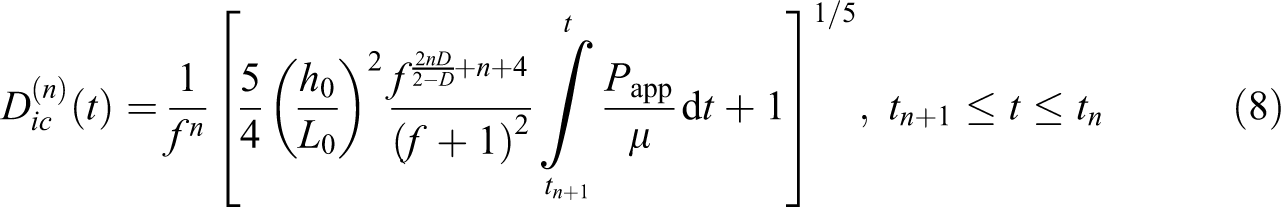
where D is the fractal dimension of the surface, f the scaling factor, ho the height of the first generation asperity, and Lo the total horizontal length of the Cantor set block.
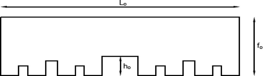
Schematic representation of tape surface for intimate contact model of Yang and Pitchumani.
In the development of this model and in order to simplify the analysis, an equal scaling was implemented in describing the lengths and widths of the asperity elements in the Cantor set block. Warren et al. 175 proposed a more generalized representation based on different scaling factors along the length and height of the Cantor set, respectively. The simplification was reinforced by measurements of the different scaling factors being found very similar of actual thermoplastic tow surface profiles. 172 Using surface profile measurements to directly obtain the surface parameters is a notable advantage to this model; however, since the fractal characteristics exhibited by the surface may not be necessarily true for all tape materials, this model may not be applied generally to all tape materials. 176 Yang and Pitchumani’s fractal model was used in different research works. 17,36,38,41,146,167,177
In an attempt to obtain a quantitative contact characterization, Schaefer et al. 176 investigated experimentally the degree of intimate contact between CF-reinforced polyamide-6 (PA-6) tapes. They found that intimate contact develops within seconds when temperature is slightly above Tm and applied pressure in the range of 1–4 kPa and that the model of Mantell and Springer as well as that of Yang and Pitchumani generally overestimate the time needed to reach full contact although the Mantell and Springer model is more conservative. They suggested that this could be due to the fact that the PA-6 tape has relatively low viscosity and possesses a resin-rich layer near the surface which might have affected the contact development process. A resin-rich layer was also assumed to be close to the bonding surface. 31 This resin-rich layer has many advantages; it allows resin flow and chain entanglement during the online consolidation process, promotes intimate contact between the tape and substrate in the consolidation process, and possibly reduces the entrapment of interply voids when compared to a resin poor surface. 55
Viscosity is an important parameter in the intimate contact models, presented above, and is found through an Arrhenius-type relation. Some authors used the fiber-matrix viscosity in their analyses, 38,65,118,119,172 whereas others used the neat resin viscosity. 49,134,135 The viscosities of fiber–matrix mixture and neat resin can differ by orders of magnitude. 176
Incomplete or bad bonding between layers means the existence of air gaps between layers and hence a thermal contact resistance exists 47 which should be considered in the thermal simulation. 122 This thermal resistance quickly decreases with increasing degree of intimate contact. 71 Thermal contact resistances were investigated in several works. 35,48,64,71,99,100,178 On the other hand, a perfect contact was assumed due to the very smooth surface of the tape and the considerably high compaction pressure. 10 Finally, a constant degree of intimate contact was considered. 66
Autohesion (healing) model
Autohesion (or healing) is a self-diffusion process between two similar thermoplastics put in contact. During the process, interdiffusion of polymer molecules occurs across the interface of the two surfaces. With time, more diffusion takes place leading to an increase in the bond strength. 14,118,179 Autohesion commences when the temperature is brought above the T g or above the Tm for amorphous or semi-crystalline polymers, respectively. 17,31,137 De Gennes developed the reptation theory to describe the motion of an individual linear polymer in an amorphous bulk under isothermal conditions. This theory was extended by Wool and co-workers to describe the strength development process 137,177 as shown in Figure 8.
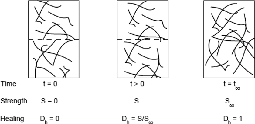
Illustration of the autohesion (healing) phenomenon.
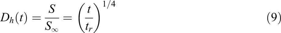
The degree of healing under isothermal conditions, as formulated below, can be found in different works 14,69,117 –119,136,137,177
Bastien and Gillespie 180 extended isothermal healing to nonisothermal fusion bonding of amorphous thermoplastic laminates by dividing the thermal history into equal time intervals in which the temperature is assumed constant and equal to the average temperatures between two consecutive times. They suggested that this procedure can be applied to any arbitrary thermal history provided the time step is sufficiently small to yield converged results. Agarwal 107 applied this nonisothermal model to PEEK-based thermoplastic composites by introducing a shift factor aT applied to the reptation time tr at a reference temperature Tref
This model was then adopted by others. 4,25,33,43,13 8 Sonmez and Hahn 63 modified the isothermal reptation model in a similar fashion to Bastien and Gillespie 180 in order to formulate the nonisothermal healing during tape placement of thermoplastic composites incorporating an integral through the following expression for the degree of healing
Yang and Pitchumani
137,177
considered that the models of Bastien and Gillespie
180
as well as Sonmez and Hahn
63
being inaccurate in that considering the process to be isothermal at average temperature for each time interval is not accurate in the actual process. They also pointed to another limitation of these two models when using the reputation theory; according to Wool and co-authors, the expressions of both models are valid only for low molecular weights, M, in the range of
This was, then, used to come up with a degree of healing for a general nonisothermal healing model
Arrhenius-type relationships were used to determine the welding time (tw). 31,38 Yang and Pitchumani 177 compared their nonisothermal healing model with the models of Bastien and Gillespie and Sonmez and Hahn. They found that these models overpredicted the healing development rates, with Sonmez and Hahn model producing closer results to the exact solution. Tierney and Gillespie 31 found that Yang and Pitchumani model correlated better than Bastien and Gillespie model with experimental results. The Yang and Pitchumani model was also used by many others. 16,17,36,38,41,137,146,167,177
Bonding model
The main goal of bonding is to produce a uniform structure by intimate contact and molecular interdiffusion. Intimate contact is a prerequisite for autohesion, in the sense that the two surfaces have to be in intimate contact for autohesion to proceed across their interface. Hence, the degree of bonding is formulated based on a coupled bonding model which takes into consideration both the phenomena of intimate contact and autohesion. 16,17,31,39,41,171,172,177 At autohesion time, full strength is achieved. Time to reach intimate contact is influenced by the surfaces-in-contact roughness, the applied pressure, and the interface temperature. In slow processes, such as compression molding and resistance welding, the autohesion time can be ignored because the processing time is much longer. On the other side, in processes such as online consolidation (ATP) and hot plate welding, the surfaces are already at high temperature when they get in contact; hence, autohesion time could be on the same order of intimate contact time and must be considered in determining the degree of bonding. 87,180 Complete interlaminar strength is achieved when intimate contact is fully developed followed by sufficient healing. 39
Maurer and Mitschang 19 proposed a simple bonding model for isothermal process

They suggested that in processes where intimate contact is much slower than autohesion, healing occurs instantaneously (i.e. Dh = 100%); hence, the model reduces to

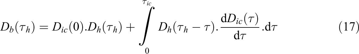
Butler et al. 181 presented a coupled bonding model in which the degree of bonding is defined as the area average of bond strengths of each of the incremental areas that come into intimate contact through the duration τic of the applied pressure. 33,63 The expression for the degree of bonding was formulated based on convolution integral. It appeared in a full form containing the contribution by the area in intimate contact at the beginning of the bonding process as follows 4,17,41,69,177
where

Butler et al. 69 developed a dimensional parameter (Ω), which is the ratio of time scale for full healing to that of intimate contact, to determine whether a bonding process is healing controlled (Ω > 1), intimate contact controlled (Ω < 1), or equally dominated by both. An evaluation of this dimensional parameter revealed that in the tow placement process (time-varying temperature and pressure), both mechanisms are controlling, whereas a resistance welding process (isothermal and constant pressure process) was shown to be intimate contact controlled. Yang and Pitchumani 177 followed a similar approach by introducing a dimensionless parameter termed as “fusion bonding number, fb” used in identifying the controlling mechanisms for AS4/PEEK prepreg material. Lamethe et al. 169 found that interdiffusion across the interface and crystallization are key parameters for the strengthening of the interface in a thermoplastic ATP using APC-2 tows, however, didn’t include intimate contact in their analysis due to the extremely low roughness of the prepared samples. Tierney and Gillespie 31 as well as Yang and Pitchumani 137 assumed that bonding occurs as long as the processing temperature is above the melting point of semi-crystalline polymers, whereas Stokes-Griffin and Compton 17 considered that sub-melt bonding is possible for lower temperatures up to the T g (taken at 143°C).
Ageorges et al.
117
proposed a transient model based on the stepwise simulation to determine the degree of bonding for the resistance welding of thermoplastic composites. This model was later used by Khan et al.
36
In this model, the evolution of the local degree of intimate contact
August et al. 5 suggested that these models lack accuracy due to exclusion of some factors, such as shear thinning of polymer which is usually caused by extremely rapid application of pressure. Narnhofer et al. 167 verified the assumption of a Newtonian shear flow in these models considering that thermoplastics normally undergo shear thinning at higher shear rates. They found that the assumption of Newtonian shear flow, generally, results in underestimation of the velocities and an overestimation of the pressure.
Void dynamics model
Thermoplastic composite tapes available on the market contain a certain percentage of voids. When the tape is subjected to heat, the matrix softens and the internal pressure of the voids can cause them to grow. When compaction pressure is applied at the nip point, the voids will be compressed. If cooled sufficiently before the consolidation pressure is released, then voids expansion can be ceased. 12
Void consolidation model
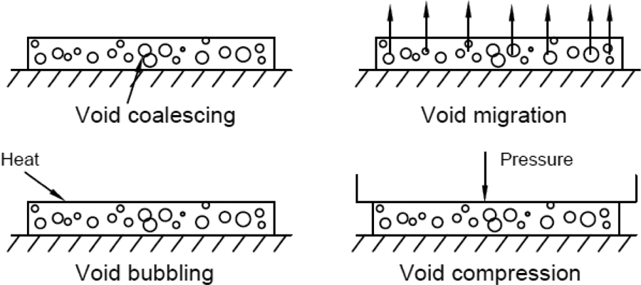
Two types of voids exist in laminates, namely interlaminar voids and intralaminar voids. Intralaminar voids mainly originate from the input material, whereas interlaminar voids are a result of ATP processing and are difficult to remove from finished parts. 98 Interlaminar voids were covered through the different intimate contact models presented earlier. Ranganathan et al. 68 described the four mechanisms that constitute the intralaminar void growth/collapse and transport as shown in Figure 9: (1) void coalescing, when two or more voids meet forming a bigger void; (2) void migration, mainly due to fluid pressure gradient; (3) void bubbling is void reduction due to cooling; and (4) void compression, due to application of compaction pressure. In their model, they ignored void coalescing, neglected void migration relative to resin due to resin high viscosity, used a macroscopic flow model to handle the void transport within the resin, and used a microscopic model to account for void bubbling and compression.
Void mechanics in in situ consolidation process.
Upon applying heat and pressure to achieve consolidation, the fibers and matrix move together; hence, they modeled the consolidation through a squeeze flow of compressible viscous continuum. They made other assumptions such as considering the continuum to be compressible, including thermal effects on viscosity, assuming viscosity didn’t alter the fiber volume fraction and the void fraction during the process, and that the tow consisted of fibers aligned in one direction leading to a transversely isotropic fluid model. The models predict the final void fraction and final thickness of a composite part. The 2-D macroscopic void transport model based on time-dependent squeeze flow is given by
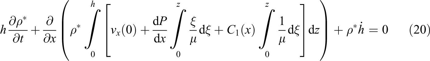
where h is the thickness of the tow, ρ* is the density of the fiber–resin–voids mixture scaled with respect to the density of the mixture without voids, t is the time, x is the dimension across the tow width, vx is the flow velocity across the tow width, P is the pressure, ξ is a dummy variable of integration, µ is the viscosity, and C1(x) is a constant of integration. On the other hand, a single void is represented by a sphere of radius R surrounded by another sphere of radius S representing the melted resin fluid. The local void fraction at time t is described by the ratio of R and S, which is governed by a balance between the void internal and external pressures, the surface tension σ, and the melt viscosity µ. Hence, the microscopic void consolidation model is formulated as follows
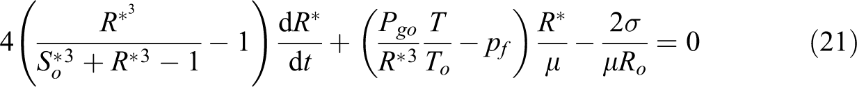
where R* and S* are normalized by the initial void radius Ro, and Pgo and To being the initial void pressure and initial temperature, respectively.
By solving these two models (equations (20) and (21)), it is possible to obtain the rate of void growth/collapse at various locations in the domain. They used the general formulation of the model to solve for three specific cases: (i) isothermal incompressible, (ii) isothermal compressible, and (iii) nonisothermal compressible. They found that the nonisothermal compressible model best applies to the thermoplastic tow placement process. These models produced similar results to experiments 37,69 or were used as a consolidation model in the parametric study of thermoplastic tape placement process. 36
As opposed to the squeeze flow model considered above for thermoplastics due to their high viscosity, processing of thermoset matrix composites (e.g. autoclave processing) allows the consolidation to be modeled as flow of resin through a porous network of fibers using Darcy’s law owing to the low viscosity experienced prior to the start of the curing process. 33 Zhang et al. 182,183 also used Darcy’s law to investigate and analyze void reduction during oven vacuum bag (OVB) processing of thermoplastic composites. They considered that void air removal during OVB processing of thermoplastic composites depend on air diffusion and interlayer permeability. Air is first diffused from the fully enclosed voids within a prepreg layer into a permeable interlayer region formed by two adjacent prepreg layers having surface roughness and is then transported through the permeable interlayer to the outside through the part perimeter which is open to the vacuum source. This air permeability was investigated based on a 1-D Darcy’s flow. OVB processing of thermoplastic composites, if proved feasible, will provide a lower cost alternative technique to the well-established but costly autoclave processing. 183 However, more effort is required to check the feasibility of applying such mechanisms to AFP and ATP processes.
Void growth (deconsolidation) model
Pitchumani et al. 25,33 modeled void consolidation as a squeeze flow of a compressible fiber–resin–voids mixture under the compaction rollers, following Ranganathan et al. 68 macroscopic and microscopic models. As for the void growth in the regions outside the consolidation zone, they described it as the expansion of the voids in a quiescent polymer melt at ambient pressure and tow temperature. Hence, the higher internal void pressure, resulting from exposure to elevated temperatures under the rollers, results in voids growing in size. Moreover, they considered the tow surfaces unconstrained and the matrix melt incompressible, so that void size increase led to an increase in the tow dimensions. They suggested that the analysis of void growth doesn’t need the macroscopic model equations to be solved since the fluid pressure is known (the ambient pressure). Therefore, using Patm instead of Pf, the change in void dimensions can be determined solely by the microscopic model equations. The instantaneous void fraction for the concentric void-resin shell model will then be
Considering that the tow to be attached to the substrate along its width, they suggested that the increase in tow volume due to void growth simplifies to an increase in tow thickness increase according to

Tierney and Gillespie 30 implemented the above mentioned void consolidation and growth models and found that they produce good correlation for through-thickness void fraction gradients with experimental results. They observed that deconsolidation has a major role in the final volume fraction of voids and that multiple passes has a critical role in reducing void content within the laminate. They also suggested that other methods such as quenching of the surface material immediately after the consolidation roller could be used to prevent deconsolidation in the top layers. Kok et al. 98 developed a method to analyze the consolidation state after the heating step of a laser-assisted fiber placement (LAFP) prior to the nip point. They used shims to reduce the consolidation pressure to obtain a representative state of deconsolidation, and then prepared multiple samples ranging from being well consolidated to completely deconsolidated. They suggested to use the data of the matching sample to come up with a more accurate model for the development of intimate contact.
These void dynamics models were developed and used for setups involving a rigid compaction roller 25,30,31,33,36,37,68,69 as shown in Figure 10. To the author’s best knowledge, these models were not used by any other researchers that have silicone rubber compaction rollers installed in their setups. It is necessary to validate these models with systems involving conformable rollers.
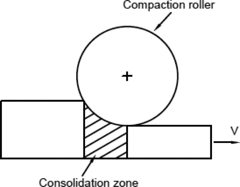
Consolidation zone under rigid roller.
It is believed that with a silicone rubber roller, these models will not predict the final void fraction accurately and most probably need to be modified. The geometry of the contact region between the roller, the tape and the substrate will be different in case of a conformable roller. For example, if we assume the contact will take the shape of a slender strip having a circular part with the tape and a straight part with the substrate as shown in Figure 11, then the distance and time of contact with the roller will be different than the case of a rigid roller. Taking these into considerations, the formulations of the model could be different and expected to provide different results.
Contact of silicone roller with incoming tape and substrate.
In a recent study, Zhang et al. 184 suggested that average void content is not the only factor that greatly affects void consolidation. There are other factors such as the distributions of void size, shape, and location. Hence, they conducted a detailed study to quantify the statistical distribution of void content, void length, equivalent void diameter, and void aspect ratio using a substatistical representative volume element for each void property. The majority of voids were found to be rod-like with varying aspect ratios, thus suggesting that the use of spherical void model for void dynamics is not appropriate to the voids in the prepreg tape under investigation (APC-2/AS4). 184
Thermal degradation model
Thermal degradation is one of many phenomena experienced in the in situ consolidation of thermoplastic composites. 25 Due to the low transverse thermal conductivity of fibers, it is a challenge to quickly melt the matrix of the incoming tape without degrading the matrix on the surface. To overcome this, it was suggested to allow for a longer heating period so that the heating power absorbed by the surface can be reduced. 83 On the other hand, higher temperatures reduce the viscosity and increase the rate of healing, thus are more favorable for processing. 39 However, prolonged exposure of the polymer matrix to elevated temperatures could lead to degradation and decomposition of polymer matrix. 25,85 Besides degrading the mechanical properties, thermal degradation also affects consolidation badly. Thus, the processing time should be adjusted depending on temperature according to the recommendations in Table 1. 62
Suggested maximum exposure times at various processing temperatures for CF/PEEK composites in nonoxidizing environments.
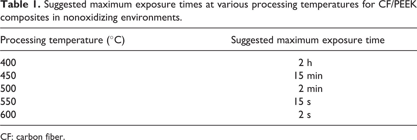
CF: carbon fiber.
August et al. 5 suggested that polymer degradation is exaggerated. Day et al. 185 investigated the influence of heating rate on the degradation of PEEK composites. They found that when heating rate increased from 0.01°C min−1 to 10°C min−1, the degradation temperature was also increased from 415°C to 550°C under nitrogen atmosphere and from 325°C to 560°C in air.
Material weight loss as a measure of thermal degradation in thermoplastics is very common and being used widely. 25,62,63,85,185,186 The other mechanism is crosslinking or chain branching which is considered in a degradation model developed by Nicodeau et al. 67 Nam and Seferis 186 developed a generalized composite degradation kinetics model based on material weight loss. The model is based on kinetic parameters found by isothermal experiments under nitrogen atmosphere; however it can accurately predict both isothermal and nonisothermal conditions using the same constants and identical reaction mechanisms without any additional assumptions. The degree of degradation is defined such that it lies in the range 0 ≤ α ≤ 1, with α = 1 corresponding to 36% weight loss. The model equations are as follows

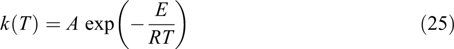
where w1 and w2 are weight factors and k is a rate constant determined through an Arrhenius-type relation
Sonmez and Hahn 62 adopted this model to predict the degradation weight loss in the tape placement process. They neglected the additional degradation due to oxidation, and hence suggested the model can be used regardless of the heat source type in the tape placement process. The Nam and Seferis model was used by many other authors as well. 25,43,63,85
Residual stress model
Of the main issues in the manufacturing of thermoplastic composite parts is the buildup of residual stresses resulting from the volumetric changes during solidification/crystallization. In thermosets, this is severe especially in thick parts due to the exothermic reaction and heat diffusion limitations. However, since melting and solidification of the thermoplastic matrix is highly localized, the online consolidation reduces the residual stresses which in turn lead to improved dimensional stability and better performance. 35,46,75 –77,109
Large thermal gradients during the in situ thermoplastic ATP and the mismatch of thermal properties between the fiber and the matrix are the other main factors that allow the development of residual stresses. 12,79,85,95 Residual stresses have significant impact on the mechanical properties and the geometry of manufactured parts. 100,178 If exceeding allowable limits, they may cause delaminations, matrix cracking, and distortion 12,79,80,85,95,100 as well as fiber buckling or void formation during solidification. 114 To get rid of distortion, for example, it was suggested to heat the mandrel above Tg while the plies are being laid and then cool everything at once. 27 Sonmez et al. 95 also mentioned that as temperature of the layers exceed Tg, annealing will arise and the residual stresses developed during previous tape placement will relax.
Parlevliet et al. 187 –189 presented a literature review about residual stresses in thermoplastic composites. They identified and discussed the factors responsible for the buildup of residual stresses, 187 outlined the experimental techniques to determine the magnitude and distribution of these stresses on various mechanical levels, 188 and discussed the effects that thermal residual stresses had on the material properties of thermoplastic composites as well as listed some mechanisms proposed by different researchers for relieving residual stresses. 189 Lu et al. 80 found that adjusting tape tensions and mandrel temperatures were capable of controlling the residual stress profile in a thermoplastic composite filament winding process. There is no direct method for measuring residual stresses; however, induced stresses are usually determined by measuring the strains or deformations caused by the stresses. 79 In fact, Jeronimidis and Parkyn 112 elaborated that direct methods, such as embedded strain gages, were not used due to the elevated processing temperature of APC-2 which required expensive gauges and complicated techniques for embedding. They presented several indirect methods, such as first ply failure method and milling method used in balanced laminates, and curvature measurement as well as curved molding used in unbalanced laminates.
Several stress models were developed and proposed to study the phenomenon of residual stresses while processing thermoplastic composites, few of these models are briefly discussed herein. Jeronimidis and Parkyn 112 as well as Mantell and Springer 119 used the classical laminate plate theory to calculate stresses and curvatures. Sarrazin and Springer 18 developed a thermoelastic stress model for tape placement process and made different assumptions: composite plies are perfectly bonded, the roller is stationary, and the roller is bonded to the composite along the contact surface. The process is, hence, formulated as a punch problem rather than a rolling contact problem. 61 Sonmez and Hahn 61 proposed a stress model of the tape placement process to predict stresses induced by compaction roller using FEM considering the process as a steady-state rolling contact problem. The effect of friction at the contact surface was included in the analysis. Sonmez et al. 95 extended the stress model of Sonmez and Hahan 61 which was developed to predict instantaneous stress distribution under the roller. In their new thermoviscoelastic model, 95 which was generalized to account for cross-ply lay-ups, they allowed for relaxation of residual stresses in previously laid layers using the stresses calculated after placement of last ply as initial stresses. The model was verified using the results from a compression molding process due to the lack of experimental data on the tape placement process. Chapman et al. 114 presented a thermal stress model to predict the macroscopic in-plane residual stress state of semi-crystalline thermoplastic composite laminates induced by process cooling. The influence of cooling rate on the transverse residual stresses in a 40-ply APC-2 unidirectional laminate is shown in Figure 12. The initial surface cooling rate was 35°C s−1.
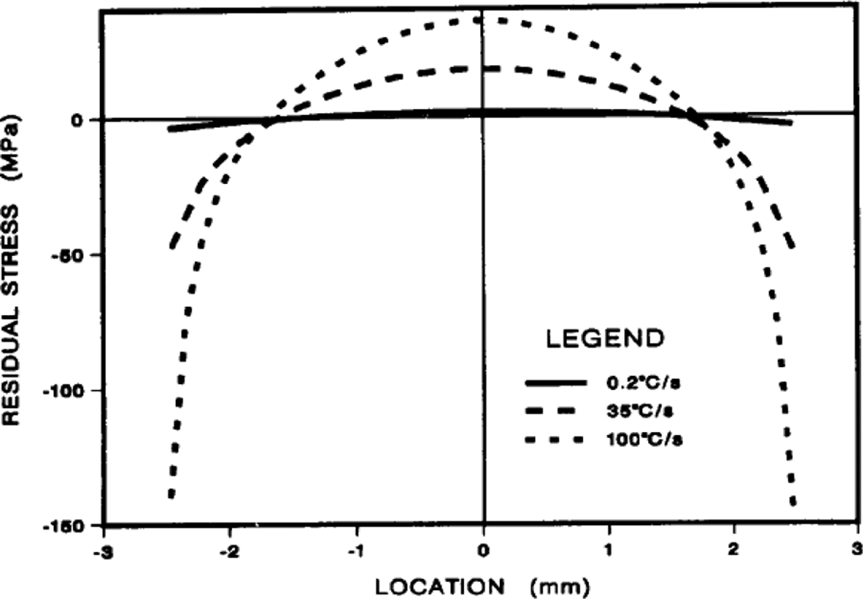
Influence of cooling rate on the transverse residual stress in a 40-ply APC-2 unidirectional laminate. 114 APC: aromatic polymer composite.
It is obvious that increasing the cooling rate increases the residual stress. Furthermore, the compressive stress at the surface of the laminate seems to be most sensitive to cooling rate. 114 Schlottermuller et al. 145 included a stress–strain submodel in their analysis for thermoplastic filament winding process.
Crystallization model
Depending on their thermal history, semi-crystalline polymers experience varying degrees of crystallinity 1,190 ranging from low percentages in quenching-like processing conditions having very high cooling rates, to more than 40% for processes involving very low cooling rates. 35 The lower the cooling rate, the larger the spherulite size and the higher the degree of molecular perfection which means higher crystallinity. 4,106,191 Figure 13 shows the variation of crystallinity versus cooling rate using the spherulite growth model. 87 The crystallinity of the matrix influences the mechanical properties such as stiffness and fracture toughness. 4,114 Higher crystallinity increases the resistance to some solvents, which is particularly important for aircraft applications. 74 However, optimum crystallization has a broad processing window, and working outside this window has small penalty. 190
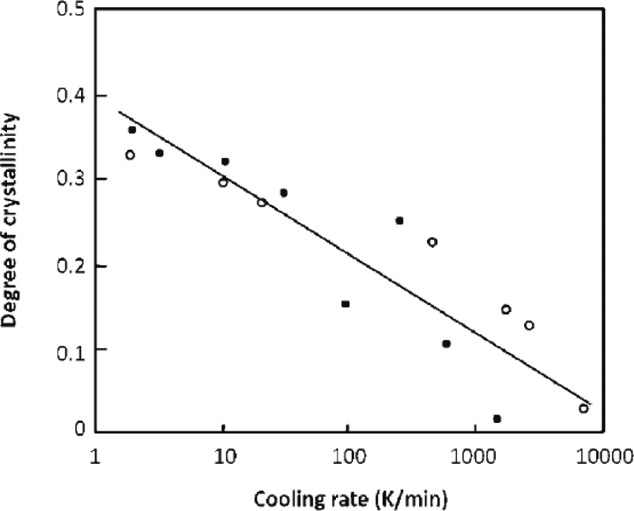
Variation of degree of crystallinity with cooling rate for PEEK and APC-2. 87
Gao and Kim studied the effect of cooling rate on the fiber–matrix interfacial bond strength, 191 the interlaminar fracture toughness, 192 and the impact damage performance 193 of CF/PEEK composites. They found that fast cooling resulted in higher damage resistance and damage tolerance in low-energy impact, whereas slow cooling resulted in high strength and modulus of the composite. Ray et al. 22 reported that high cooling rates can be advantageous for fracture toughness, due to increased polymer ductility. However, they questioned the applicability of such conclusion to the LATP process which involves cooling rates above 333°C s−1 as opposed to the range of 1–180°C min−1 studied by Gao and Kim. 192 Comer et al. 23 performed differential scanning calorimetry (DSC) analysis of LATP-manufactured specimens and obtained degree of crystallinity of just 17.6% versus 40% obtained for an autoclaved sample. They referred it to the nonlinearity of temperature distribution and rapid dropping of temperature, as well as the extremely high cooling rates, particularly while under the roller. They, then, suggested that high cooling rates down to Tg are desirable to avoid deconsolidation once pressure from the roller is removed. DSC scans on CF/PEEK laminates cooled down naturally at an average rate of 4°C min−1 showed that there was no crystallization peak which meant that maximum level of crystallization was attained. 27 Blundell et al., as reported by Mazumdar and Hoa, 79 investigated the effect of crystallinity over a wide range of cooling rates for APC-2 as well as the effect of annealing on crystallinity. Between 10°C min−1 and 600°C min−1, the crystallinity was in the range of 25–30%. For cooling rates of about 0.5°C min−1, higher crystallinity (in excess of 35%) could be achieved, whereas at a rate of about 2500°C min−1, the material was found to be amorphous. For annealing temperatures between 200°C and 300°C, the crystallinity attained a fairly steady value. Annealing at 200°C for 30 min gave a crystallinity of about 20%, whereas at the highest temperature of 320°C, crystallinity in excess of 35% was achieved.
Most of the crystallization models used in the literature are based on theoretical work by Avrami and Tobin. Although they were originally intended for isothermal crystallization, these models have been modified to describe nonisothermal crystallization. 62,111,118,120 The Tobin equation considers the effects of both heterogeneous and homogenous nucleation, whereas the Avrami equation considers the system to have completely melted without any residual nuclei. 76 The basic form of Avrami equation is given by 120

where X(t) is the relative volume fraction of crystallinity, t the crystallization time, k a crystallization rate constant, and n is Avrami exponent which depends on the nature of nucleation and growth geometry of the crystals. Ozawa 194 derived a nonisothermal kinetics of the process of nucleation and its growth by extending Avrami’s equation. He mentioned that the crystallization of polymers consists of two processes; the “primary” (Avrami) crystallization followed by the slow “secondary” (post-Avrami) crystallization. However, he described the kinetic analysis of the thermo-analytical data of the process by neglecting the secondary crystallization. Velisaris and Seferis 120 developed a crystallization kinetics model of PEEK involving two competing nucleation and growth processes based on Avrami equation. The model is capable of predicting isothermal as well as nonisothermal data with the same model constants. The complete expression of the nonisothermal crystallization kinetics model for a single crystallization process i (i = 1, 2) is
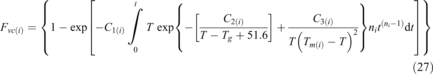
where Fvc is the normalized volume fraction crystallinity, C1 a constant coefficient of the temperature-dependent pre-exponential factor, C2 an empirical parameter associated with the temperature dependence of viscosity, C3 a parameter associated with the free enthalpy of nucleation, n is Avrami exponent, and T, Tg, and Tm are the temperature, glass transition temperature, and crystal melt temperature, respectively.
Lee and Springer 118 developed a 1-D crystallinity model based on Ozawa, 194 with the main goal of helping in the selection of the processing variables, rather than studying the detailed molecular processes and the morphologies involved in processing thermoplastics. Saliba et al. 111 incorporated three crystallization submodels into the heat transfer model for process modeling of complex shapes of thermoplastic composites. The first submodel is capable of predicting crystallinity rates only, and the second provides other morphological data but does not account for changes in the superstructure nucleation density, while the third accounts for the secondary crystallization. Mantell and Springer 119 used the crystallization model developed by Lee and Springer 118 to predict crystallinity levels in the tape placement process, whereas Nejhad et al., as reported by Sonmez and Hahn, 62 adopted the model of Velisaris and Seferis 120 and applied it to the filament winding process. Both these models do not include the effect of melt temperature on crystallization. Also, the constants depend on cooling rate, so they produce reliable results at high cooling rates for which experimental data are not available. These issues were taken care by the Sonmez and Hahn model 62 which adopted the model developed by Choe and Lee 195 for nonisothermal crystallization of PEEK to describe crystallization kinetics during the tape placement process. Although the model was developed for neat resin, it was assumed to be applicable for CF/PEEK composites supported by experimental data 118,120 that showed crystallization rates for APC-2 and neat PEEK resin are comparable. The model is based on Tobin equation for isothermal conditions. The resulting equations describe only the crystallization behavior, that is, when the temperature is between Tm and Tg, hence, to account for the crystal melting kinetics, they used the model developed by Maffezzoli et al. 121 in which the degree of melting is determined by integrating the rate of heat absorbed during the melting process as follows
where QT represents the total heat of fusion. The same approach was used by Tierney and Gillespie 56 ; however, they used the crystallization kinetics model of Velisaris and Seferis 120 for Tg < T < Tm and the melting kinetics model of Maffezzoli et al. 121 for T ≥ Tm, to predict crystal growth and melting under highly nonisothermal conditions usually experienced in in situ processing techniques such as ATP. The experimental results, using APC-2/PEEK, correlated well with the model predictions for heating rates in excess of 700°C s−1 and cooling rates up to 150°C s−1; hence, they suggested that the two models could be accurately used to predict crystallization growth and melting behavior of nonisothermal processes such as ATP. Phillips and Månson 196 proposed a crystallization kinetic model to describe the 3-D spherulite crystal growth. The model is based on modified Avrami equations to incorporate both heterogeneous and homogeneous nucleation and growth processes. Maffezzoli et al. 197 proposed a theoretical macrokinetic model for the crystallization of PPS matrix for high-performance composites starting with the Avrami equation. The model accounts for the induction time due to nucleation and is capable of predicting crystallization changes in isothermal and nonisothermal conditions, including cold and melt crystallization and quenching effects.
Process optimization
The processing window for new materials is determined by trial-and-error procedures. 20,22,50,60 Process modeling has many advantages; it can introduce savings by reducing the trial-and-error technique and enhance process optimization through the capability of studying the effects of process variables on produced parts. 2,111 A number of microstructural changes affect the properties of processed thermoplastic composites, for example, melting, degradation, crystallization, intimate contact, autohesion, residual strains, and void consolidation and growth. Selection of process parameters greatly affects these microstructural changes which in turn affect the mechanical properties of the finished parts. 60,79 Processing windows are developed based on certain quality requirements to provide bounds on the allowable values of the process controllable variables, 25 through the applicable process models as shown in Figure 14, as well as to find the optimum parameter settings which result in an in situ consolidating thermoplastic tape placement process competing the thermoset counterpart 19 in terms of maximizing bond strength and minimizing fabrication time. 25 The processing window of tape placement, which is highly temperature dependent, 71 is a narrow region between a lower bound, below of which is characterized by incomplete consolidation due to insufficient heating and diffusion resulting in high void content, and an upper bound, above of which is characterized by material degradation due to excessive temperature. 9,60,62,63,77,84,108,109,119
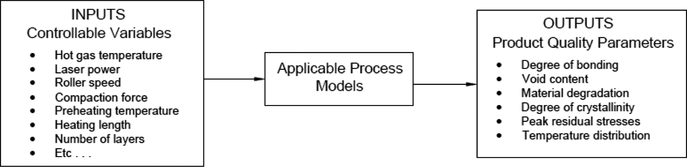
Optimization process: inputs and outputs of process models in ATP.
Several product quality parameters or responses were considered in the several parametric studies performed for the thermoplastic tape placement process. Bond strength, 16,19 –22,25,30,31,33,36,42,43,49,50,53,55,57 –61,63,65,69,70,73,75,77 –79,81,84,85,103,132 void content, 25,30,31,33,36 –38,42,43,53,57 –59,75,77,82,146 material degradation, 25,43,53,62,63,74,85 degree of crystallinity, 18,22,42,44,62,63,74,79,103 temperature distribution, 18,35,37,43,46,48,54,60,61,64,93,95,108 and residual stresses 18,61,77,79,80,85,95,103 were the most ones being used. A constraint characterizing the dimensional changes of the tow during compaction was also considered in terms of final tape width 82 as well as degree of compaction. 25 Furthermore, in some studies, roller force (usually a variable) was not varied; it was kept at the maximum value that won’t cause fiber-bed spread or resin starvation, and hence used as a constraint. 63,85 As for the controllable variables, they can be divided into three categories: setup related, material related, and process related. 36 Besides the heat input or amount of energy which has different forms depending on the type of heat source, the other two most investigated variables are the placement velocity/winding speed 16,18 –22,25,30,31,33,35 –38,42 –46,48 –50,53 –57,63 –65,68,70,77 –79,82 –85,92,132,146 and the compaction force. 16,18,20 –22,30,31,36 –38,42,43,48,55,57,58,61,63,65,70,77 –79,81 –83,146 For a process with laser as the heat source, several other parameters were reported such as laser power, 16,20,22,42,48,49,53,70,73 –78,84,144,165 laser angle, 19,22,48,49,74,108,165 laser spot bias toward the tape or substrate, 19,42,144,165 laser beam height, 19,165 laser beam alignment, 73,74,108 and so on. On the other hand, many parameters were being studied for a process involving a hot gas torch, such as hot gas flow volume, 36 –38,44,63,64,79,146 hot gas temperature, 25,33,43,44,54,57 –60,64,65,81,83,85 and torch distance. 30,31,44,57,58 Many other variables were being reported or investigated, such as preheating temperature, 25,33,43,54,57 –59,63,85,95 heating length, 36,54,62,63,85,95 heated length ratio, 62,63,85,95 tool temperature, 18,22,36,38,42,53,55,57,58,62,146 roller temperature, 22,45,53,81 roller diameter, 18,36,62,63 repetitive passes, 37,53 incoming tape quality, 36,38,42,146 and number of layers 36,44,45,57,58,61,63,159 among others. Specific to the case with IR heating, the parameters of heat intensity, 35,45,46,92,93 heater length, 35,45,46,92 and tape thickness 54 were investigated, whereas in the case of ultrasonic heating, the parameters include vibration frequency and amplitude 21,157 as well as welding force, vibration time, and solidification time. 157
To perform the optimization studies and/or to solve the thermal models, many authors used simulations supported by experiments, 16,19,30,31,37,38,48,49,53,57,64,65,69,72,80,97,107,138,146 whereas others opted to perform only simulations 1,18,25,33,35,44,46,47,54,58,62,63,68,85,93,170 or depend solely on experimental work. 20,22,42,50,55,59,70,73 –75,77 –79,81,83,84,165 Design of experiment and/or Taguchi method were used by some authors to analyze the results of their optimization studies. 20,21,48,50,70,78,80,82,145
Some of the findings of the optimization studies related to LATP processes include as follows: The laser power and placement velocity were found to have the most influence, whereas compaction force had no significant effects.
16,20,48,70,78
The bond strength was found to increase with increasing laser power up to an optimum value and then decreased due to matrix degradation,
75,78
whereas tape speed had a nonlinear effect.
78
A slight misalignment of the laser beam could lead to a good reduction in shear strength, and a laser beam biased toward the substrate had a lower shear strength compared to a one biased toward the incoming tape.
73
An excellent bond could be obtained at high placement velocities combined with low laser power provided that the laser is predominantly directed toward the tape.
49
Improved consolidation and enhanced quality can be obtained by the use of a preheater
75,108
or a wider laser beam.
108
Also, the use of preheating or post-annealing is recommended when higher degrees of crystallinity are required.
96
An unheated nonmetallic tool provided the best peel force and void content (1%) for the LATP process; however, due to the rapid cooling rates, the level of crystallinity was low (approximately 20%).
42
The most efficient modifications to improve the degree of bonding in the laminates are (1) perform an additional compaction pass without adding material after each pass with material, (2) preheat the tool, and (3) modify the laser position so that the temperature drops before the roller is reduced.
53
As for the ATP process with hot gas torch, some of the findings include as follows: A relatively large processing window exists.
81
It gets narrower when the main heater torch temperature is increased. Furthermore, the two common objectives of the processing window are not necessarily achieved together; time-optimal solutions don’t lead to maximum strength and conversely, strength-optimal solutions don’t lead to minimum fabrication times.
25
Compared to main heater temperature, preheater torch temperature had negligible influence on maximizing strength or minimizing production time.
25,33
Preheating improves consolidation when it is done for the substrate
54,62,63
but not for the incoming tape or the roller.
63
The gas temperature is the key variable in the process, the compaction force has no significant effect on ILSS values, and that for each optimum gas temperature, there exists an optimum roller temperature.
81
Degree of bonding improved as a result of increasing the heat input from the torches; however, a higher final void content was obtained when the tows were left to cool down naturally beyond the exit of the consolidation roller. Hence, forced cooling of the tows beyond the consolidation zone may be necessary to obtain parts with low void content.
33
A large heat input doesn’t always guarantee maximum consolidation. Higher process velocity can reduce the production time at the cost of structure quality.
37
Low processing speeds must be accompanied by appropriately decreased gas nozzle temperatures to avoid material degradation, and increased roller speeds must be accompanied by appropriately increased gas nozzle temperatures to aid in the consolidation process.
60
Using lower speeds during placement of the last layer and the first few layers was suggested to improve bonding.
63
Speed can be increased after several layers as these layers act as insulation which results in the desired high temperatures and uniform temperature distributions. Furthermore, starting with a low consolidation force and then increasing it while more layers being deposited was recommended due to the developed interlaminar stresses being higher as the beginning.
18
Increasing tool temperature resulted in better lap-shear strength and fracture toughness properties.
55
For a process with hot air gun, it was found that consolidation can be improved by installing a thermal insulation ring on the metal winding mandrel, as well as preheating the mandrel.
136
An optimized placement equipment is difficult to define, and an optimization is possible only when the final component to be produced is known. For example, if a high degree of bonding together with low void content is required using a setup that has only one compaction roller, then a tape with lowest initial void content, a high tool temperature, intense heating of incoming tape and substrate, and low placement velocity should be used.
36
Mechanical and physical characterization
Mechanical characterization
In the course of evaluating the bonding in thermoplastic composites manufacturing, several test methods were used. As a fast qualitative technique, the consolidation of rings was evaluated by the sound the ring made when dropped on a hard surface. 83 The SBS strength test based on ASTM D2344 standard is one of the most common tests used to measure the bonding strength in terms of ILSS. 20,21,31,39,41,55,59,65,69,70,75,78,81,103,109,136,191 The closely related test based on DIN EN 2563 38,132,146 or BS EN 2563 23,127,128 was also used. Another very common test for assessing bond strength is the double cantilever beam (DCB) test which is based on the ASTM D5528 standard and is often used to evaluate mode I interlaminar fracture toughness. 15,21,22,42,55,77 –79,107,109,127,128,192,198 These SBS and DCB test methods require multilayered samples to be manufactured and are time consuming. Alternatives to them include rapid screening tests such as the lap shear tests and the wedge peel test, which can be used to characterize the strength of a single interface. 17,130 Different lap shear tests were used, such as ASTM D5868 16,17,55,169 and ASTM D3165. 4,65,137,177 Lap shear tests have their own disadvantages; the complex failure modes and stress concentration effects make it difficult to interpret the results, and it is not straightforward to evaluate the weld consistency along the weld length. 50 Wedge peel test to measure mode I interply bond strength was used. 23,67,127,132,146 Although still a comparative technique, however, wedge peel test suffers from certain challenges such as the high friction between the wedge and the tap and the difficulty in relating the measured fracture toughness to the constituent material properties. Hence, as an alternative, mandrel peel test was used to quantify the interfacial fracture toughness as a measure for the weld strength. 49 –52 The test methods, SBS and interlaminar shear device (ISD) as a technique to evaluate part quality and determine the value of the shear strength, were compared. 72 The ISD method includes a mode II loading so that the ILSS can be approximately determined in a direct manner. It was found that ISD gave better and more reliable measure of the composite strength, and hence was used in another work. 73 Gao and Kim 191 studied the effect of cooling rate on the fiber–matrix interface adhesion for a CF/PEEK composite based on SBS, fiber fragmentation, and fiber pullout tests. The SBS test was used to measure ILSS, whereas the other two tests were used to measure the interfacial shear strength (IFSS) of the fiber–matrix interface. The blocking force test based on ASTM D1893-67 is usually used to measure the adhesive strength of polymers; however, it was used 109 to characterize the bonding quality of four-ply. C-ring tests were performed to evaluate failure stress, strain, and deflection of C-rings at room temperature. 94 Several other mechanical tests were carried out depending on the requirement of the respective research work, for example, tension test (ASTM D3039), compression test (ASTM D3410), and shear test (ASTM D3518) 27 ; unnotched pendulum impact test (ASTM D3420) to measure impact toughness 21 ; a three-point bending test (ASTM D7264) for determining flexural modulus and strength 26 ; a flexural test based on BS EN 2562 23,127,128 ; OHC test based on ASTM D6484 23,127,140,141 ; and open-hole tension (OHT) test. 141 Consolidation and bond quality were also estimated using the nondestructive ultrasonic testing. 97,116
Physical characterization
Several physical tests were performed for mainly characterizing the fabricated parts in terms of morphology, voids, and defects. DSC is very common. 22,27,48,51,56,67,77,79,101,107,109,113,118,120,124,127,128,140,196,197 It is a thermal technique in which transitions in materials are captured and measured in terms of temperatures and heat flows as a function of time and temperature in a controlled atmosphere (usually nitrogen). For thermoplastics, it is usually used to measure glass transition, crystallization, and melting temperatures Tm s. It is the most common method to determine the level of crystallinity of semi-crystalline thermoplastic composites. However, there are other techniques that can be used to measure crystallinity such as IR spectroscopy, optical microscopy, small angle X-ray scattering and electron microscopy, 56 wide angle X-ray scattering, 56,191 and density method. 191 As compared to DSC, modulated DSC was found to be a more appropriate method as it accounts for exothermic events during melting and endothermic events during cold-crystallization. 74 On the other hand, dynamic mechanical analysis (DMA) was used to measure T g and/or storage modulus 69,107,127,183 as well as damping behavior. 22,127 Thermogravimetric analysis (TGA) was used to measure the thermal degradation of PEEK in terms of weight loss. 185,186,199 Thermal degradation was monitored through variety of other techniques such as solution viscometry, ultraviolet–visible spectroscopy, and Fourier transform infrared (FTIR) spectroscopy. 200 Density gradient technique (DGT) was used to determine crystallization kinetics of PEEK 120 ; 2-D microscopy and/or 3-D X-ray tomography followed by image capture and analysis were used in several experimental works for voids and defects analysis. 23,37,38,53,55,59,73,109,127,128,133,176,183,184 Furthermore, surface texture was analyzed by white light interferometry (WLI) 169 and scanning electron microscopy (SEM). 22,39,78,94,169 A nano-indentation technique for determining matrix modulus and hardness was also reported. 22
Quality assurance
A nonoptimized tow placement process could result in several manufacturing defects such poor consolidation and poor interfacial bonding. These, in turn, could lead to interlaminar strength degradation, introduction of interlaminar and intralaminar porosity, excessive polymer degradation, and nonoptimum crystallinity levels. 24 Other quality issues may include high levels of internal stress and warpage and changing fiber architectures. 4 Furthermore, there are another set of defects, in AFP process, related to the geometry of the process. Such defects include gaps/overlaps, fiber bridging, and wrinkles. These defects usually can’t be eliminated but can be adjusted through part design. 34 One more category of defects includes missing tows, twisted tows, foreign bodies, and tow defects. 201 Nowadays, most of the inspection and repair processes are done manually and account for about 30% of the manufacturing time, which significantly reduces the productivity of the process. 34 Cost reductions can be achieved through the inclusion of online nondestructive inspection into the overall process. 202 Chen et al. 34 listed several off-line and online inspection systems that have been used to reduce the time required for defect inspection and improve the process efficiency such as laser projector, image processing, IR-based sensors, and laser triangulation technique. Besides thermo-physical analysis and destructive tests, nondestructive evaluation tools are highly necessary for appropriate control of the two placement processes as being able to detect and characterize possible structural flaws without altering the test piece and can provide online health monitoring during manufacturing. 24 Ultrasonic surface waves are particularly suited for the detection and characterization of surface and substrate defects as they propagate on the top-most layers of the test material and experience less attenuation than that associated with bulk longitudinal or shear waves. Hence, surface waves are suitable candidates for online process control of the thermoplastic tow placement with in situ consolidation. 24 Heider et al. 148 investigated a neural network-based control system for the automated thermoplastic tow placement process. It incorporates an advanced controller that predicts desired part quality at minimal cost. The control system combines a neural network-based model, numerical and neural network optimization, and an IR thermal imaging camera to sense the temperature profile on the part surface. One of the future activities directed toward achieving the goal of automated fabrication of high-performance composites is to develop sensors for online part quality information and in situ defect repair. 130
Conclusion
ATP is a promising process to manufacture high-quality thermoplastic composite components for aerospace industry as well as automotive and other sectors. The process has gone through several developments and enhancements supported by the high-quality thermoplastic prepreg tows and tapes being currently produced with lower void contents, by the introduction of highly efficient and highly controllable heat sources such as fiber and diode lasers, the advanced equipment to perform detailed experimental investigations with much high accuracies, and the fast computers that allow performing complicated modeling and simulations in a much shorter time. However, still, as of today, more work is required before having the process completely commercialized. Improving the consolidation to match or maybe exceed the autoclaved levels as well as increasing the throughput are two of the main challenges to overcome in order to achieve this.
Footnotes
Acknowledgements
The authors wish to thank the Natural Science and Engineering Research Council of Canada.
Declaration of Conflicting Interests
The author(s) declared no potential conflicts of interest with respect to the research, authorship, and/or publication of this article.
Funding
The author(s) disclosed receipt of the following financial support for the research, authorship, and/or publication of this article: This work was financially supported by Natural Science and Engineering Research Council of Canada.