
Abstract
Long fiber thermoplastic (LFT) composites have gained significant attention in various industries due to their desirable properties, including ease of processing, recyclability, superior strength, and corrosion resistance. Glass fiber (GF) is commonly used as a reinforcing material in LFT composites, given its low cost and excellent mechanical properties. However, there are challenges associated with the existing manufacturing processes, such as fiber attrition and limitations in achieving anisotropic properties. In this study, the overmolding of glass fiber-reinforced polyphenylene sulfide long fiber thermoplastic (G-LFT) and unidirectional continuous carbon fiber/polyphenylene sulfide tape (CF-Tape) using an Automated Tape Placement (ATP) robotic system has been investigated. The aim is to explore the potential of ATP for improving the mechanical properties of LFT composites. The results reveal that the overmolding process using CF-Tape on G-LFT leads to significant enhancements in mechanical performance. A 129% increase in tensile strength and a 192% improvement in flexural strength were observed compared to the G-LFT baseline. The bond strength at the interface was evaluated through flatwise tensile testing, which resulted in partial failure within the CF-Tape and a measured bond strength of 7.52 MPa ± 0.34. Thermogravimetric analysis (TGA) and differential scanning calorimeter (DSC) were conducted to analyze the thermal behavior of the parts. The crystallinity was measured using DSC data, and a value of 33.4% was obtained. Low-velocity impact testing has been conducted to understand the dynamic behavior of G-LFT and G-LFT/CF-Tape. The impact energy absorbed was found to be similar in both cases. A numerical model was used to reduce the number of experiments. It was found that the flexural strength would improved by 60% by adding five layers of CF-Tape. In summary, this research contributes to expanding the knowledge of overmolding techniques and highlights the potential of ATP-based overmolding for for enhancing the localized strength and easily applied to intricate geometries.
Keywords
Introduction
Long fiber thermoplastic (LFT) composites are a popular choice in the automotive and transportation sector due to their ease of processing, recyclability, superior specific modulus and strength, excellent impact, corrosion resistance, and long shelf life.
1
Various thermoplastic polymers ranging from commodity (e.g.: polypropylene (PP), high-density polyethylene (HDPE), etc.) to high-performance engineering (e.g.: polyamide (PA), polyphenylene sulfide (PPS), polyether ether ketone (PEEK) etc.) have been used as matrices in LFTs.2,3 As a result, LFTs have become one of the most advanced lightweight engineering materials, and their demand is continuously increasing in various sectors such as automotive, aerospace, electrical, etc.
4
Glass fiber (GF) is frequently employed as reinforcing material in LFTs because of low-cost and superior mechanical properties.
5
LFT composite parts are manufactured via injection molding (IM) or extrusion compression molding (ECM). The IM process provides higher mechanical properties in the direction of the flow
6
; However, it results in higher fiber attrition due to the shear stresses induced in the compounding screw. ECM composites provide pseudo-isotropic properties in the finished part with more fiber length retention as compared to IM.
7
However, both IM and ECM parts are limited by the aspect ratio of the discontinuous fiber.8–10 One approach to enhance the mechanical performance of disconitnuouis fiber i.e. LFTs is overmolding.11,12 The purpose of composite overmolding is to integrate advantages and reduce shortcomings of a 100% discontinuous composite, like LFT. Alwekar et al.
7
studied the overmolding of glass/polypropylene LFT and unidirectional continuous glass-polypropylene tape. The overmolded panel was manufactured by compression molding . The authors reported 119–142% and 60–70% increase in flexure strength and modulus, respectively. However, they observed an out-of-plane warpage in the finished consolidated panel. Heer et al,
13
studied the mechanical properties of overmolded GF/polyamide 6 (PA6) long fiber thermoplastic-direct (LFT-D) and glass mat thermoplastic (GMT). The authors compared the properties of the overmolded sample with constituents such as LFT-D and GMT and observed that the properties ranked as follows- GMT > overmolded > LFT-D. Therefore, based on the particular application, the properties of the overmolded part could be tailored according to the placement of the constituent. However, the process consists of some drawbacks such as out-of-plane warpage that could occurr in the finished part. Gan et al.
14
studied the absorption properties of grid-stiffened thermoplastic composites under transverse loading. Commingled unidirectional Twintex® E-glass-PP and commingled woven Twintex® E-glass-PP were used to construct the ribs and skin, respectively. The commingled fibers were arranged in grooves to create the ribs, with the skin made up of commingled woven fabric and integrally bonded to the ribs. This approach provided uniform fiber distribution and fibers oriented in the direction of the ribs. However, despite its numerous benefits, this technique is highly time-consuming and not cost-effective. Lee et al.
15
developed a rib-stiffened composite side impact beam (SIB) by co-molding LFT ribs with woven glass fabric prepregs. The authors conducted tension and compression tests. The results showed that the specific strength of the composite SIB was 130% and 10% higher than steel SIB in tension and compression, respectively. It was reported that hybrid composites could be a good replacement as compared to steel for SIB. This study consists of fabricating and analyzing the overmolded LFT panel, the overmolding conducted with automated tape placement (ATP). In recent years, ATP has become a main stream composite manufacturing technique with significant increase in demand from 6% in 1990 to 35% by 2020.
16
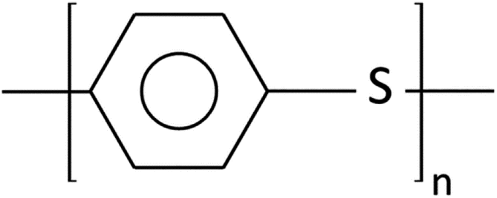
ATP in situ thermoplastic composites has witnessed an interest from various industries such aerospace, oil and gas, due to elimination of secondary post-curing process such as autoclave molding, resulting in cost and energy effectiveness.17–20 More details about ATP can be found in Refs..21–29. In this work, glass fiber reinforced polyphenylene sulfide long fiber thermoplastic (G-LFT) and unidirectional continuous carbon fiber/polyphenylene sulfide tape (CF-Tape) was used. PPS is an engineering thermoplastic polymer known for its high temperature resistance, featuring a molecular structure composed of alternating aromatic rings and sulfur atoms as shown Figure 1. PPS boasts a noteworthy array of properties, including thermal stability, chemical resistance, flame resistance, wear resistance, processability, low coefficient of thermal expansion, and impressive mechanical characteristics. The semi-crystalline nature of PPS provides benefits such as the capability to be utilized above the glass transition temperature without compromising modulus and resistance to creep deformation.
30
Therefore, PPS finds application in the automotive industry, particularly in situations requiring elevated temperatures.31,32 To the best of the authors’ knowledge, no research has been conducted on the overmolding of CF-Tape and G-LFT processed with the ATP robotic system. Previous studies have explored hybrid overmolding using injection or compression molding, mostly involving pre-consolidated laminates or short-fiber substrates. However, the overmolding of in situ consolidated continuous CF-Tape tapes onto long glass fiber-reinforced thermoplastics using ATP has not been reported. The interface bonding behavior, thermal compatibility, and mechanical performance under ATP processing conditions remain largely unaddressed. In this study, an overmolded panel of G-LFT and CF-Tape was manufactured. A morphological study was conducted to examine the bonding at the LFT-Tape interface. The interface mechanism was further evaluated mechanically using a flat-wise tensile test. A number of mechanical tests such as tensile (ASTM D3039), flexural (ASTM D790), and short beam shear (ASTM D2344) were performed in order to understand the effect of overmolding. Low velocity impact (ASTM D7136) testing was also carried out to analyze the effect of energy absorption after CF-Tape overmolding. A numerical analysis was implied to minimize experimental iterations by evaluating the effect of CF-tape layer quantity and orientation on localized strength, using a validated model of the three-point bending test. Chemical structure of polyphonelic sulfide (PPS)
32
.
Materials and methods
Materials
A 12.7 mm (½-inch) 60% weight (wt.) GF reinforced PPS LFT pellets (PPS-GF60, LFT Celstran®) were procured from Celanese (Ticona/Celanese, Winona, MN, USA). A 12.7 mm (½- inch) wide unidirectional CF-tape (AS4/PPS) tape, 66% wt. CF and with an approximate thickness of 0.16 mm was provided by Cytec Engineered materials, now, Solvay S.A Inc. (Alpharetta, GA, USA). ATP KAWASAKI ZZX130 L 6-axis robot, located at the IACMI-Composites Institute, Knoxville was used for the fabrication of the overmolding panel using the hot gas torch head (HGT) developed by Automated Dynamics in 2013, now, Trelleborg Group, Sweden.
Processing
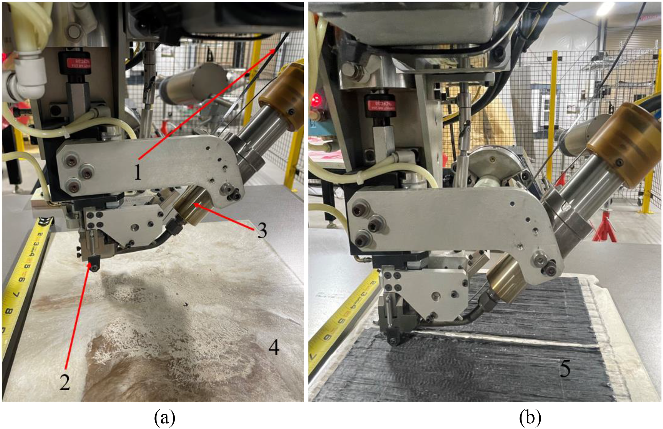
The process to obtain an overmolded panel was divided into two steps. (a) The first step was the manufacturing of the substrate LFT plate(s). G-LFT pellets and CF-Tape were dried at 80°C for 8 hours before any processing. Dried G-LFT pellets were used in the ECM process to manufacture the panels. ECM process involved two operations extrusion and compression molding. In the first operation, the pellets were fed into a single screw extruder (B-30 IMPCO Plasticator) at a rate of 0.454 g/min (1lb/min). The extruder consists of four heating zones to melt the polymer which were kept at 295°C, 300°C, 305°C, and the nozzle temperature at 310°C. The hot, molten charge 38 cm × 7.6 cm approximately (15 × 3 inch) obtained from the plasticator was transferred to the fast-acting Wabash (Model DA150-36-BCX) hydraulic compression press. A 280 mm × 280 mm × 3.2 mm (11 × 11 × 0.125 inch) consolidated panel was fabricated under 2.89 MPa (420 psi) pressure with 60-s dwell time as shown Figure 2. (b) The second step involved the manufacturing an overmolding panel using the ATP process. The G-LFT panel was mounted on an aluminum flat mandrel as shown in Figure 3(a). An ATP system includes a coordinated spindle, a stainless-steel compaction roller (placement head), a tape dispensing system, and HGT as a heat source. The tape was fed into the roller and heated using HGT. The temperature for HGT was kept at 840°C (temperature of the torch and not at the contact place with the mandrel). The nip temperature was noted to be approximately 290°C at the contact point between the tape and G-LFT panel substrate. The temperature was monitored using a Teledyne FLIR A700-EST IR camera. One layer of the CF-Tape was laid down on the substrate as shown in Figure 3(b) and bonded with the combination of heat and pressure 63.5 Kg (140 lb) applied through a compaction roller of 12.7 mm (½- inch) diameter. No visible warpage or residual deformation was observed in the overmolded parts after ATP processing. The parts remained flat after cooling and maintained dimensional stability. Visual inspection confirmed that the flatness of the specimens was within the tolerances specified in ASTM D790 and ASTM D3039, ensuring their suitability for subsequent mechanical testing. During the overmolding process, the asperities of the substrate and the tape were flatten during consolidation due to the pressure applied by the compaction roller and the temperature generated by the HGT, leading to “intimate contact”. Once this phenomenon occurs, the presence of interlaminar voids diminishes, facilitating molecular chain interdiffusion between G-LFT and CF-Tape, thereby establishing a robust bond at the interface.33,34 Schematic of the extrusion compression molding process for LFT composites. G-LFT are melted and conveyed through a screw extruder to form a charge, which is then transferred into a mold cavity and compressed into the final part shape. Illustration of the ATP robot: (1) CF-Tape 12.7 mm (½- inch), (2) The compaction roller, (3) The HGT, (4) The G-LFT substrate (5) The overmolded part. (a) The G-LFT substrate before overmolding. (b) The CF-Tape will pass through a guide slot, the tape will be heated with the HGT, and in situ consolidated on the substrate with a load of 64.5 Kg (140 lb) applied by the compaction roller.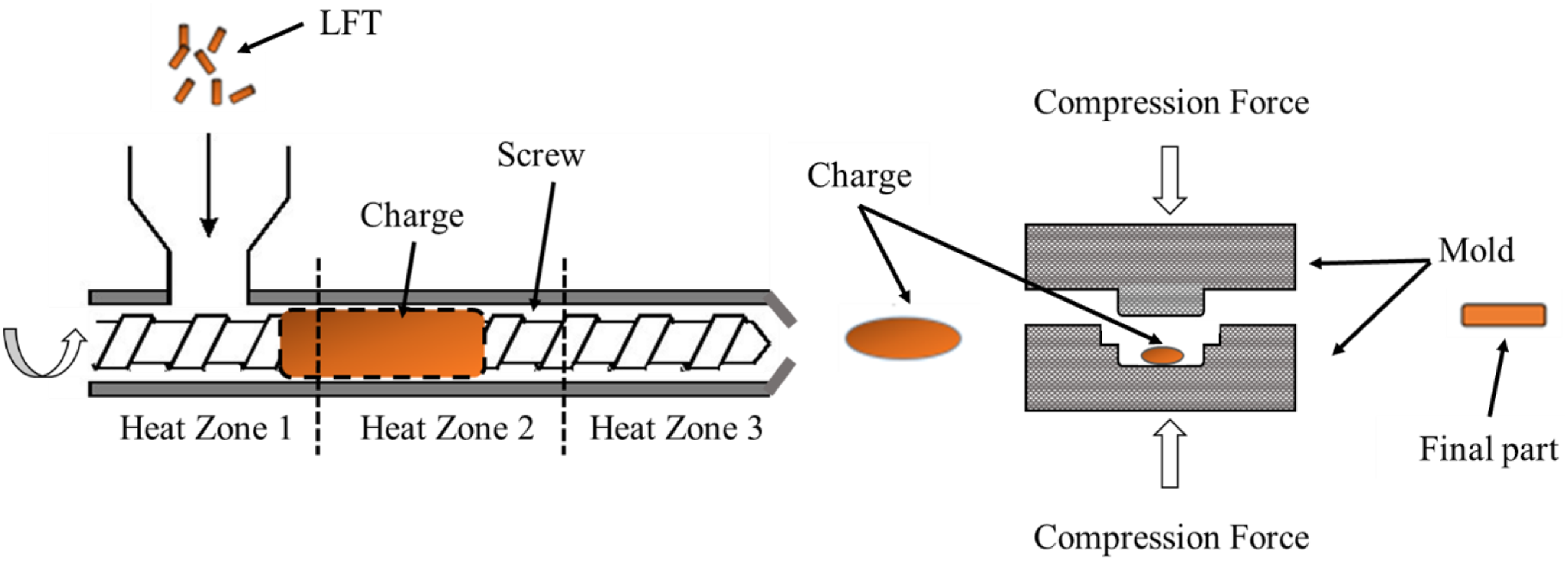
Testing and analysis
Three-point bending or flexural test
Flexural specimens were cut from the overmolded plaques using an OMAX Waterjet 2026 system to ensure precision and prevent edge defects or thermal damage. Samples were extracted along the longitudinal direction of the CF-Tape to align with the fiber orientation. Testing was performed using a universal testing machine (Test Resources, Model 313 series, Minneapolis, MN) equipped with a 50 kN load cell, in accordance with ASTM D790. The three-point bending configuration was arranged such the CF-Tape side was under tensile loading, as CF performed better in tensile than compression35,36 while G-LFT section was under compression loading as shown in Figure 4. Five specimens from each plaque (i.e., LFT and overmolded) were tested at 1.59 mm/min loading rate and average flexural properties were reported. The fractured surface of the flexural test specimen and the morphology of the delamination between CF-Tape and G-LFT was examined using a Zeiss EVO 25 scanning electron microscopy (SEM). Flexural setup for the overmolded specimen, the tape was from the bottom side, as CF performed in tensile better than compression.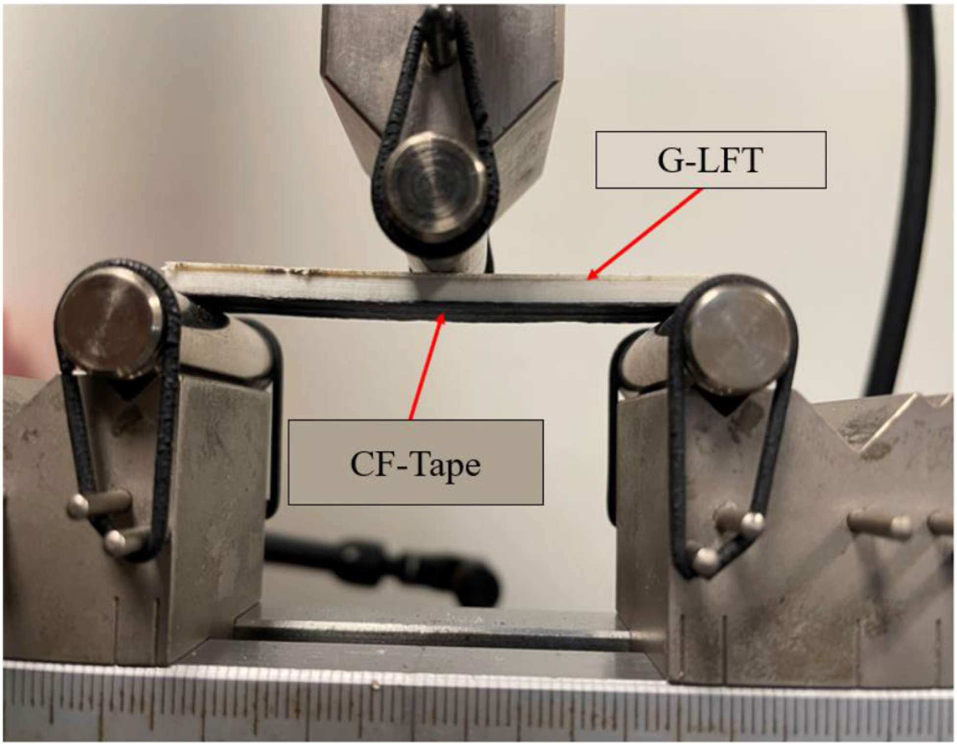
Thermal analysis
Thermogravimetric analysis (TGA) was conducted under a nitrogen atmosphere to prevent oxidative effects and to accurately evaluate the thermal stability and degradation behavior, of both G-LFT and G-LFT/CF-Tape composites. TGA Q50 was used at a heating rate of 15°C/min starting from room temperature to 800°C. Differential scanning calorimetry (DSC) utilized to portray the melting behavior of the G-LFT substrate and the overmolded samples. DSC sample was sectioned through the thickness to include the interface region, comprising both the CF-Tape and a portion of the underlying G-LFT substrate. DSC was performed using DSC Q2000 setup by applying heating and cooling. Samples were dried 24 hours at 80°C prior testing, then heated from room temperature to 400°C and cooled down to 20° in presence of liquid nitrogen (50.0 L/min) with a rate of 20°C/min.
Flatwise (through-thickness) tensile strength
A flatwise tensile test was performed to understand the bonding characteristic of the overmolded tape on the G-LFT panel. According to ASTM D7291 standard, through-thickness testing specimens were prepared with an average diameter of 25.4 mm and 4 mm thickness. Two aluminum cylinders were attached to the specimen using J-B WeldTM epoxy. A square mesh pattern was created on the aluminum surface (see Figure 5) to increase the surface area for proper bonding. Prior to the testing, the specimen was kept under pressure (50 psi) for 24 hours for the complete curing of epoxy. Test resources frame (50 kN load cell) was used to pull the samples at 0.1 mm/min loading rate. (a) Sample preparation of the overmolded part and surface modification of the aluminum end tabs. Aluminum tabs were modified to achieve a failure on the interface and not in the glue part. (b) Glue placed on the end tabs and specimens were mounted for out of plane tension test.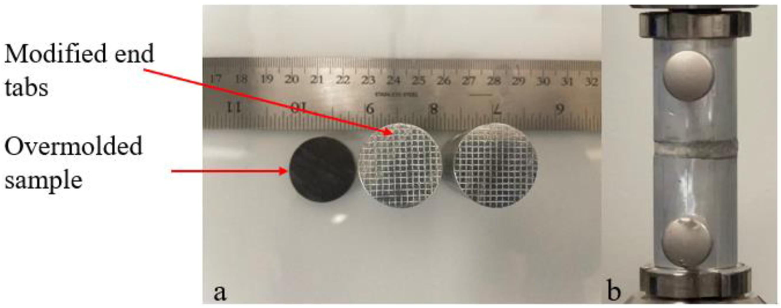
Tensile (in-plane) test
A set of five (5) specimens was prepared for tensile testing according to ASTM D3039. The average width and thickness of the overmolded sample was 254 mm × 25.4 mm (Length x Width). All specimens were tapped using GEEX 1871224N glass epoxy (Accurate PLASTICS) and superglue (Gorilla). The test was performed on the 50 kN load cell test resource frame and samples were pulled at 2 mm/ min loading rate. Strain was monitored using an axial extensometer, Model 3542 Technology Corp, Jackson WY 83001 USA.
Drop-tower (low velocity) impact test
The low velocity impact (LVI) tests were conducted using the Instron CEAST 9340 drop tower. A set of 5 specimens with 101.6 mm × 152.4 mm (4 × 6 inch) dimensions were prepared according to ASTM D7136. In this test, a hemispherical tup of 16 mm (0.63 inch) diameter and 3.22 kg (7 lbs) weight was used. A tup was dropped on a specimen from 1080 mm (42.5 inch) height with 4.6 m/s velocity, generating 34 J kinetic energy.
Results and discussion
Interface bonding
Figure 6(a) shows the optical microscopy (OM) image of the overmolded sample. OM image analysis was conducted to evaluate the weld line behavior and the effect of ATP overmolding on the G-LFT surface. Figure 6(b) reveals no porosity or defects in the substrate G-LFT surface or at the interface. However, matrix deformation has been noticed at the interface, attributed to the heat applied by the HGT during the ATP overmolding. This deformation suggests localized melting, which promotes molecular interdiffusion between the G-LFT and CF-Tape, enhancing interfacial bonding. To further understand the bond characteristics, interlaminar shear strength (ILSS) testing was conducted in accordance with ASTM D2344. The ILSS specimens were tested at a constant rate of 1 mm/min. Figure 6(b) shows the OM image of the failed sample. A strong bond at the interface was indicated by the limited delamination between the two surfaces and the presence of G-LFT matrix residue on the CF-Tape surface, suggesting cohesive failure. Additionally, embedded resin and fiber imprints were observed, pointing to the development of mechanical interlocking. The ILSS increased from 18 MPa for the G-LFT to 24 MPa after ATP overmolding, representing a 33% improvement, supporting the effectiveness of the bond formed at the interface. (a) OM image showing the bonding adhesion on the interface after the overmolding process between the G-LFT and the CF-Tape. (b) A slight delamination has been noticed on the interface of an ILSS tested sample, the GF/PPS attached on the failed tape evidence the strong bonding on the interface.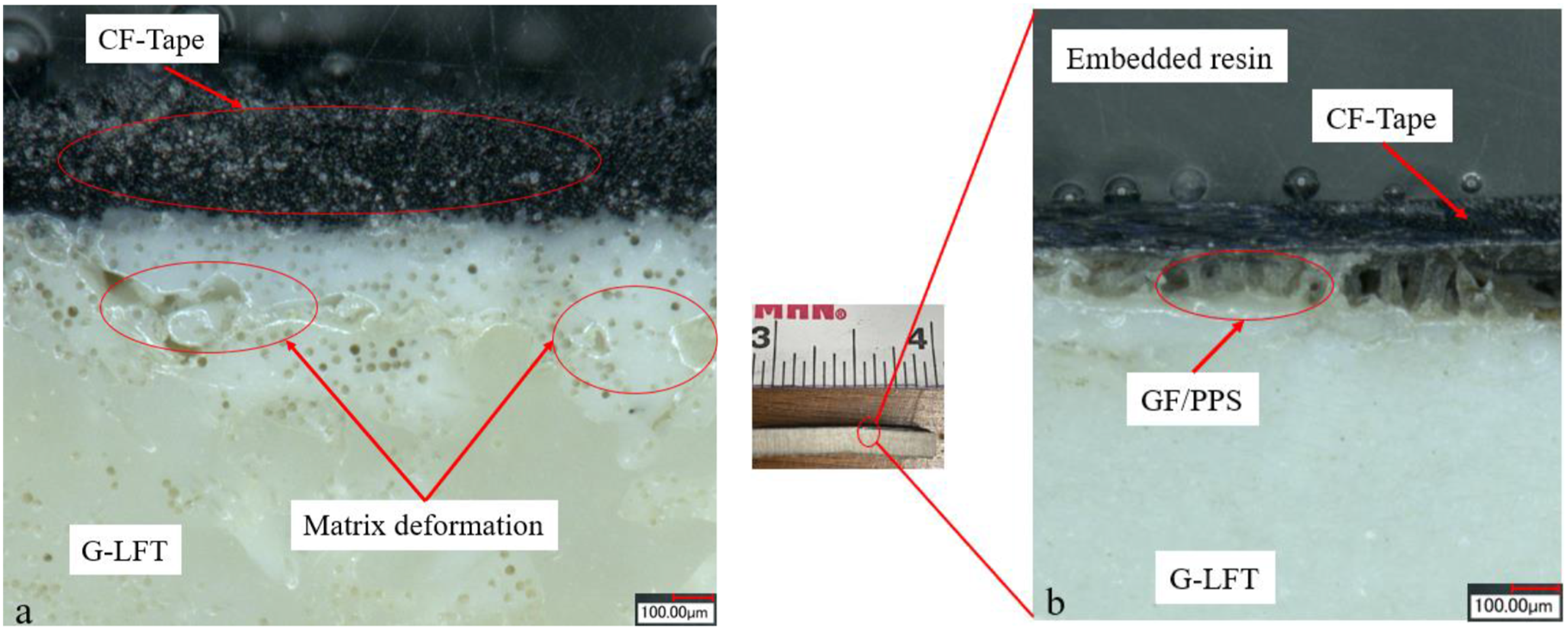
Thermal analysis
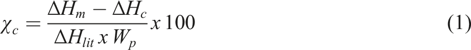
Figure 7 show the DSC and TGA results of G-LFT and G-LFT/CF-Tape, respectively. The twenty (20) samples were dried at 80°C for 8 hours in the oven to avoid moisture effect. The heat-cool cycle was applied for the DSC. It can be noticed from the heating cycle that G-LFT and G-LFT/CF-Tape had a similar glass transition Tg and melting point in the range of 125–130°C and 280–285°C respectively. Melting point determines the lower limit for processing temperature. It could be observed from the cooling cycle that the recrystallization of the G-LFT and the overmolded sample started at 245°C. The degree of crystallinity (a) DSC of G-LFT and G-LFT/CF-Tape, showing the melting point (285°C) and the crystallization point (225°C), (b) TGA analysis of G-LFT and G-LFT/CF-Tape showing that the degradation temperature of the composites started at 425°C.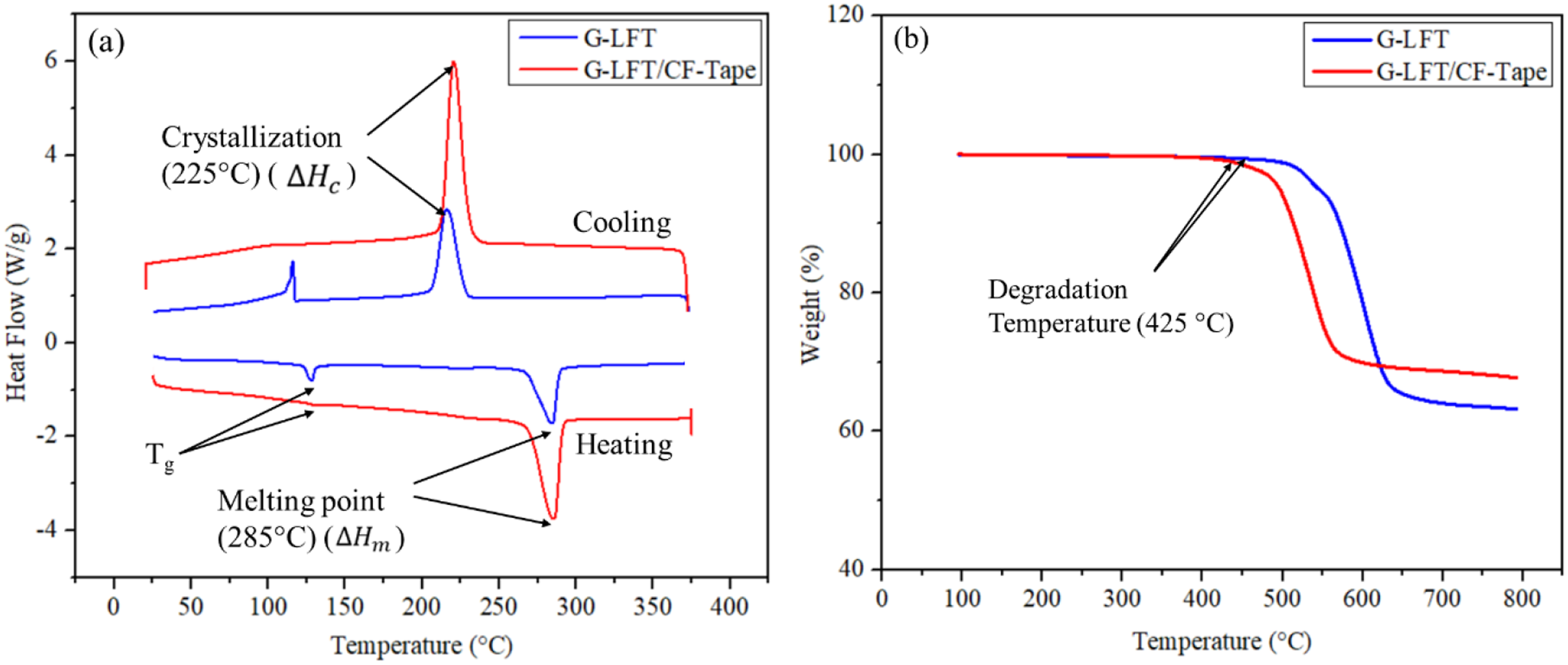
Flexural testing
A three-point bending test was conducted to assess the performance of continuous CF-Tape on the G-LFT plaque. Figure 8(a) presents the properties derived from the flexure test results. Figure 8(a) displays the flexural strength and modulus, while Figure 8(b) illustrates the load versus displacement curve. Notably, a single layer of 0.15 mm unidirectional CF-Tape was overmolded onto the G-LFT surface. The flexural strength and modulus of the overmolded G-LFT increased from 99 MPa to 290 MPa (a 192% increase) and from 5.09 GPa to 11.04 GPa (a 120% increase), respectively. These results demonstrate that the addition of CF-Tape to the G-LFT plaque enhances its bending resistance. Additionally, both samples exhibited a brittle type of failure, as observed in Figure 8(b). The reduced deformability observed in the composite is primarily attributed to the high glass fiber content (>60 wt%), which significantly increases stiffness and introduces stress concentrations at the fiber–matrix interface. While the semi-crystalline nature of PPS contributes to the overall rigidity of the matrix, its effect is secondary compared to the dominant influence of the reinforcing fibers on limiting the material’s ability to deform under load. This leads to brittle failure, as the material fractures rather than plastically deforming.
41
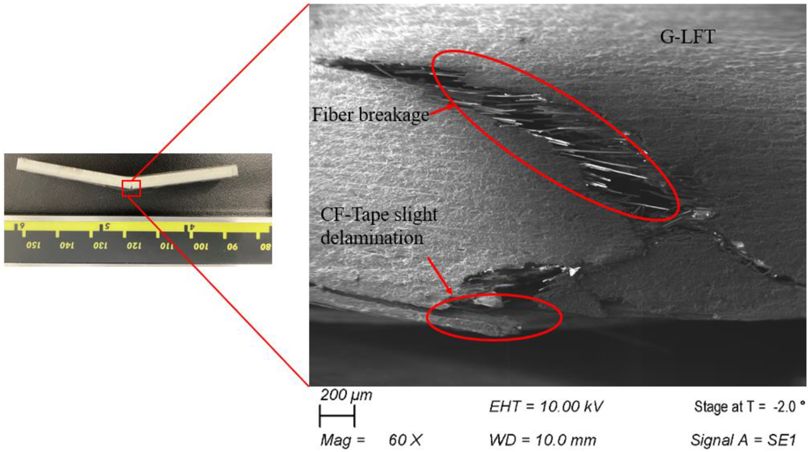
The G-LFT exhibited a single-step brittle failure, while the G-LFT/CF-Tape failed in two stages. To comprehend the two-step failure mechanism, SEM analysis was conducted on the failed specimen, as depicted in Figure 9. In the first stage, a crack was initiated in the G-LFT section and propagated towards the interface, resulting in delamination. The initiation of the crack in the G-LFT region indicates good bonding between the two surfaces. As shown in Figure 9, fiber breakage was observed within the G-LFT layer and slight delamination occurred at the CF-Tape interface. The fiber fracture ahead of the delamination zone suggests that the interfacial strength was sufficient to transfer the load before local failure occurred. These features point to a mixed failure mode involving both cohesive fracture in the G-LFT and interfacial separation. It is noteworthy that both samples were consolidated without any surface treatment. Literature suggests that the interfacial bonding can be improved by mechanical (grid blasting),
42
non-mechanical (plasma)
43
or chemical33,44 treatments. Surface treatment analysis was out-of-scope for this work and will be evaluated elsewhere. (a) The average flexural properties of the manufactured composites with and without tape. An increment of 192% in flexural strength and 120% in modulus has been noticed along the fiber direction of the tape. (b) Load versus displacement for the three-point bending testing illustrating a brittle failure in the G-LFT and the overmolded samples. SEM image of the fractured overmolded G-LFT/CF-Tape sample after flexural testing. The image shows crack initiation in the G-LFT region and slight delamination at the interface, indicating good bonding. Fiber breakage within the G-LFT and matrix remnants on the CF-Tape surface suggest a mixed cohesive-interfacial failure mode.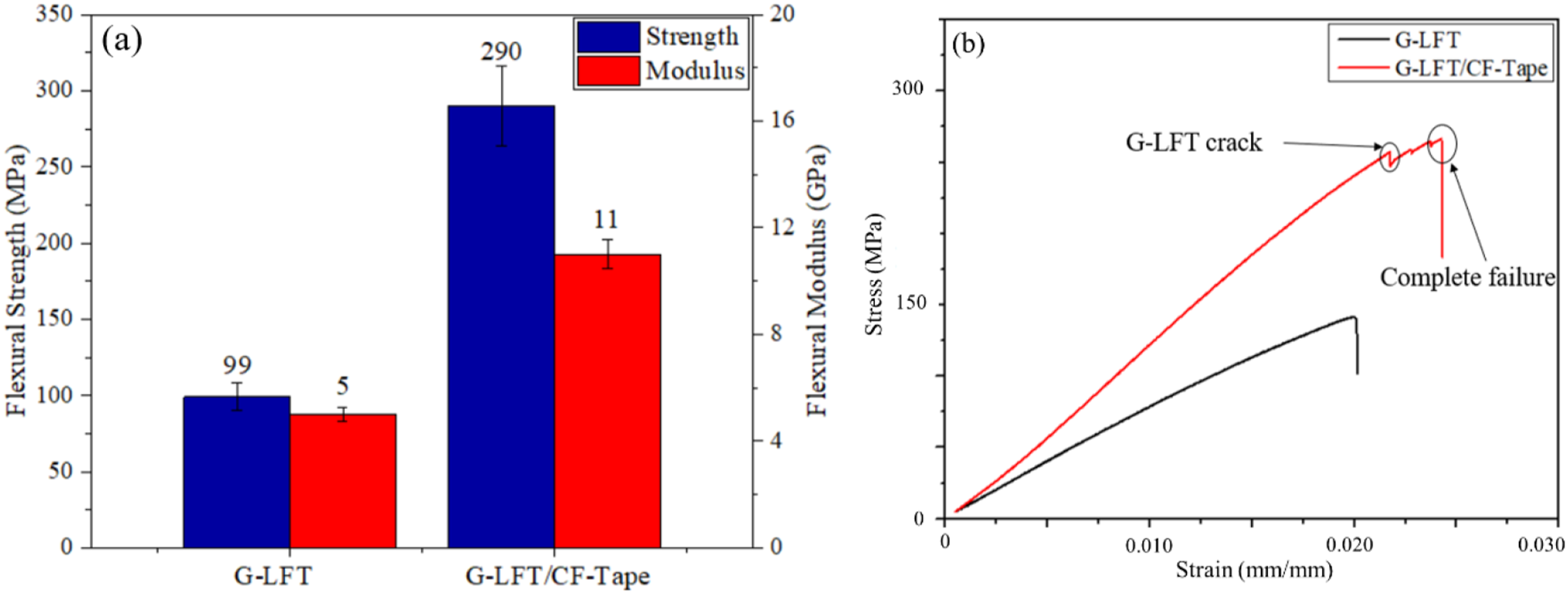
(Through-thickness) tensile strength
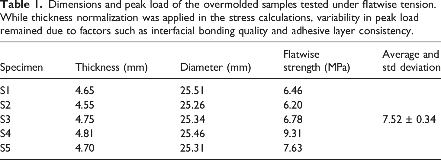
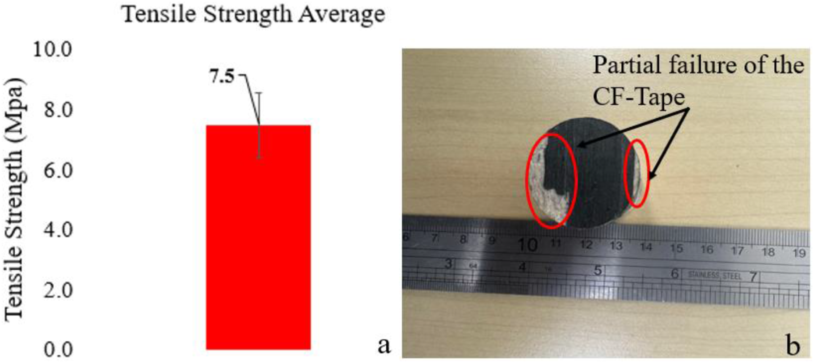
Through-the-thickness (flatwise) tests were conducted to determine the out-of-plane tensile strength of the overmolded part. A total of five specimens were tested, and the load-displacement curves are depicted in Figure 10. While all samples exhibited similar brittle failure, there was significant variation noted in the peak load. Table 1 provides the dimensions and peak load of each specimen. The failure strength was calculated by dividing the peak load by the bonded area of each specimen. Although slight thickness variations were present, they did not affect the calculated strength since the failure load was normalized by the bonded cross-sectional area. The variation in peak load primarily reflected dimensional differences, but these were accounted for in the strength calculation, resulting in a consistent average value with less than 5% standard deviation. It can be concluded that the peak load values were directly correlated with the thickness of the specimen. Thickness variation in the samples was observed during the manufacturing of substrate G-LFT. During ECM process, the hot charge (270°C) was placed on the relatively colder mold (at 65°C), resulting in uneven material flow and thickness variation. However, this variation was limited to the peak load only, and the average failure strength was 7.5 MPa with less than a 5% standard deviation, as illustrated in Figure 11(a) Quan et al.
45
showed that the flatwise tensile strength of the PEEK joints bonded by the carbon fibre prepreg attained an average of 7.6 MPa before attaining complete failure. Saeed et al.
46
achieved an out-of plane tensile strength of 7 MPa for a continuous carbon fibre reinforced 3D printed polymer composites. A partial failure of the CF-Tape at the interface was observed, as shown in Figure 11(b). This partial failure of the tape suggests strong adhesion at the interface between the G-LFT and the CF-Tape. Load-displacement curves from flatwise tensile tests of G-LFT/CF-Tape overmolded specimens. The sudden load drops indicate brittle failure behavior. Variations in peak load are attributed to differences in sample thickness, while all specimens showed similar failure mechanisms. Dimensions and peak load of the overmolded samples tested under flatwise tension. While thickness normalization was applied in the stress calculations, variability in peak load remained due to factors such as interfacial bonding quality and adhesive layer consistency. (a) Flatwise tensile strength of the G-LFT/CF-Tape overmolded part. (b) A partial failure of the CF-Tape on the interface between the G-LFT and each patch of the tape processed on the ATP.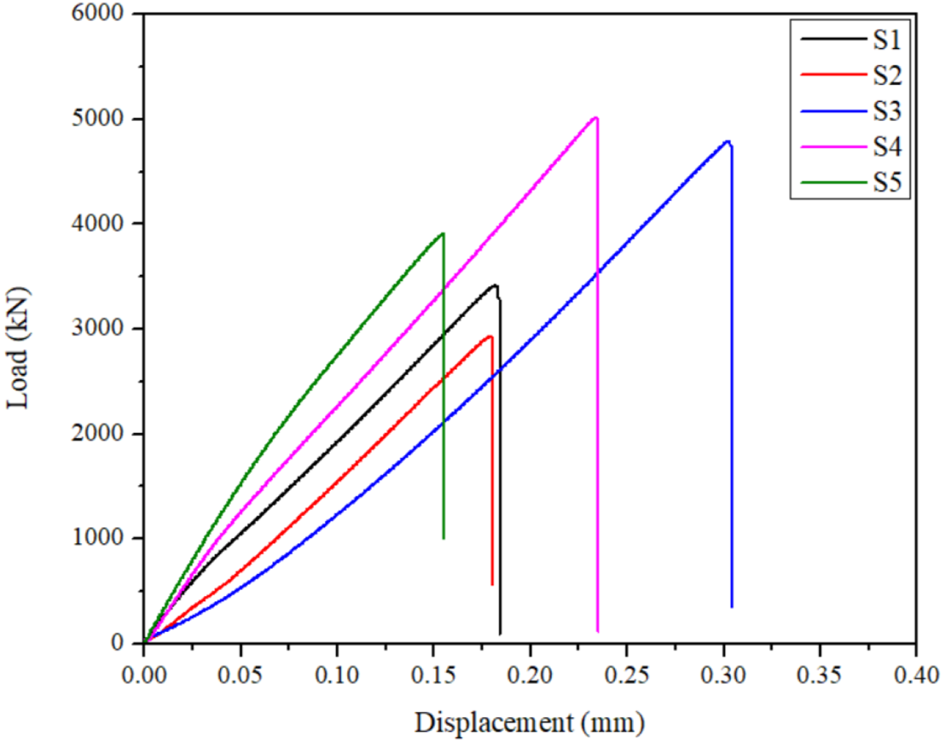
Tensile test
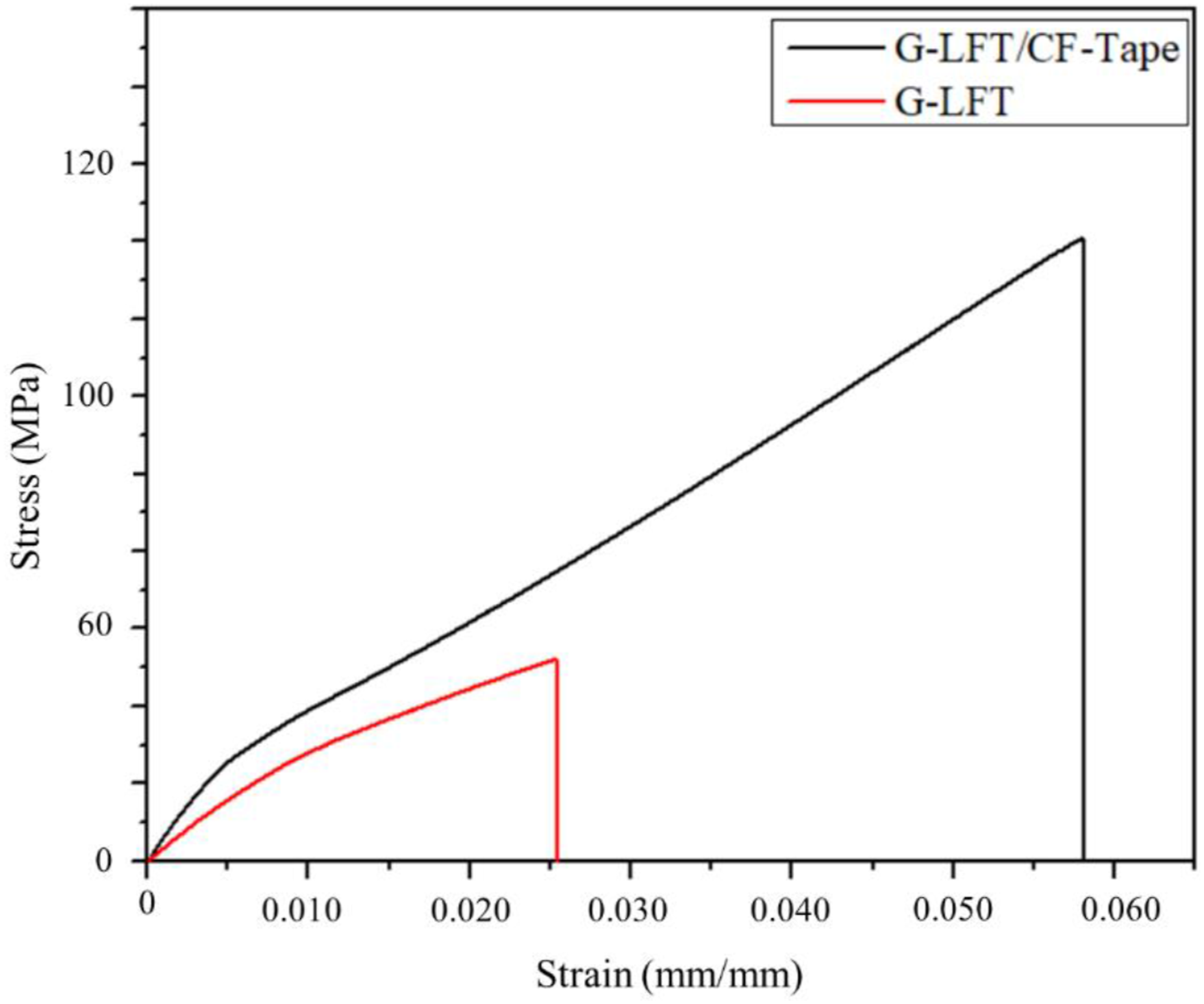
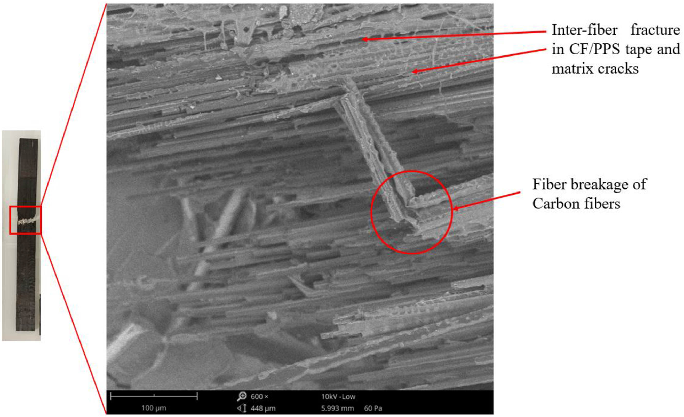
The tensile strength of the overmolded part indicates an increase from 51 MPa to 117 MPa (∼129%) in strength, and from 8 MPa to 13 GPa (∼62%) in modulus as shown in Figure 12. All specimens failed according to ASTM D3039, in the gauge length area. Figure 13 illustrate the load versus displacement for the tensile tested coupons. The linear response for the in plane tensile test and the brittle failure (sudden drop) at the ultimate strength showed a good bonding between the fiber and the matrix (G-LFT) as well as on the interface between the overmolded CF-Tape and the substrate G-LFT. SEM investigations of the overmolded G-LFT/CF-Tape samples showed that macroscopically visible inter-bundle fractures were accompanied by interfibre fractures of the CF-Tape. Matrix cracks, which grew parallel to the tensile direction were present as shown in Figure 14. Failure between fibers and the matrix and the breakage of individual carbon fibers (CF) caused the discontinuous phase to fail in the transition zone.
47
The discontinuous G-LFT mainly failed due to layers separating. Although fibers broke at a microscopic level, it became visible when whole fiber bundles failed together. As shown in Figure 13, both samples (G-LFT and G-LFT/CF-Tape) showed brittle failure at maximum load, highlighting a bond strength of 117 MPa. Tensile properties of the G-LFT and G-LFT/CF-Tape. An improvement of 128% and 62% in tensile strength and modulus, respectively, were achieved in the G-LFT/CF-Tape compared to G-LFT. Load versus displacement for the tensile test showed the failure behavior for the G-LFT and the G-LFT/CF-Tape, demonstrating a strong in-plane bonding on the interface. SEM image of the fractured G-LFT/CF-Tape interface after tensile testing. Matrix cracking and carbon fiber breakage are observed due to strong interfacial bonding, which enabled effective load transfer into the CF-PPS layer. The resulting fiber and matrix failure confirms good adhesion at the interface and the activation of composite action rather than premature delamination.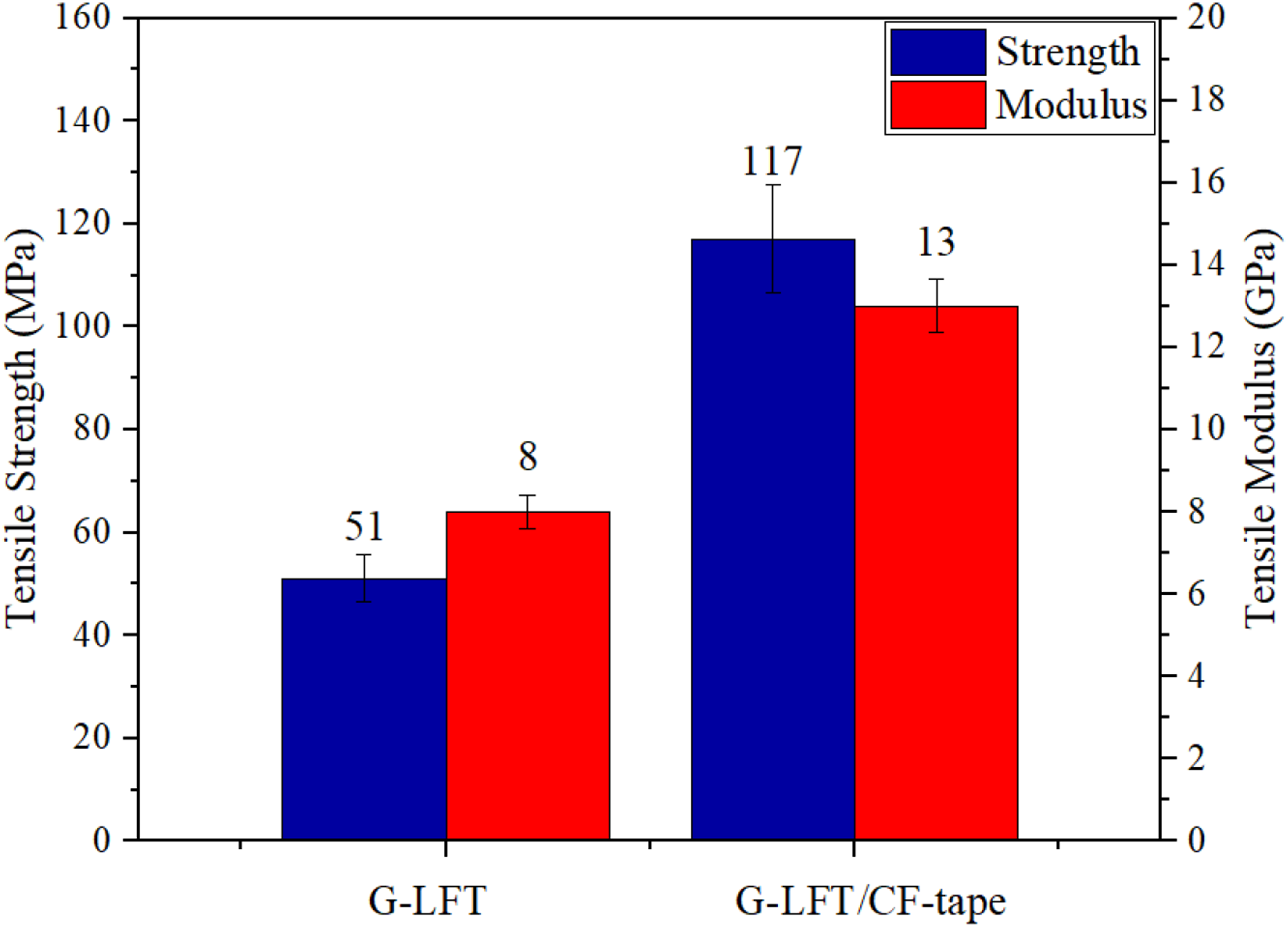
The increase in tensile (129%) and flexural (192%) strength after applying a single CF-Tape layer, despite its limited thickness (0.15–0.16 mm), can be attributed to several factors. The unidirectional continuous carbon fibers in the CF-Tape provide significantly higher stiffness and load-bearing capacity compared to the discontinuous glass fibers in the G-LFT substrate. Positioned on the tension side, the CF-Tape contributes effectively under both tensile and bending loads, particularly in flexural tests where surface stresses are critical. The enhancement is further supported by the strong interfacial bonding achieved during ATP processing, which enables efficient stress transfer from the matrix to the reinforcement. Similar findings have been reported in previous studies where thin localized reinforcements significantly improved mechanical performance due to favorable stress distribution and bonding. 48
Drop-tower (low velocity) impact test
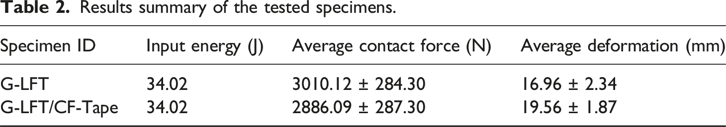
Results summary of the tested specimens.
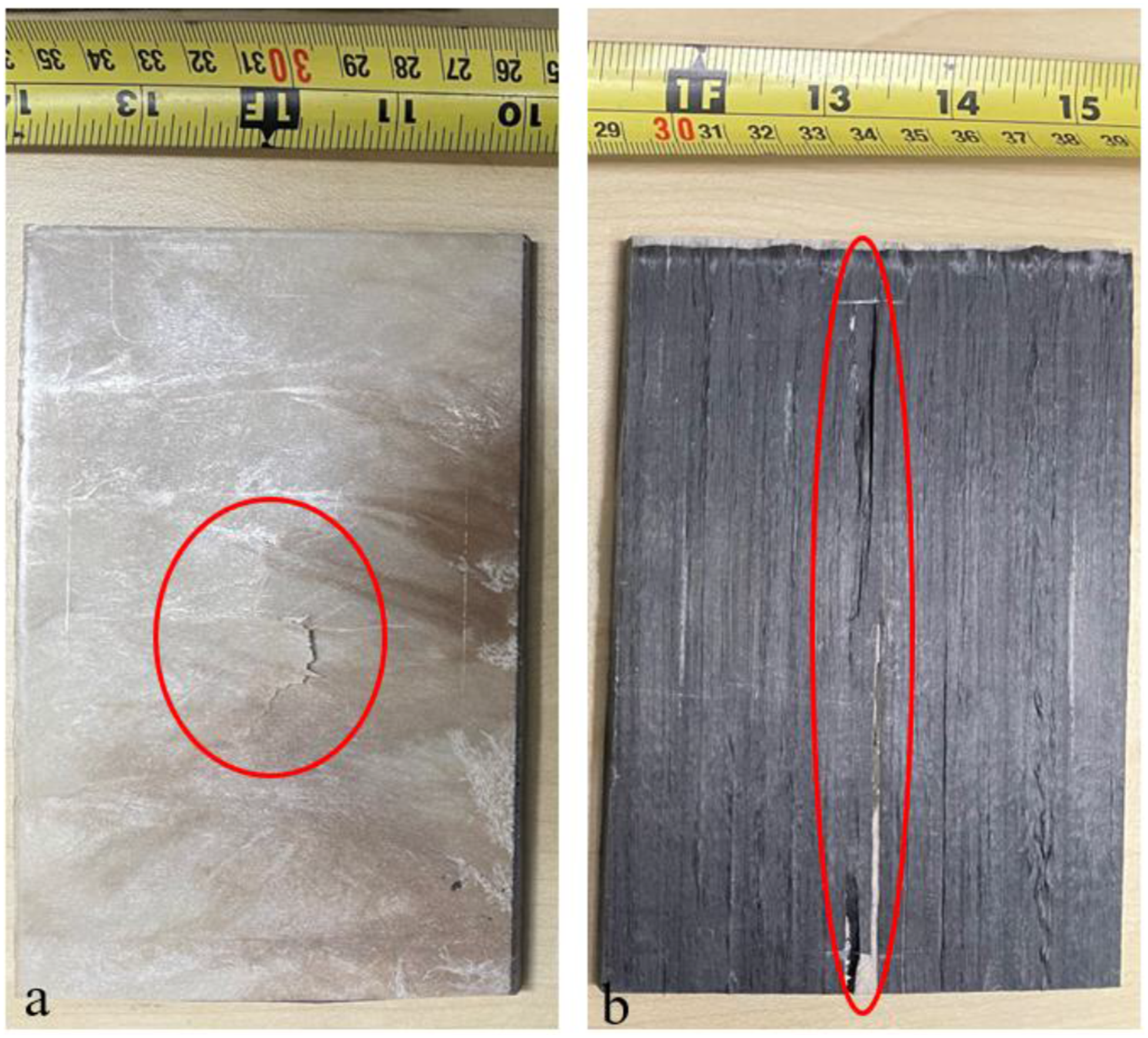
(a) 10.16 × 15.24 cm (4 × 6 in) G-LFT tested composite panels. (b) 10.16 × 15.24 cm (4 × 6 in) G-LFT/CF-Tape tested panel. A vertical crack along the direction of the CF orientation was observed in the overmolded sample. The crack orientation was observed due to the delamination of CF-Tape.
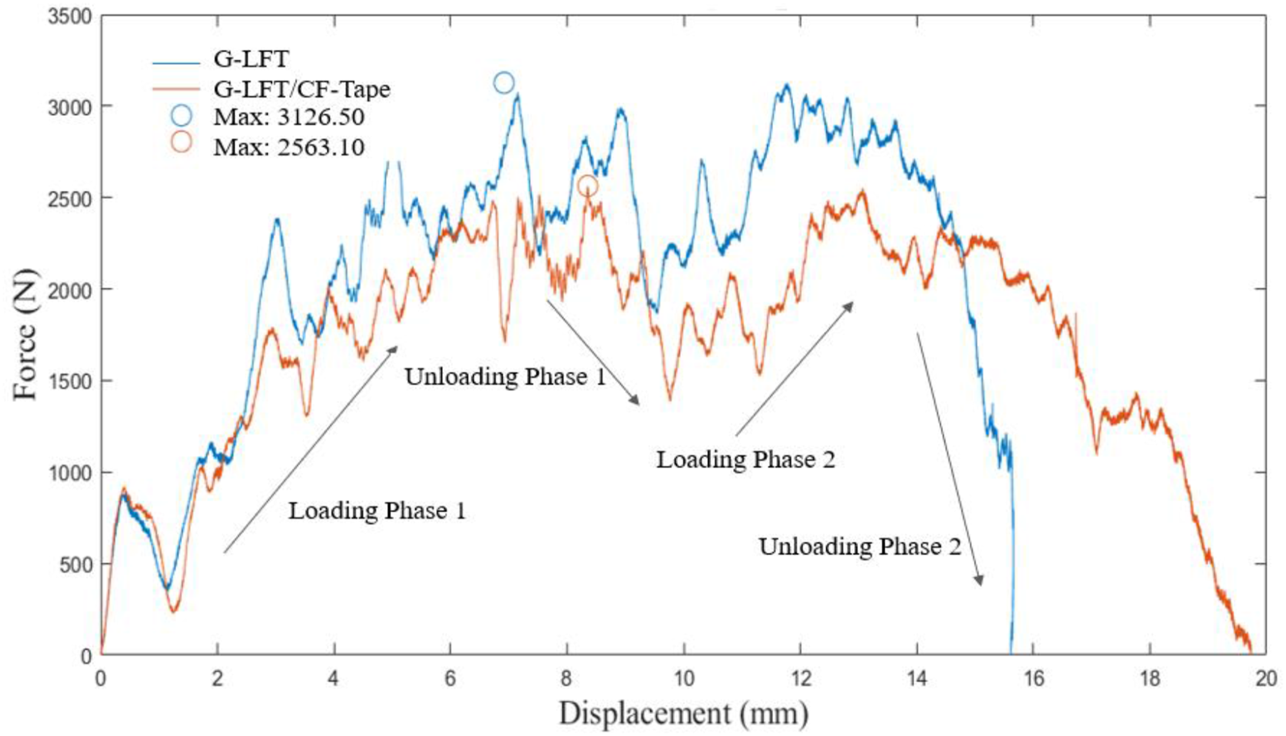
Force-displacement curves from low-velocity impact (LVI) testing of G-LFT and G-LFT/CF-Tape specimens. Both samples show a loading-unloading response typical of hybrid composites. The overmolded sample exhibits greater deformation and slightly lower peak force, attributed to energy dissipation through interfacial delamination and fiber-matrix failure mechanisms. Blue G-LFT/CF-Tape specimens, orange G-LFT specimens.
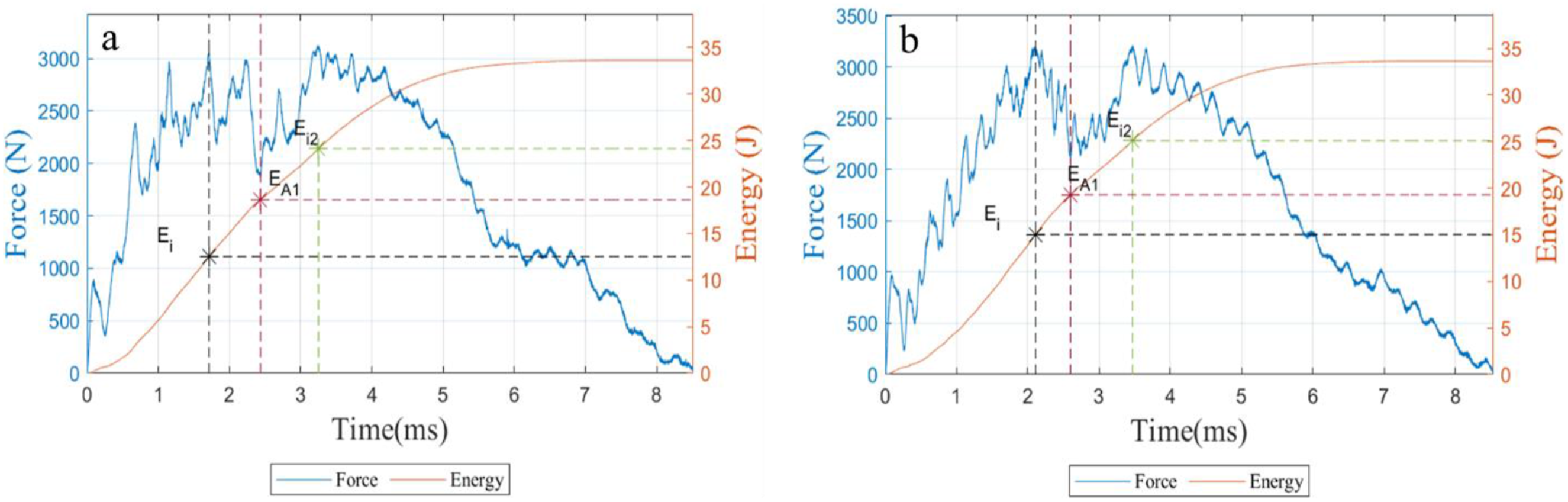
LVI force/energy-time response depicting the damage initiation energy “Ei” at both peaks and the damage propagation energy “EA” at the two minimal values during unloading phases. (a) G-LFT specimens (b) G-LFT/CF-Tape specimens.
Finite element analysis
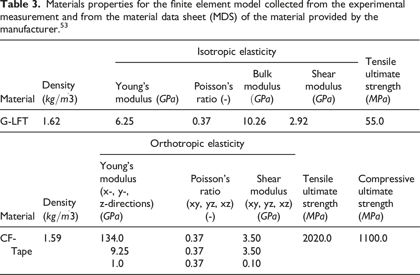
Materials properties for the finite element model collected from the experimental measurement and from the material data sheet (MDS) of the material provided by the manufacturer. 53
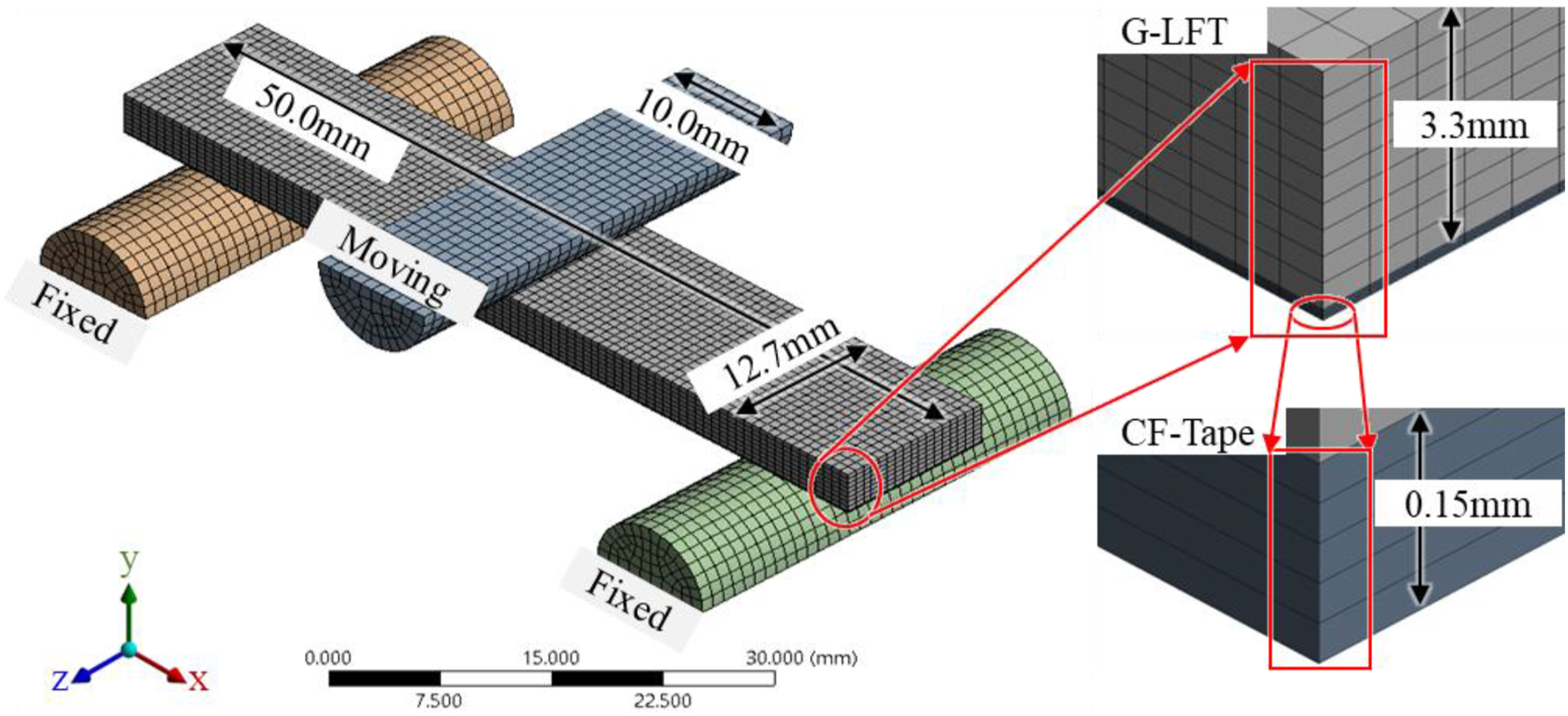
Mesh distributions for G-LFT substrate and CF-Tape layer. The figure illustrates the mesh for the tested parts and the three-point bending mechanism as rigid bodies.
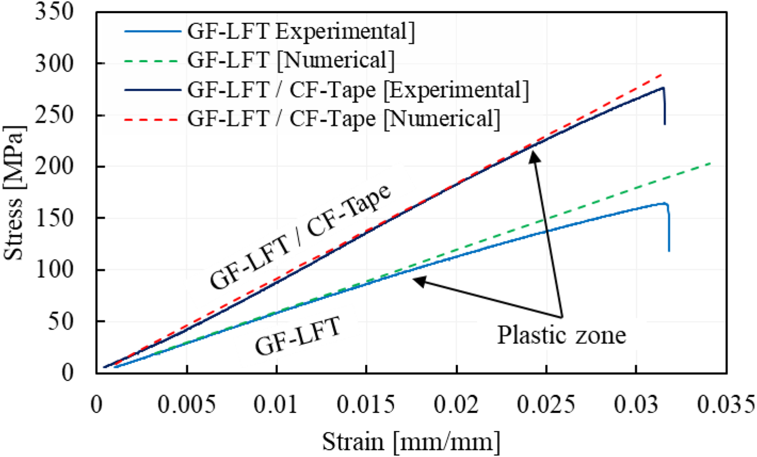
Comparison between experimental and numerical stress-strain curves for flexural testing of G-LFT and G-LFT/CF-Tape, demonstrating good agreement and validating the simulation model.
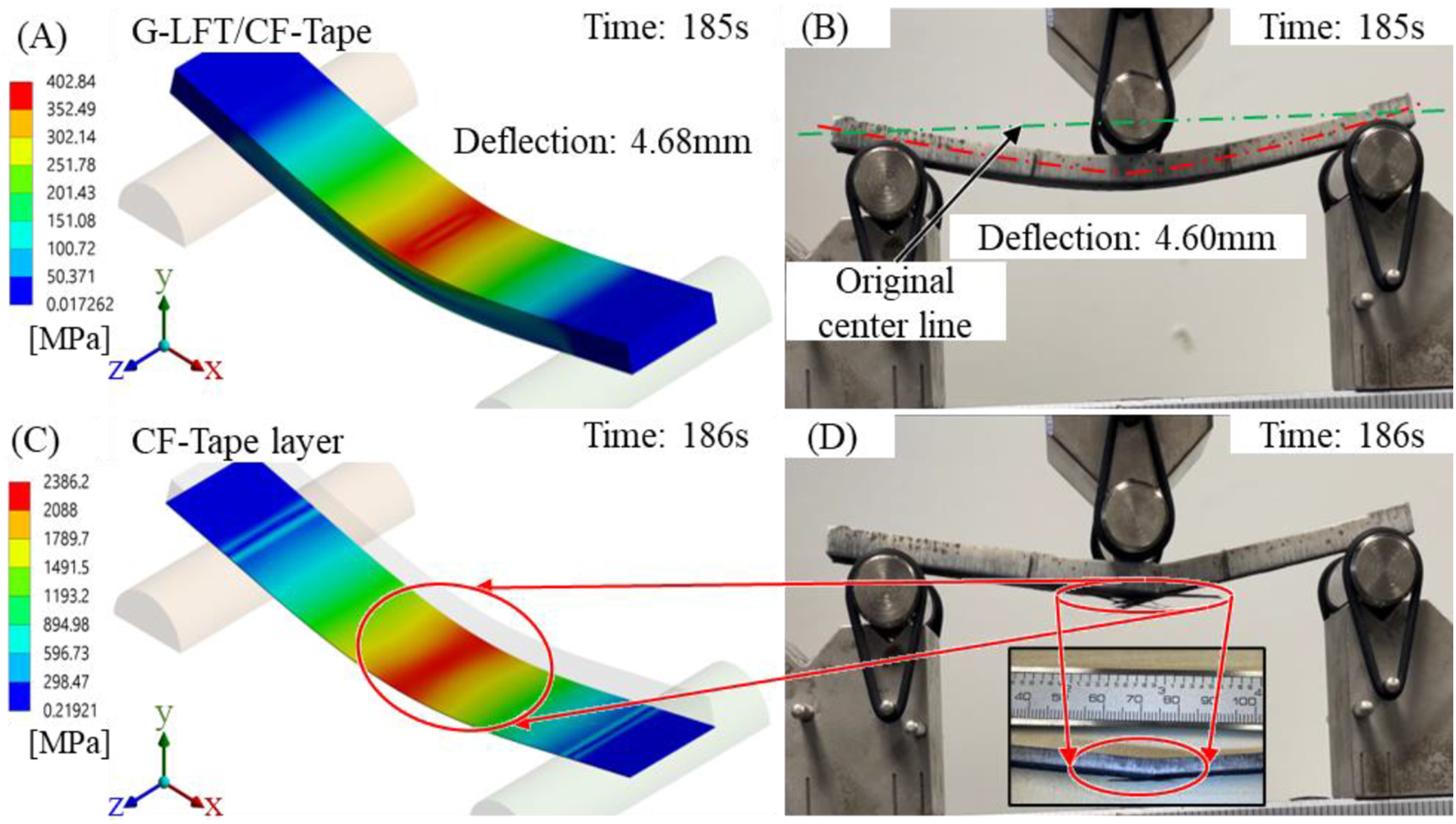
(a) Von Mises stress of the applied load, (b) Deflection of the part, (c and d) Failure monography of the CF-Tape layer numerically and experimentally respectively.
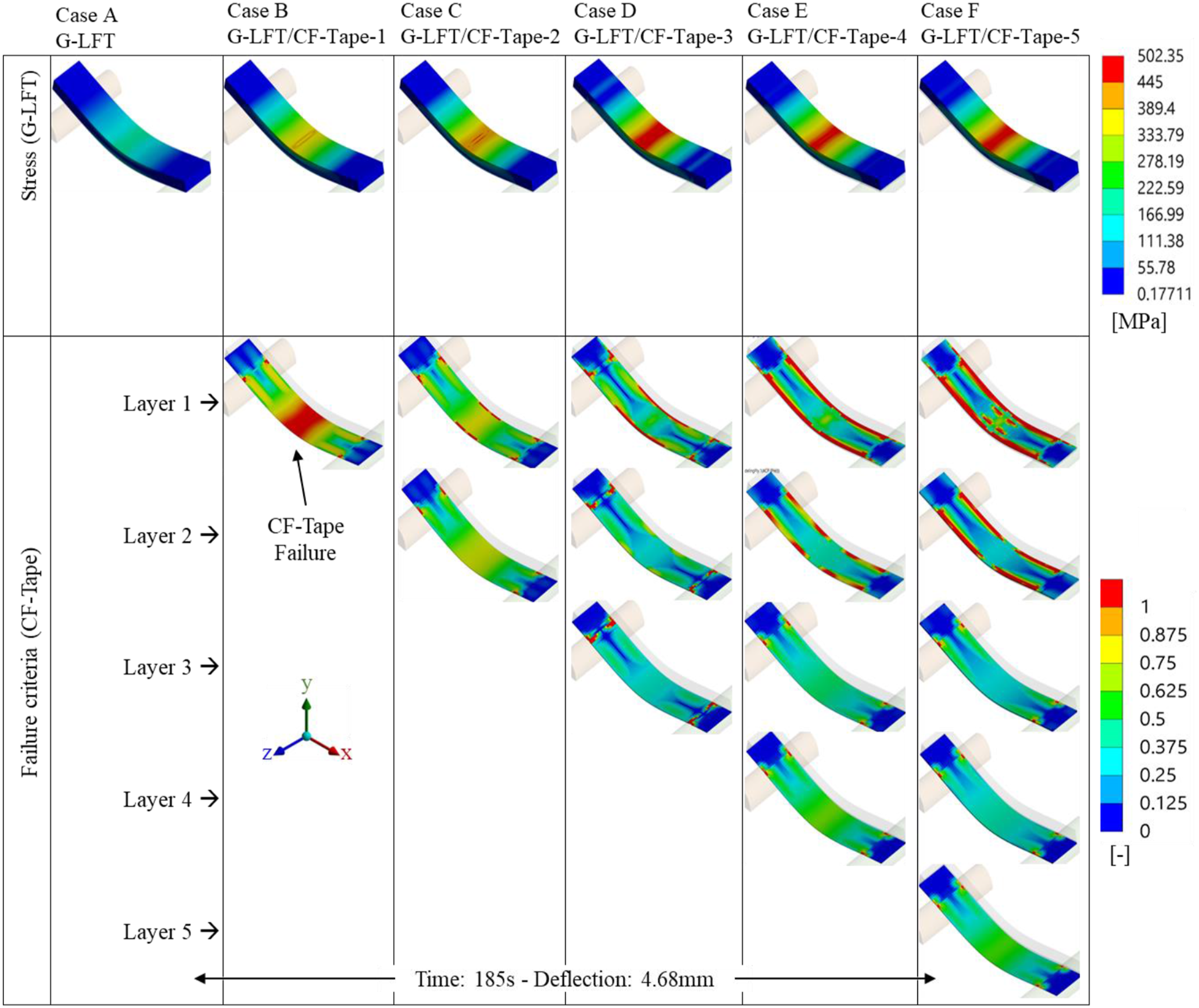
On top, Von Mises stresses for the overmolded part with different number of CF-Tape layers. The stress range shows the ability of the overmolded parts of supporting more load by adding additional layers of tapes. On bottom, the corresponding failure response of each layer individually. From the left side, the single layer of tape failed quickly, however adding more layers distributed the load evenly through thickness and prevented progressive failure.
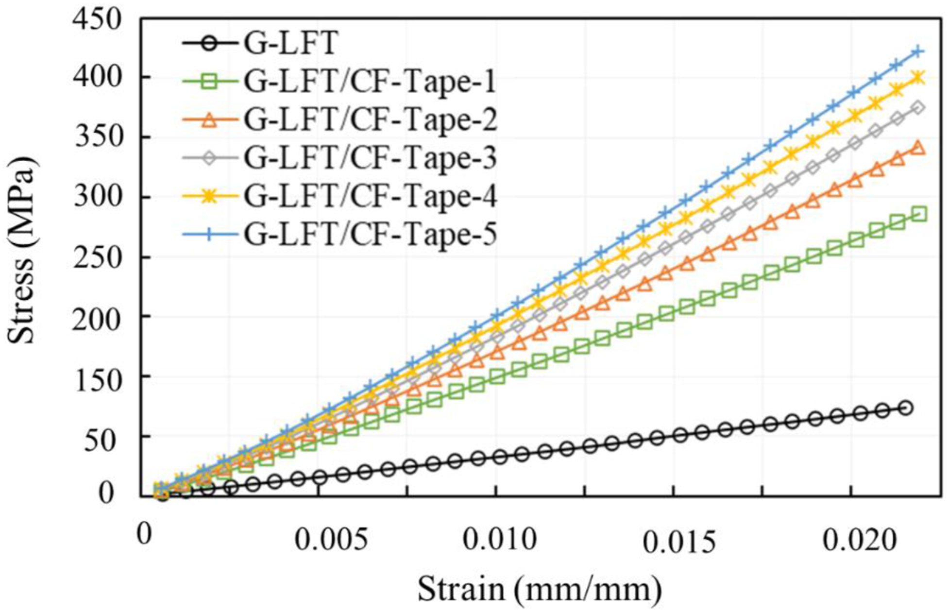
Numerical prediction of stress–strain behavior for G-LFT with increasing numbers of overmolded CF-Tape layers. The results show that adding CF-Tape layers progressively enhances the composite’s stiffness and ultimate strength, indicating improved load-bearing capacity and more efficient stress distribution.
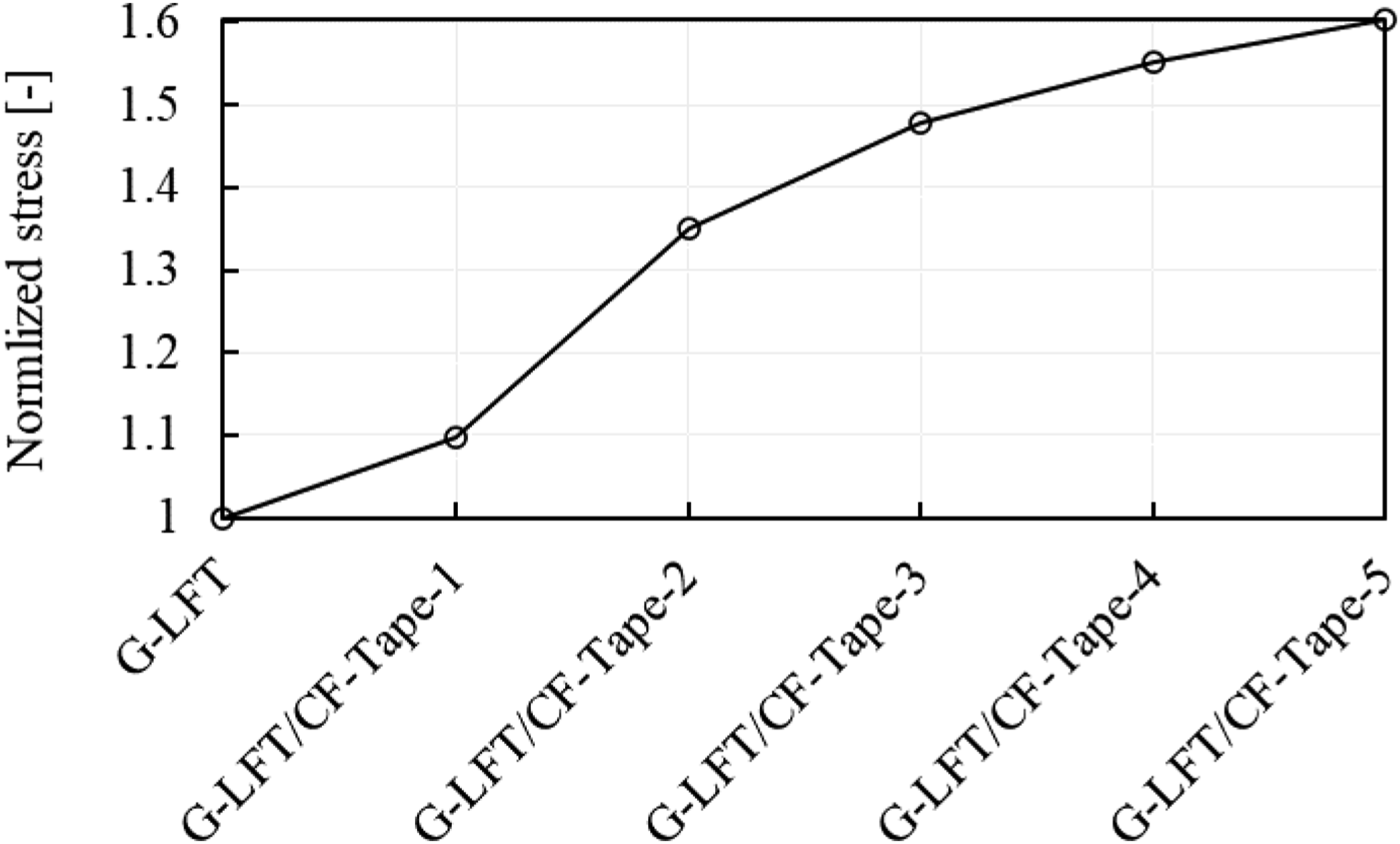
Normalized stress predictions showing the strengthening effect of multiple CF-Tape layers overmolded onto G-LFT, with up to 60% improvement after five layers.
Conclusions
The aim of this work was to manufacture and characterize an overmolded part using two different techniques, the ECM has been selected as an industry scale manufacturing technique, with a rate of 1 part/min (discontinuous part) to produce the G-LFT substrate, while the ATP was selected among the traditional technique of laying down UD-tape. The ATP has been conducted in the study to enhance the local strength of the part, with high speed, efficiency, and automation. The final overmolded composite showed an enhancement of ∼190% in flexural strength and ∼110% in modulus. The tensile strength and modulus increased by 128% and 62% respectively. The interface bonding was investigated using SEM and OM before and after testing, the captured imaged showed a good bonding on the interface between the G-LFT and the CF-Tape. A slight delamination was noticed after the mechanical testing. However, the mechanical property of the whole part was not affected. For that purpose, the effect of mechanical and non-mechanical treatment(s) would be studied in the future to improve the interface bonding between the CF-Tape with the substrate. An Ansys based FEA model was used to study the effect of overmolding CF-Tape layers on strengthening the long glass fiber thermoplastic. The addition of CF-Tape layers enhances ultimate strength and stress distribution in the long glass fiber thermoplastic part. The model showed the gradual increase in strength of maximum 60% by adding five layers of CF-Tape. The model also allows for simulation of CF-Tape layers with varying fiber orientations, providing flexibility to assess different reinforcement strategies and their impact on localized strength.
Footnotes
Acknowledgements
This manuscript has been authored by UT-Battelle, LLC, under contract DE-AC05–00OR22725 with the US Department of Energy (DOE). The US government retains and the publisher, by accepting the article for publication, acknowledges that the US government retains a nonexclusive, paid-up, irrevocable, worldwide license to publish or reproduce the published form of this manuscript, or allow others to do so, for US government purposes. DOE will provide public access to these results of federally sponsored research in accordance with the DOE Public Access Plan (![]() ). The Authors gratefully acknowledge the Institute of Advanced Composites Manufacturing Innovation (IACMI) under award number A22-1469. Additionally, authors want to thank Southeastern advanced machine tools network (SEAMTN) under award number HQ00052110069 for funding a part of the project and National Science Foundation (NSF), Industry-University Cooperative Research Centre (IUCRC) under grand number NSF-2052738 for offering technical assistance and resources.
). The Authors gratefully acknowledge the Institute of Advanced Composites Manufacturing Innovation (IACMI) under award number A22-1469. Additionally, authors want to thank Southeastern advanced machine tools network (SEAMTN) under award number HQ00052110069 for funding a part of the project and National Science Foundation (NSF), Industry-University Cooperative Research Centre (IUCRC) under grand number NSF-2052738 for offering technical assistance and resources.
Declaration of conflicting interests
The author(s) declared no potential conflicts of interest with respect to the research, authorship, and/or publication of this article.
Funding
The author(s) disclosed receipt of the following financial support for the research, authorship, and/or publication of this article: this work was supported by the IACMI: A22-1469, SEAMTN: HQ00052110069 and National Science Foundation: NSF-2052738.