
Abstract
Automated Fiber Placement (AFP) offers precise and flexible composite manufacturing but is prone to defects, with overlaps being among the most common. Once formed, overlaps disrupt compaction pressure, an important process parameter, leading to poor bonding between adjacent prepreg tows and initiating defects such as wrinkling and bridging. In this study, alternative polyurethane compaction rollers with varying shaft diameters (candidate rollers) were manufactured and compared with series of polyurethane and rigid rollers (reference rollers) to reduce pressure inconsistency while maintaining adequate compaction pressure during AFP of thermoset prepreg tape. Experimental tests, microscopic imaging, and finite element method (FEM) analysis were used to evaluate how each roller localized pressure non-uniformity that occurs adjacent to an overlap. Reference rollers produced non-uniform bonding thickness across the tape width once an overlap was present on the adjacent tow, whereas candidate rollers (with shaft diameters increased from 25 mm to 28 mm, 32 mm, and 35 mm combined with softer polyurethane) maintained more uniform bonding. Single-lap joint tests and FEM simulations confirmed that candidate rollers effectively minimized pressure inconsistency. Overall, results show that managing overlaps while sustaining high compaction pressure is best achieved by increasing shaft diameter and using a soft polyurethane layer rather than relying on higher-stiffness polyurethane.
Introduction
Carbon fiber-reinforced polymers (CFRPs) combine high specific strength, stiffness, low weight, and fatigue resistance, making them essential in demanding applications.
1
To support their use in complex, large-scale structures, manufacturing methods must deliver precision and efficiency.1–3 Automated fiber placement (AFP) addresses these needs by offering high-speed deposition, reduced material waste, and compatibility with manufacturing large-scale components.4,5 This manufacturing method employs a robotic head (Shown in Figure 1) with a heating system and compaction roller,
4
where parameters such as pressure and heat control directly govern tow bonding quality and prepreg tackiness.
6
Automated fiber placement (AFP) machine consisting of a robotic head equipped to deposit prepreg tows, apply compaction pressure using a compaction roller, and supply heat through a torch or laser.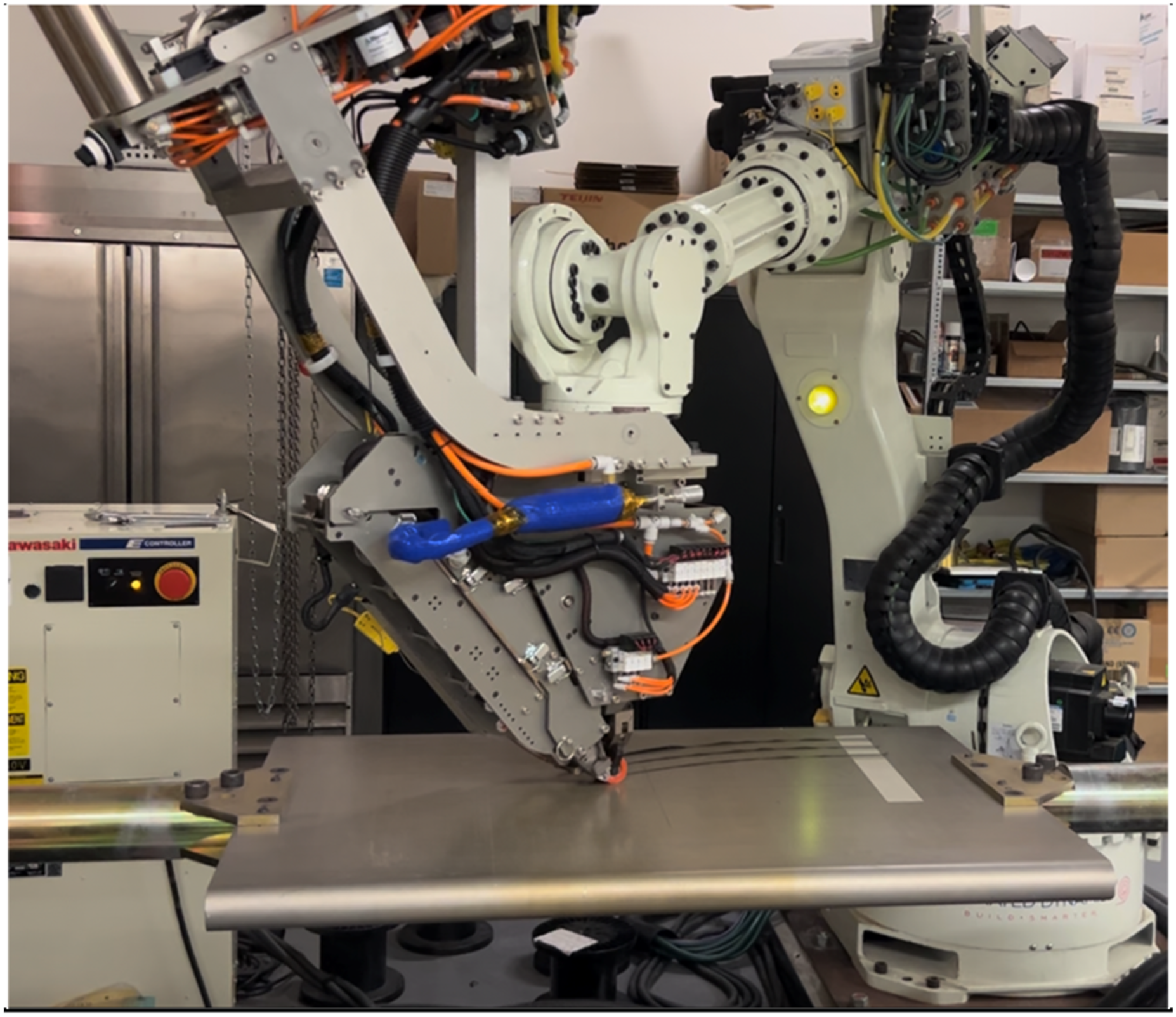
Despite its advantages, AFP presents certain challenges and inevitable occurrence of various defects.7–11 Hence, understanding these defects and developing methods to prevent or minimize their formation has remained a popular research topic in AFP manufacturing method. Real-time monitoring methods have been developed to track process-induced states and layup defects during automated placement. Yadav et al. 12 used embedded fiber Bragg grating (FBG) sensors for in-line residual strain monitoring during automated tape layup, linking processing conditions to strain build-up. In addition, Tang et al. 13 proposed an in-situ AFP defect inspection approach using structural-light 3D scanning and PointNet++ point-cloud segmentation, achieving sub-second defect localization for out-of-plane defects such as wrinkles, bridging, and puckers. In 14 studies demonstrated that the stiffness of the compaction roller strongly influences layup quality and laminate porosity in thermoset AFP; soft perforated polyurethane rollers induced wrinkles and voids, whereas rigid rollers produced smoother, defect-free surfaces. These findings highlight the importance of pressure uniformity and roller design in minimizing defects. However, rigid rollers exhibit poor formability, which limits their ability to conform to complex molds or surface irregularities. 15 Moreover, with rigid rollers, the possibility of tuning process parameters is limited. M. Kheradpisheh et al., 9 used the possibility of tuning process parameters that polyurethane rollers offer to mitigate wrinkles caused by steering and out-of-plane deformation. To do so they employed a concave-shaped polyurethane roller, which facilitates local adjustment of process parameters. Process parameters such as compaction load, pressure, feed rate, and temperature play a major role in determining layup quality of thermoset prepreg tow. Bakhshi and Hojjati 16 showed that solid polyurethane rollers outperform perforated ones by providing more uniform pressure distribution and reducing defects such as blisters and wrinkles. In 17 wrinkle formation during tow steering in AFP had been modeled, highlighting prepreg tackiness as a key factor influencing adhesion and steering limits. They showed that higher tack improves layup stability by reducing the critical steering radius, while insufficient tack promotes wrinkling and tow pull up. Studies also had been conducted to develop a force correction and control method for AFP to maintain compaction pressure within an optimal range, thereby improving bonding uniformity and reducing defects on complex surfaces. 18 He et al. 19 demonstrated that segmented rollers improve both global and local pressure uniformity, minimizing bridging and wrinkles. Lu et al. 20 developed a finite element model to evaluate compaction pressure distribution in automated dry fiber placement (ADFP), showing how roller material, tool curvature, and substrate thickness affect pressure uniformity, and providing force-control adjustments for process optimization with different roller materials. These parameters also influence uncured prepregs, which can be further examined through appropriate testing methods. Authors in 21 showed that variations in pressure, contact time, and temperature affect resin flow, fiber penetration, and ultimately bonding shear strength, highlighting the critical role of compaction pressure.
These studies collectively highlight the critical influence of process parameters such as compaction pressure, feed rate, temperature, and roller stiffness on the overall layup quality and defect formation in thermoset AFP. Overlap is among defects that its presence can alter process parameters. Li et al. 22 shown that gaps and overlaps introduce local thickness variations and out-of-plane waviness, leading to non-uniform compaction pressure, resin redistribution, and strength reduction within AFP laminates. Diemar et al. 23 used micro-computed tomography to characterize fiber waviness and ply thickness variation from gaps and overlaps, incorporating these features into meso-scale FE models. Results showed up to 12.4% tensile strength reduction, confirming that overlap-induced waviness and local strain concentrations degrade laminate performance. Although efforts had been done to develop a system to predict gaps and overlaps, yet these defects still arise during layup. 24
Once an overlap forms during layup, it can influence subsequent layers and act as a source for additional defect development at uncured stage. Rajan et al. 25 showed that overlaps in the substrate create small surface height variations that disturb adhesion, leading to localized wrinkle formation. They further observed that when overlaps are combined with tighter steering radii, these wrinkles intensify, producing larger amplitudes and more irregular wrinkle patterns that compromise layup quality. Hojjati and Yas 26 demonstrated that overlaps can disrupt pressure distribution under the compaction roller, creating zones with insufficient or zero pressure adjacent to the overlap with the extent of these affected zones depends on the roller type. These affected zones are the area that compaction rollers failed to apply compaction pressure and hence tack is reduced. In 27 , it is suggested that improper tack can promote the formation of bonding defects such as wrinkles, buckles, and bridging.
Crossley et al. 28 reported that the uncured prepreg exhibits pressure sensitive tack, with its magnitude being strongly dependent on temperature and feed rate. Belhaj et al. 29 experimentally investigated the tackiness of AFP prepregs, emphasizing its critical role in achieving stable bonding and preventing layup defects such as tow pull-up, bridging, and wrinkling. The effects of temperature, pressure, and feed rate on prepreg tack were quantified via peel tests; a Taguchi method was utilized to reduce the number of experimental tests. Findings in 30 concluded that the interactions among process parameters play a significant role in determining tack performance. Their findings indicated that higher feed rates require elevated temperatures to maintain adequate tack, while the temperature effect varies notably between low and high compaction loads. Crossley et al. 31 quantified uncured prepreg tack via peel tests, showing strong dependence on temperature and feed rate, and suggesting that insufficient tack induces first ply peel and layup instability.
Cured laminates containing overlap or overlap related defects (such as wrinkles and fiber waviness) have also been widely investigated. Ju et al. 32 showed that fiber waviness that was caused due to formation of gaps and overlaps during layup, significantly reduces laminate strength (up to 30% in compression) highlighting the need to minimize such defects. Studies by Y. Tang et al. 33 showed that wrinkles caused by tow offset induced gaps and overlaps in AFP laminates reduce flexural strength by about 12–15%, leading to increased warping and delamination. Their results emphasize that tow misalignment and resin accumulation significantly impair laminate integrity.
Based on the literature review, overlaps in AFP of thermoset composite laminates affect both the layup process and the mechanical performance of the final laminate by disrupting pressure distribution and reducing tack, which can initiate defects such as wrinkles. While soft polyurethane rollers conform better to surface irregularities, they provide insufficient compaction pressure. This study proposes an alternative roller design approach that balances formability and compaction pressure to minimize affected zones. Rollers manufactured based on this design approach (Candidate rollers) are compared with series of rigid and polyurethane rollers (Reference rollers) under various overlap conditions to identify the most effective configuration for maintaining pressure uniformity during the uncured stage.
Overlap defect in the AFP process
Understanding how overlaps affect layup quality is essential for developing a solution to minimize their impact. An overlap influences compaction pressure because it results in a local height difference at the layup surface. This local height difference can significantly disturb the pressure distribution under the compaction roller. Areas adjacent to the overlap will experience this non-uniform pressure and may receive reduced or even zero compaction pressure. Based on the type of roller, non-pressure zones can be wider or narrower. Sections of prepreg tapes that receive insufficient compaction pressure will form a poor bond with their underlying layer (Whether it is another ply or the mould). Thermoset composites will be cured in an autoclave after the layup, which will improve bonding. However, at the uncured stage and during layup, these affected zones will act as initiation sites for other defects such as bridging, wrinkles, and tape folding. Although poor bonding itself can be eliminated in an autoclave, the resulting defects of it during layup will stay in the laminate, and the following curing cycle of autoclave is not capable of eliminating these defects.
The compaction roller has an effective role in this matter. In Figure 2(a), a front view of a two-layer layup with a layup sequence of [0,0] (Fibers along the Z-Direction) without overlap is shown, displaying a smooth surface. In Figure 2(b), the same layup sequence is illustrated with an overlap formed on the second ply. When encountering overlaps, rigid compaction rollers tend to rest on the surface’s highest point, which is the top of the overlap. Based on experiment observations, polyurethane compaction rollers improve this behaviour and as shown in Figure 2(d), exhibit formability. In the case of polyurethane rollers, the roller’s surface deforms over a distance L (shown in Figure 2(d)), compromising the bond quality over this region, which can be reduced by utilizing soft polyurethane rollers. To improve bonding quality, a proper compaction pressure at any area close to the overlap is essential, meaning reducing the value of L is essential. (a) Front view schematic illustration of a two-layer layup: without overlap, (b) with an overlap formed in the second row, (c) a polyurethane compaction roller moving along Z-direction with an overlap underneath it (d) applying pressure over the row with an overlap.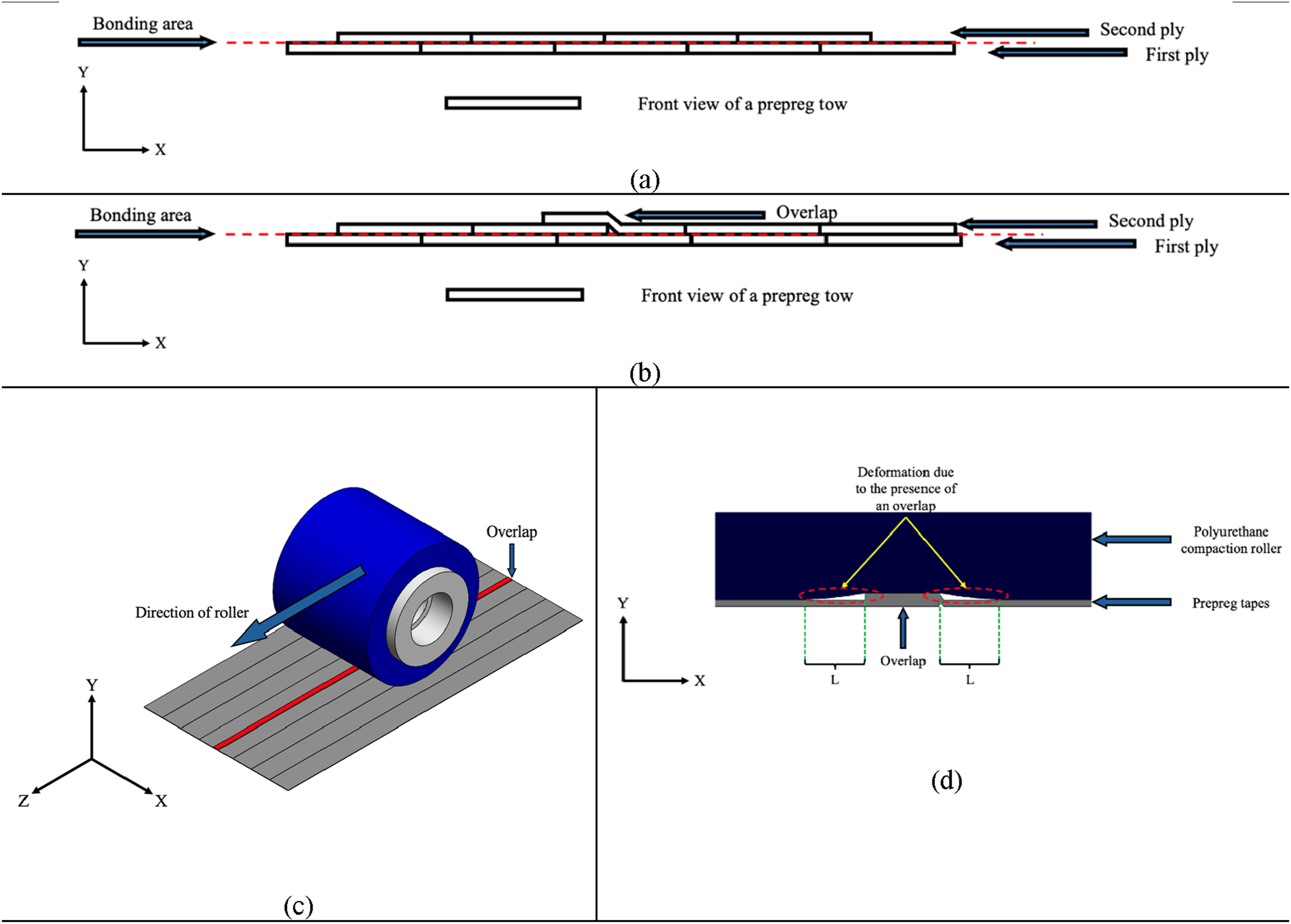
Design approach for improved pressure uniformity
In the previous section, it was shown that polyurethane rollers outperform rigid rollers in terms of forming proper bonding when overlaps are present. Soft polyurethane rollers improve formability and result in narrower affected zones; however, this type of rollers has inherent limitations. Because of their low maximum compaction pressure, increasing the applied load does not significantly raise peak pressure and may instead cause resin push-out. 9 Conversely, stiffer polyurethane rollers can achieve higher pressures but at the cost of reduced formability, producing wider affected zones (larger values of L) around overlaps. In this work, rollers of this approach are referred to as the reference rollers.
In alternative proposed approach, the shaft diameter is increased to provide a stiffer core while maintaining a soft outer polyurethane layer for better formability. The total outer diameter was fixed at 38 mm to ensure compatibility with the AFP machine, resulting in the following constraints:

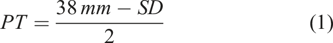
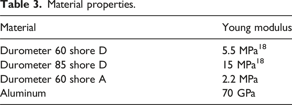
Where SD is the shaft diameter and PT the polyurethane thickness. Polyurethane of durometer 60 Shore A was selected for its low stiffness. As illustrated in Figure 3(d), while the outer diameter remained fixed at 38 mm, the polyurethane thickness decreased as the shaft diameter increased. SD value ranges from 25 mm (reference rollers) to 38 mm (rigid stainless-steel roller, SSR). In this study, three candidate rollers with shaft diameters of 28 mm, 32 mm, and 35 mm were manufactured using 60 Shore A polyurethane. In addition, since the available reference rollers were made from polyurethane 60 Shore D (Shore D is stiffer than equivalent Durometer Shore A), a 25 mm roller with durometer 60 Shore A was fabricated for comparison purposes. It is worth noting that Shore A and Shore D are different scales for measuring the indentation hardness of rubbers and polyurethanes (ASTM D2240 [34]). Therefore, the same numerical value on different scales (e.g., 60A vs 60D) does not indicate the same hardness, since the scale (Shore A and Shore D) is different (Table 1). (a) Side view schematic of the reference roller, showing the fixed total diameter (38 mm) and the variable shaft outer diameter (25, 28, 32, and 35 mm). (b) Manufacturing of the candidate rollers, featuring CNC-machined molds and diamond knurled shafts (c) All the utilized compaction rollers (reference rollers and candidate rollers) (d) Detail of perforated roller dimensions. Naming of the compaction rollers utilized in this study.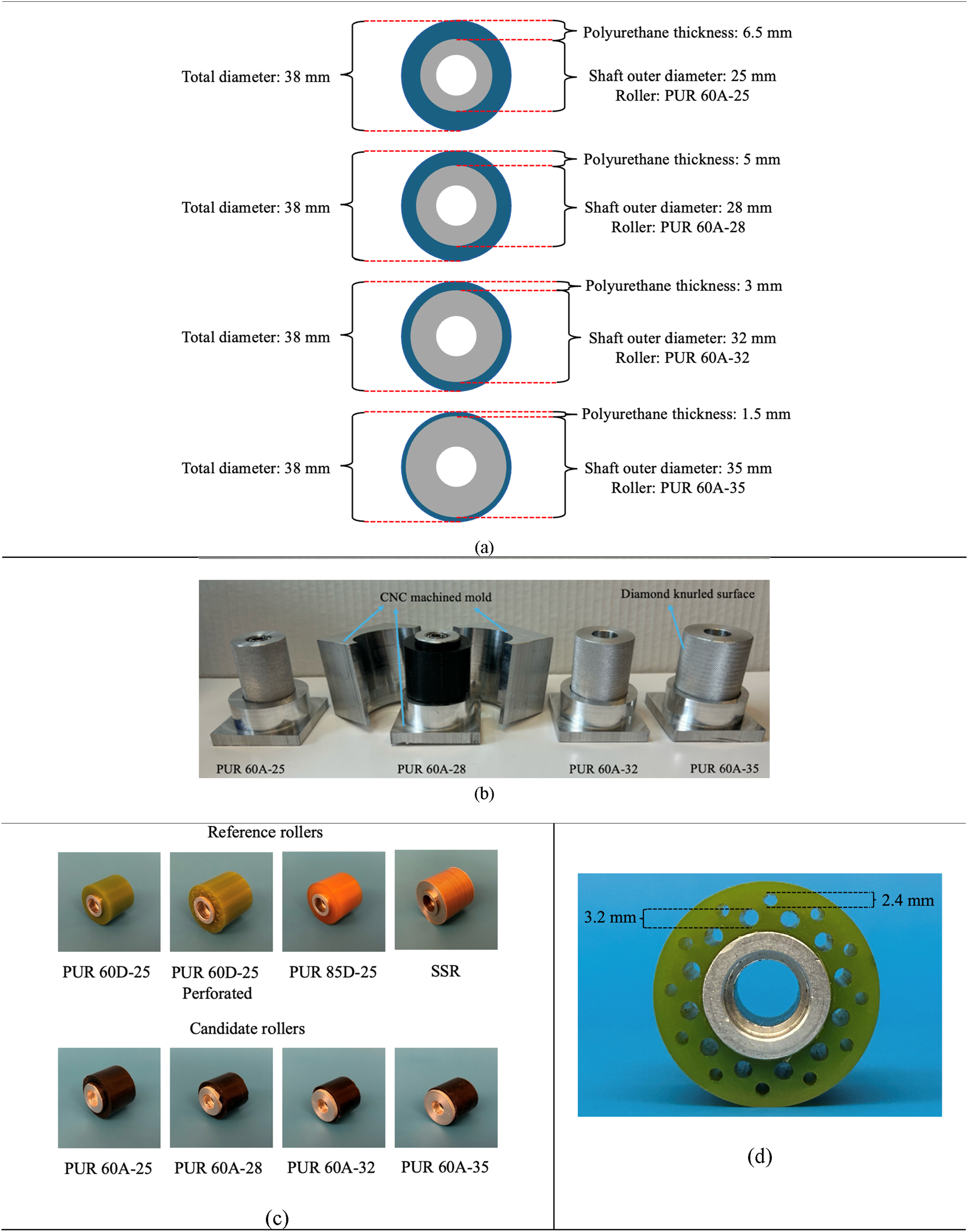
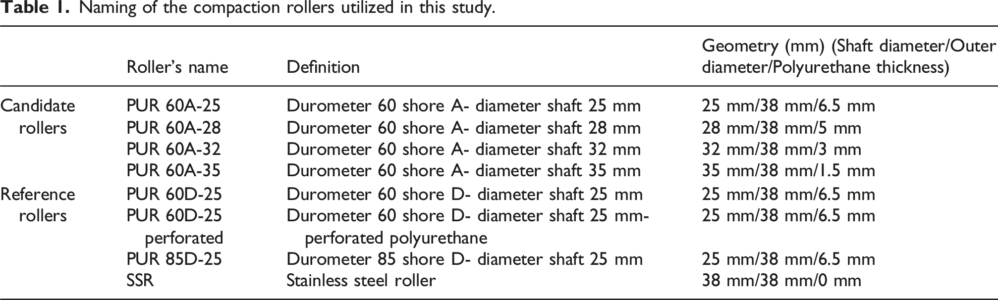
Hereafter, this approach is referred to as the candidate roller design, and the corresponding rollers are termed candidate rollers, since their performance is under evaluation. In this work, rollers of this alternative approach are referred to as candidate rollers. For clarity, the following naming convention is adopted for the rollers used in this study:
Fabrication of candidate rollers
A mold and four shafts with varying diameters were fabricated for roller design illustrated in Figure 3(a). Each shaft surface was diamond knurled to enhance bonding with the polyurethane. The mold, CNC-machining from aluminum, provided a smooth surface finish for the roller. Figure 3(b) shows the prepared shafts, ready to be cast, and PUR 60A-28 that had already been cast. To improve quality, the polyurethane resin was degassed at 0.2 bar to eliminate entrapped air in the polyurethane. With the candidate rollers manufactured and the reference rollers available, all compaction rollers used in this study are presented in Figure 3(c). Among the reference rollers, the perforated roller contains holes of two different sizes in its polyurethane layer, as illustrated in Figure 3(d).
Materials and experimental procedure
The experimental material was an uncured unidirectional carbon fiber/epoxy prepreg tape (CYCOM 977-2, Bombardier Inc., Canada) with a 6.3 mm width, 0.14 mm thickness, and fiber fraction of 60%. An in-house setup (Figure 4) simulated AFP process parameters: compaction load applied by a pneumatic arm and feed rate controlled by a motorized rail. This system is particularly valuable in this study, where precise layup is required for the experimental tests. In-house experimental setup designed to simulate the applied compaction load and feed rate conditions representative of AFP manufacturing, which consists of a pneumatic arm, a compaction roller, and a motorized rail.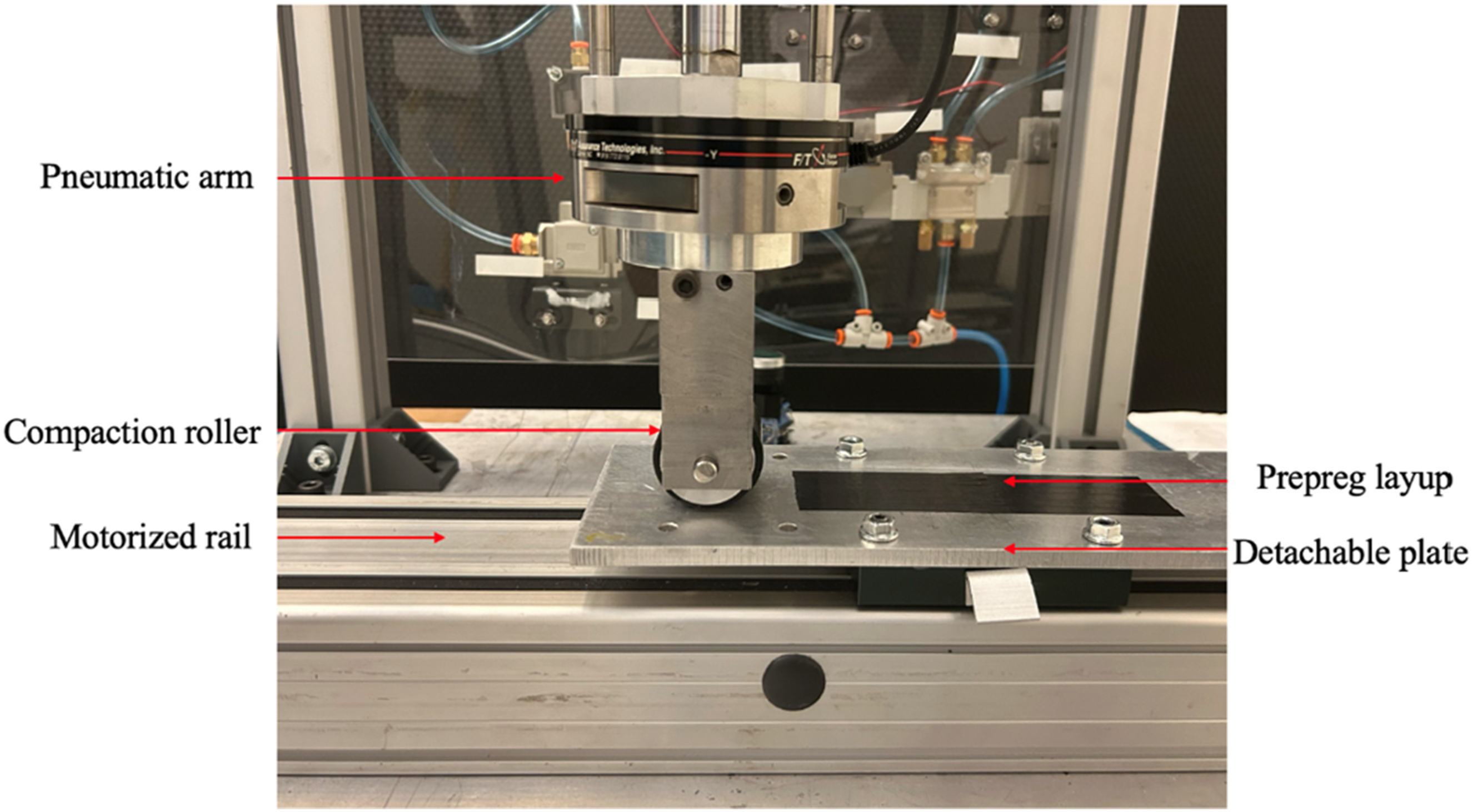
Evaluating prepreg bonding quality at uncured stage
Uncured prepreg tows bond when compaction pressure presses the layers into close contact, while heat reduces resin viscosity and helps the resin flow at the interface and into the fiber network. In this study, “bonding quality” refers to prepreg bonding (interply adhesion/tack) prior to cure. Improving resin penetration and infusion enhances bonding at uncured stage, which is reflected by a higher interlaminar shear strength. Adequate pressure and temperature also reduce resin-rich regions at the interface between two prepreg layers, leading to stronger bonding in the uncured state.
21
Mechanical tests that can indicate the performance of formed bonding at uncured stage, are limited. Traditional methods such as three-point or four-point bending, which are commonly used to evaluate interlaminar bonding strength in composite materials, are unsuitable because prepregs are flexible at the uncured stage. Since no ASTM standard exists for evaluating the shear strength of prepreg tapes, this study adopted ASTM D5868 for the preparation of single-lap joint (SLJ) specimens, with minor modifications to the dimensions. The specimen configuration is illustrated in Figure 5. As the uncured prepreg matrix itself provides bonding between adherends, no additional adhesive was required. Schematic representation of the single-lap joint (SLJ) test configuration: (a) geometry and dimensions of the SLJ specimen; (b) compaction setup illustrating the overlap region under the roller during AFP layup.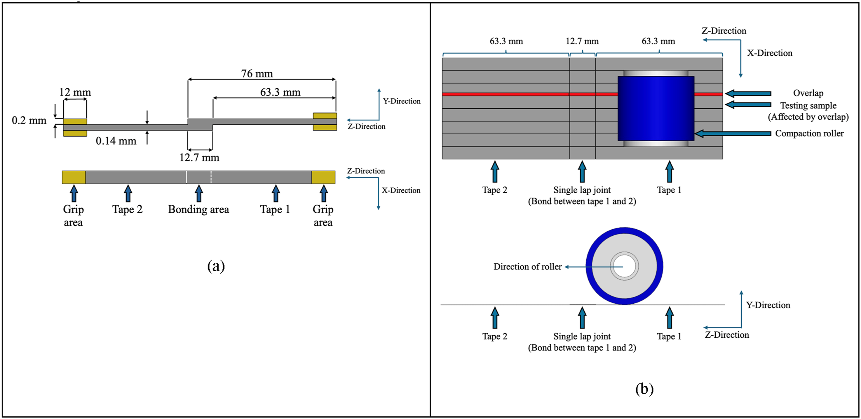
Preparing single lap joint (SLJ) samples
Preparation of the SLJ specimens began by cutting plies of prepreg, which was stored at ambient conditions for 4 h, and manually placing them on an aluminum substrate (detachable plate of the in-house setup shown in Figure 4) with care to maintain dimensional accuracy and avoid pressure on the bonding area. The bonding length was 12.7 mm (0.5 in.), as shown in Figure 5(a) and (b) with a width equal to the width of a prepreg tow (6.3 mm). Layup temperature was controlled using a hot plate, while pressure was applied through the in-house setup, allowing control of process parameters and the use of different compaction rollers. After applying pressure under the desired situation (Desired compaction roller, force, temperature, and feed rate), tabs were affixed to the grip regions of the specimens, and quasi-static single-lap shear tests were performed using a universal testing machine to determine shear strength. The tests were carried out at a constant displacement rate of 1.5 mm/min.
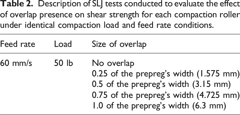
Description of SLJ tests conducted to evaluate the effect of overlap presence on shear strength for each compaction roller under identical compaction load and feed rate conditions.
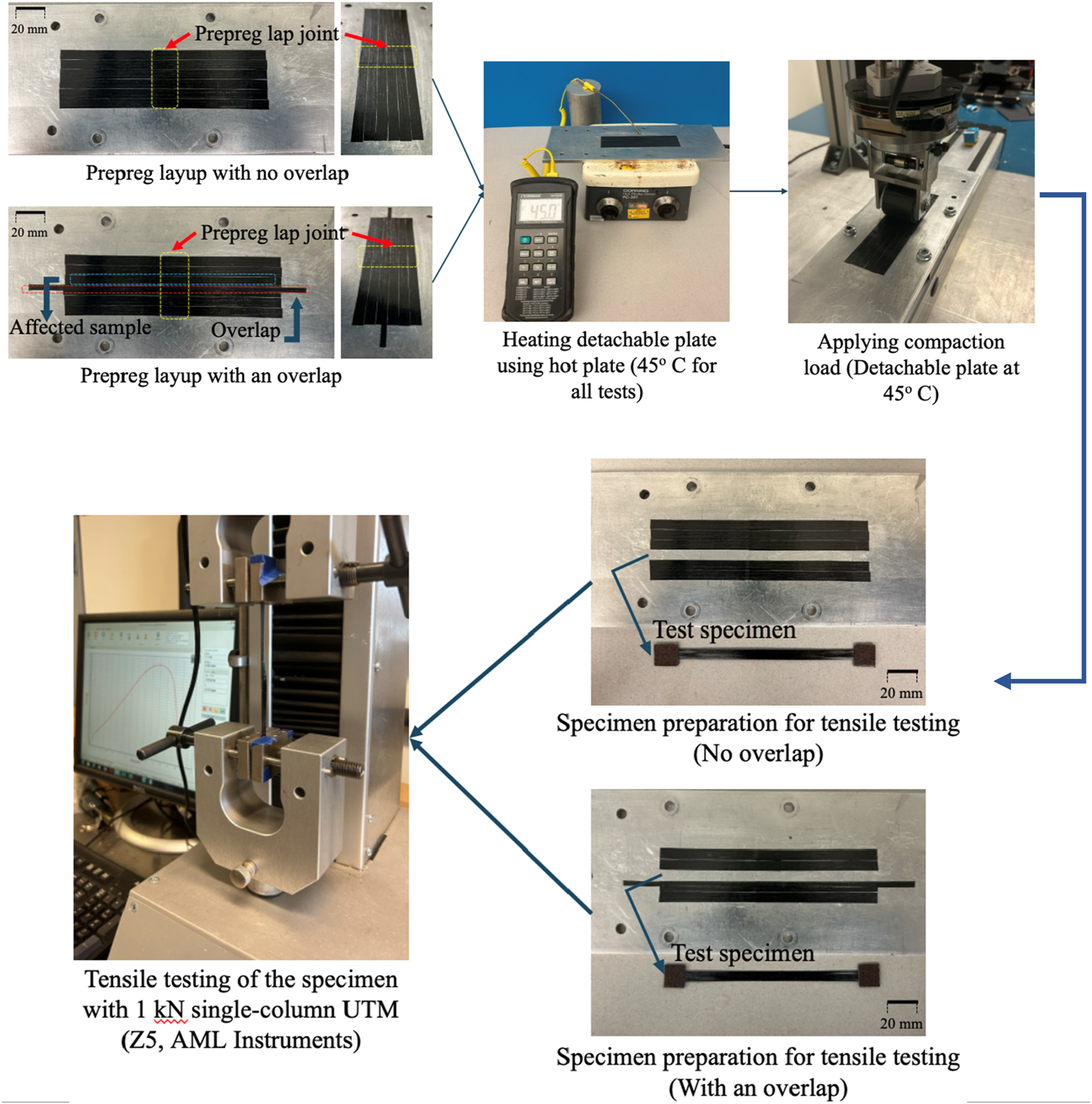
Workflow of the experimental procedure used to fabricate and test SLJ specimens with and without overlaps under conditions simulating the AFP manufacturing process, using a hot plate for heating and an in-house setup for applying compaction pressure.
Results and discussion
Once an overlap aligns parallel to the roller’s movement direction, the adjacent regions experience insufficient compaction pressure, as illustrated in Figure 2. To capture this effect, super low FUJIFILM pressure-sensitive films were used, as shown in Figure 7, to compare a stiff polyurethane roller (PUR 85D-25) with a more compliant candidate roller (PUR 60A-35). A MATLAB code processed the image to enhance clarity and assign pressure values, shown as “Converted pressure film”. The stiff roller (PUR 85D-25) produced a wider affected zone adjacent to the overlap, leading to reduced shear strength and poor bonding at this area. In contrast, increasing the shaft diameter to 35 mm and softening the polyurethane to durometer 60 Shore A significantly narrowed the affected zone while maintaining sufficient compaction pressure, resulting in improved pressure continuity and bonding quality. Comparison of pressure distribution for (a) PUR 85D-25, (b) PUR 85D-25 converted, (c) PUR 60A-35, and (d) PUR 60A-35 converted, in case of a parallel overlap equal to the full prepreg width in the middle, and the compaction roller traversed from left to right at a feed rate of 13 mm/s.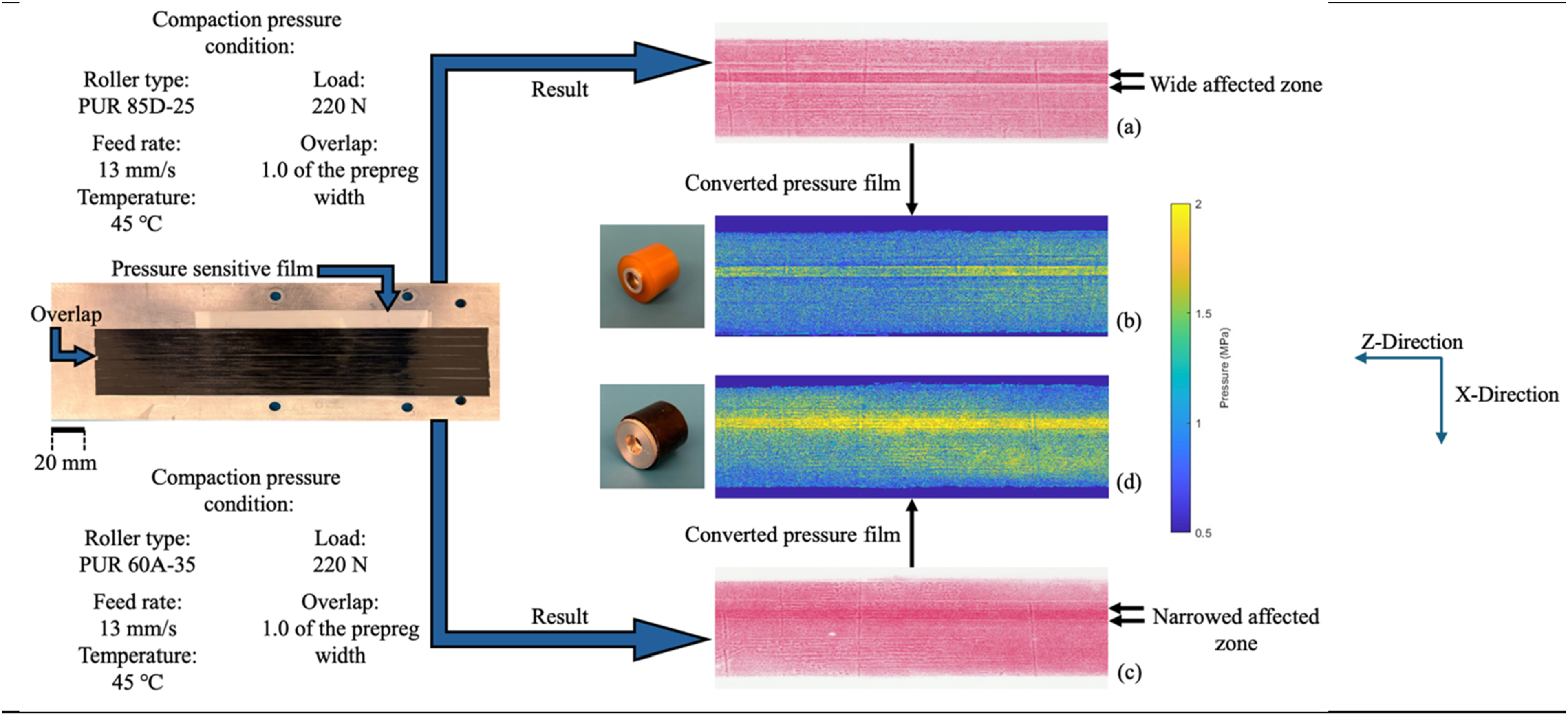
Experimental evaluation of the proposed design approach via SLJ tests
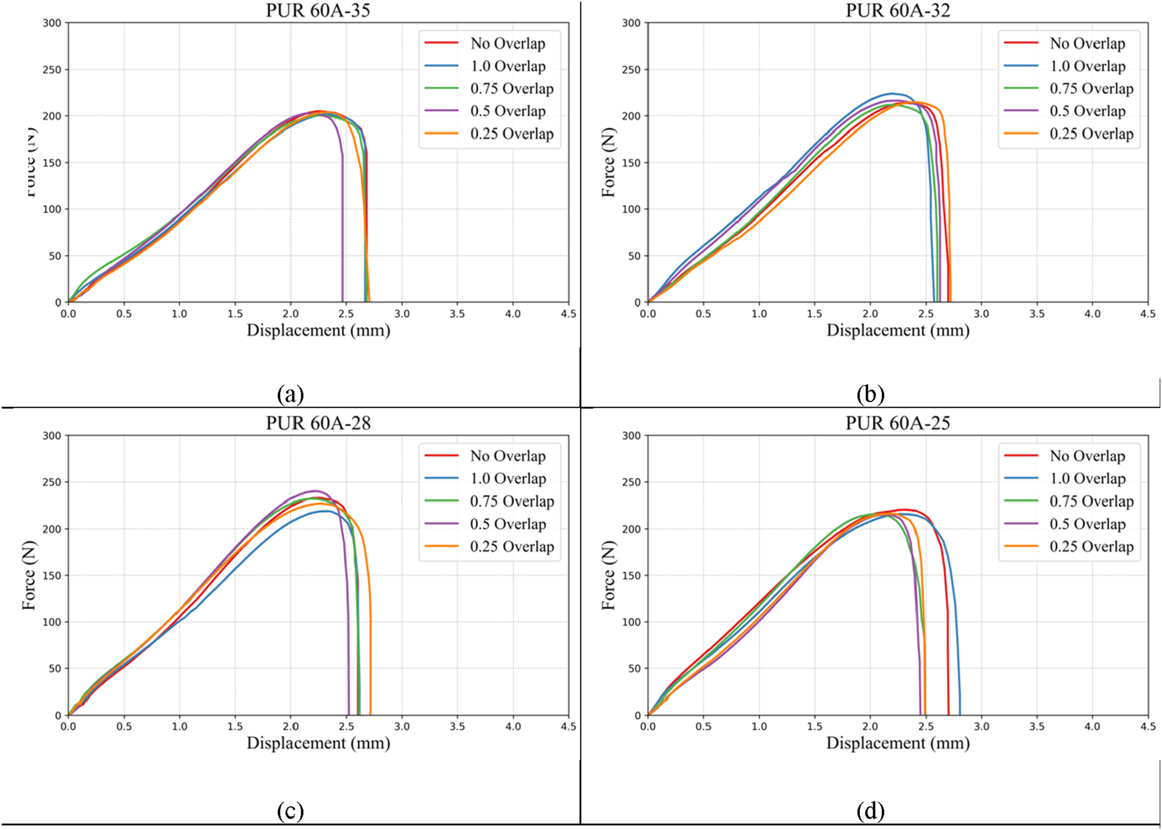
The shear strength of bonds formed using different compaction rollers, both with overlaps of varying widths and without overlaps, is presented in Figure 8 for reference rollers and Figure 9 for the candidate rollers. Single lap joint (SLJ) test results for (a) PUR 60D-25 perforated (b) PUR 60D-25 (c) PUR 85D-25 (d) SSR. Single lap joint (SLJ) test results for (a) PUR 60A-35, (b) PUR 60A-32, (d) PUR 60A-28, (d) PUR 60A-25.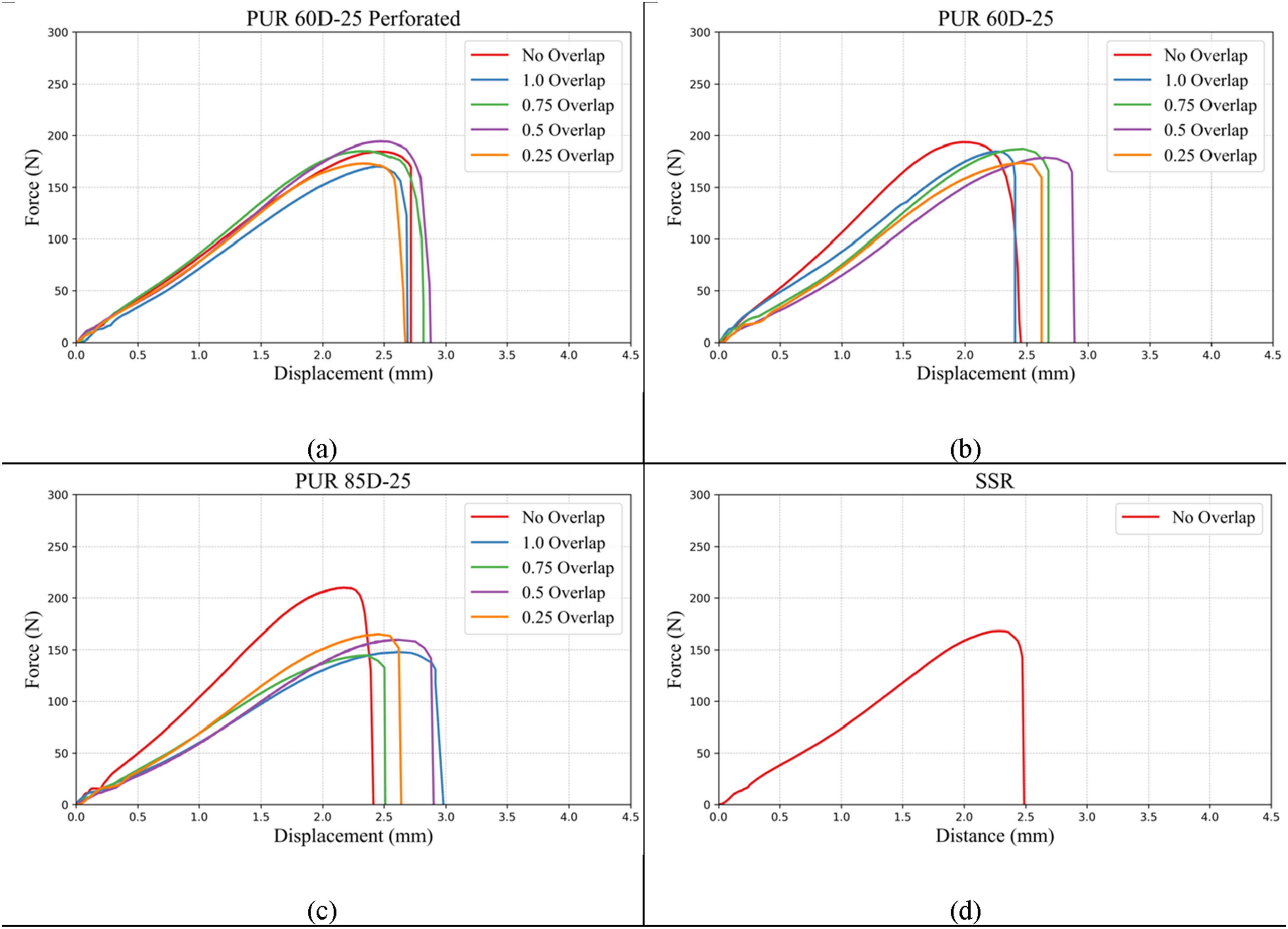
Among the reference rollers, the PUR 60D-25 Perforated offers good formability with narrow affected zone; however, resulting from varying radially hole sizes, it applies inconsistent compaction pressure at different angular positions, resulting in varying shear strength for each sample with inconsistence pressure distribution of this roller be observable in Figure 10(b). The SSR roller, on the other hand, due to its rigid structure, exhibits no formability. It only contacts the highest point on the layup surface. In the presence of an overlap, which is shown in Figure 10(a), this means it rests entirely on top of the overlapped region and fails to apply pressure to the rest of the area. Due to this limitation, preparing SLJ test specimens with overlaps using the SSR roller was not feasible. Pressure distribution of (a) SSR and (b) PUR 60D-25 perforated compaction rollers, in case of a parallel overlap equal to the full prepreg width in the middle, and the compaction roller traversed from left to right at a feed rate of 13 mm/s.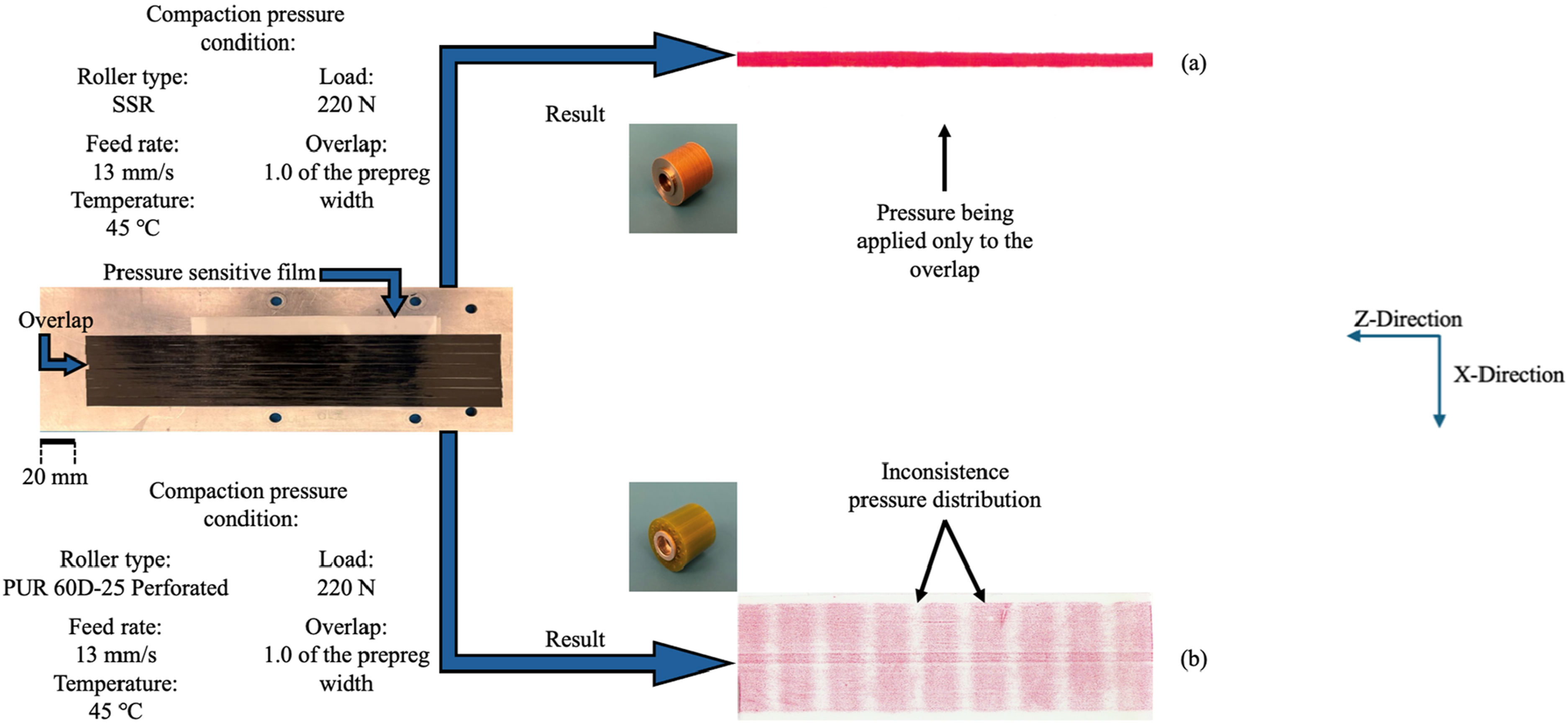
The PUR 60D-25 roller generates a narrow affected zone, indicating that the overlap’s influence on pressure non-uniformity on adjacent tapes is limited. As it can be understood from SLJ tests, shear strength of overlap affected samples does not decrease significantly. Because of the soft polyurethane, this roller produces lower compaction pressure with a larger contact width. According to, 26 under a compaction load of 222.4 N, its peak pressure is 0.85 MPa, with a 10.1 mm contact width and an average pressure of 0.73 MPa.
In contrast, the PUR 85D-25 roller, as illustrated in Figure 7(a) and (b), shows a wider affected zone. Although in the “No overlap” configuration this stiffer roller forms stronger bonding due to its higher pressure (2.05 MPa peak, 1.61 MPa average, and 4.6 mm contact width at 222.4 N),
26
its limitation is visible in Figure 8(c), where the shear strength of samples affected by an overlap is noticeably lower than “No overlap” samples. As illustrated in Figure 11(a), samples manufactured by this roller and affected by an overlap fail earlier on the side that was adjacent to the overlap, confirming weak bonding in the affected zone and explaining their reduced shear strength compared to unaffected specimens. Comparison of compaction pressure, contact width, and converted pressure distributions for (a) PUR 60A-35, (b) PUR 60A-32, (c) PUR 60A-28, and (d) PUR 60A-25, each subjected to an applied load of 220 N.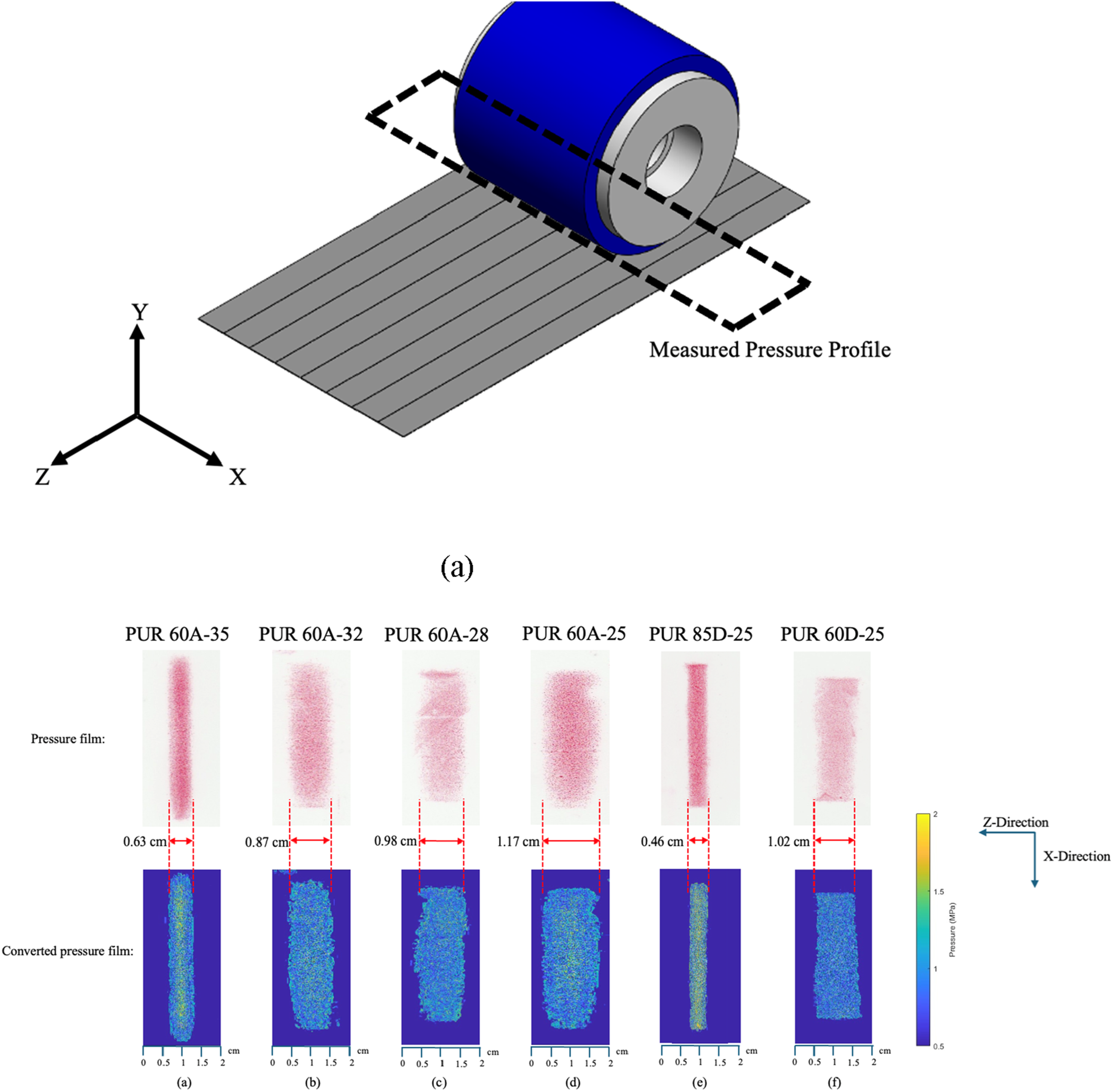
Compaction rollers developed under the design approach proposed in this study perform effectively in the presence of overlaps. For PUR 60A-35 (Figure 9(a)) and PUR 60A-32 (Figure 9(b)), the SLJ tensile test results indicate relatively consistent shear strength values regardless of overlap presence, reflecting stable compaction pressure and uniform bonding performance. When comparing PUR 60A-25 and PUR 60D-25, the softer Shore A polyurethane exhibited better formability and reduced sensitivity to overlap. Moreover, contact time is one of the parameters that can influence the shear strength of the bonding, which itself is a parameter related to the contact width of the roller under the known load and the feed rate, which can be extracted from equation (2):
Where CW is contact width and FR is the feed rate. Between PUR 60D-25 and PUR 60A-25, the contact width increases from 10.1 mm to 11.7 mm (Figure 11(d)) respectively, resulting in longer contact time and stronger bonding formation.
Effect of compaction roller on failure propagation in SLJ specimens
The influence of overlap on failure behavior during SLJ tests can be observed depending on the type of compaction roller used. Figure 12 presents the failure progression of an SLJ specimen subjected to an overlap. Propagation of bonding failure in SLJ specimens adjacent to a 0.5 tow-width overlap under a compaction load of 220 N, feed rate of 60 mm/s, and temperature of 45°C: (a) using a PUR 85D roller, and (b) using a PUR 60A-35 roller.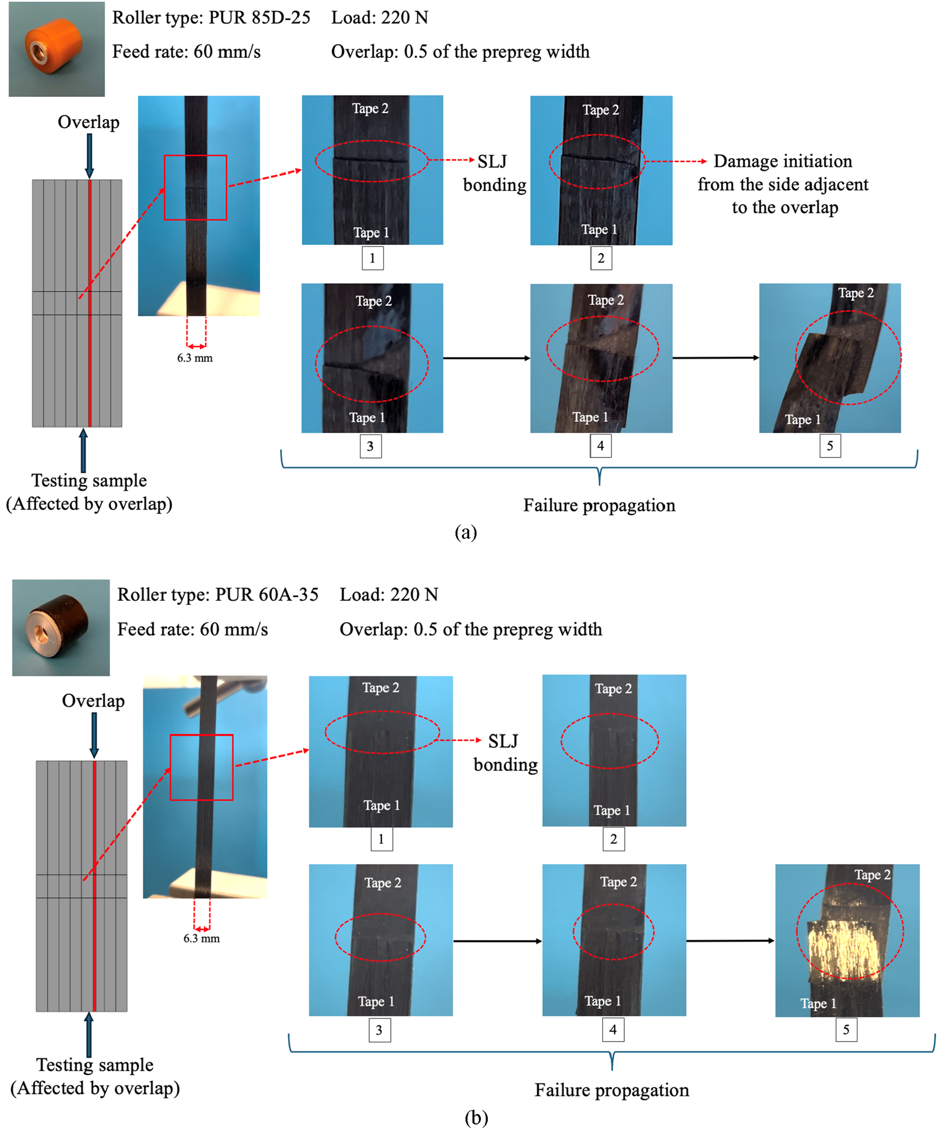
When the PUR 85D-25 roller was utilized (Figure 12(a)), a distinct region near the overlap (affected zone, shown in Figure 7(a)) experienced insufficient compaction pressure. This affected zone receives insufficient compaction pressure. Hence, bonding’s damage initiation and failure propagation occur from the side that was adjacent to the overlap. In contrast, the result obtained with the PUR 60A-35 roller (Figure 12(b)) exhibits a more uniform failure pattern across the tape width, indicating enhanced bonding consistency and a more consistent compaction pressure distribution, even in the presence of an overlap.
Microscopic examination of bonding interface
Microscopic examinations were performed to compare the bonding interface between prepreg plies and to visualize the extent of resin that had been infused into the fiber network. Careful manual layup and precise alignment of prepreg tows were ensured to maintain consistency among samples. Three repeats were prepared for each configuration. To minimize handling-induced errors, specimens were held only from one side before molding, and the handled section was excluded from microscopic analysis, as pressure during handling could have affected the bonding.
Parallel overlap configuration
For parallel overlap, specimens prepared using three polyurethane rollers (PUR 60A-25, PUR 60A-35, and PUR 85D-25) were compared. The compaction process was carried out under a constant feed rate of 60 mm/s, an applied load of 220 N, and a temperature of 45°C. Samples affected by an overlap were located adjacent to an overlap with a width equal to the full prepreg tow width. The workflow for preparing microscopic samples is shown in Figure 13. For specimens affected by an overlap, images were taken from the side adjacent to the overlap, and polishing had been done carefully to expose the correct section without material loss. Workflow of the experimental procedure for preparing microscopic samples. (a) Schematic of the two ply prepreg layout and showing the overlap region. (b) Definition of observation planes A (side affected by the overlap) and B (side unaffected by the overlap). (c–d) Mounting the specimen on the clipper and covering it with epoxy. (e–f) Multi level polishing and final preparation for microscopic observation.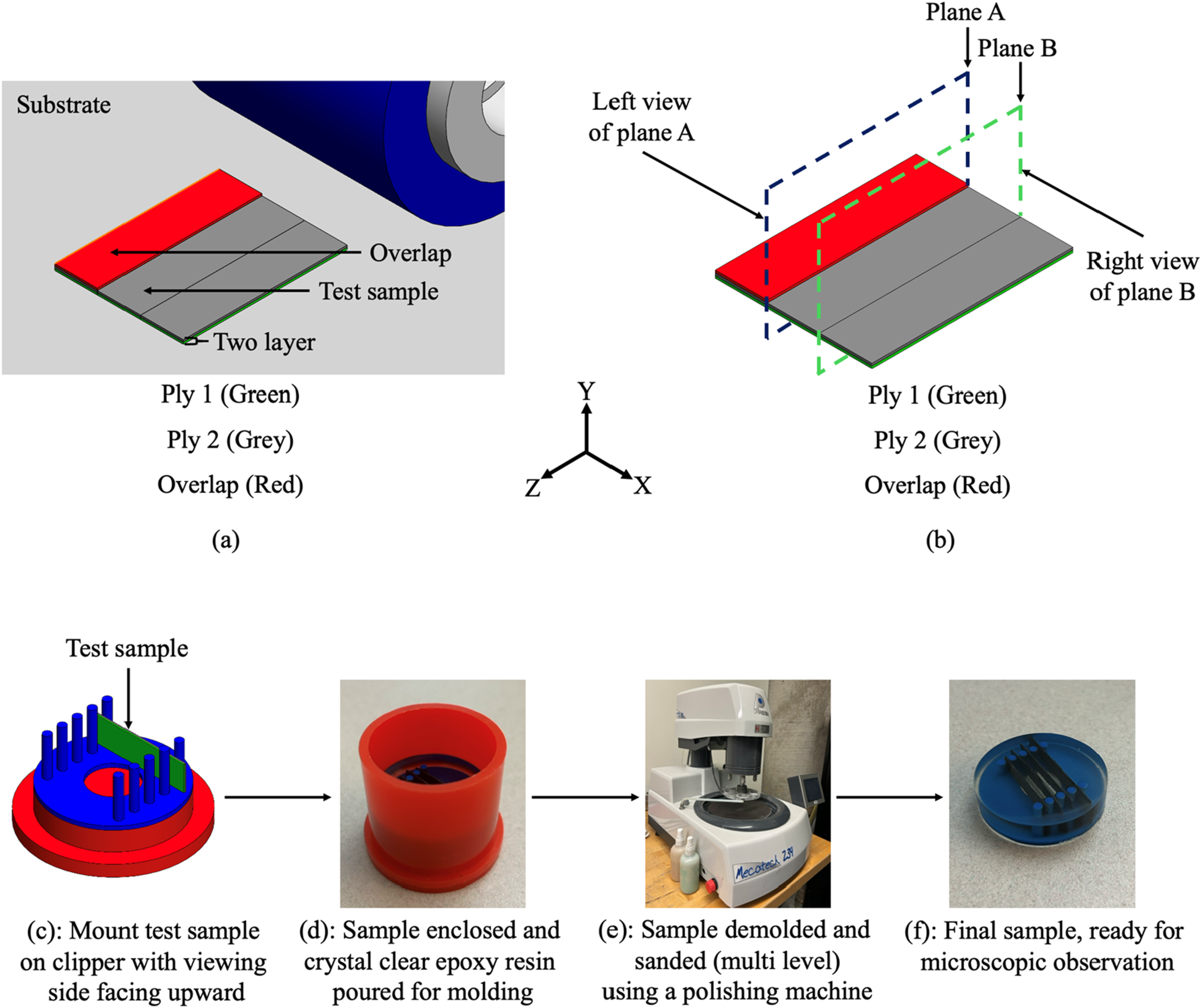
Microscopic pictures shown in Figure 14 indicate how infusion of the resin into the fiber network can vary. PUR 85D-25 affected the most from the overlap presence, and bonding thickness increased significantly from 15 µm (Figure 14(b)) to 36 µm (Figure 14(a)). For PUR 60A-25, this increase is not as significant, and it goes from 16 µm (Figure 14(d)) to 24 µm (Figure 15(c)). For PUR 60A-35, the bonding thickness experiences a minor increase of 16 µm to 18 µm. This is an indication of the superior performance of PUR 60A-35 in reducing the influence of overlap on adjacent tapes. (a) PUR 85D-25 with an adjacent parallel overlap (b) PUR 85D-25 with no overlap (c) PUR 60A-25 with an adjacent parallel overlap (d) PUR 60A-25 with no overlap (e) PUR 60A-35 with an adjacent parallel overlap (f) PUR 60A-35 with no overlap. Workflow of the experimental procedure for preparing microscopic samples. (a) Schematic of the two ply prepreg layout and showing the overlap region. (b) Definition of observation planes A (c–d) Mounting the specimen on the clipper and covering it with epoxy. (e–f) Multi level polishing and final preparation for microscopic observation.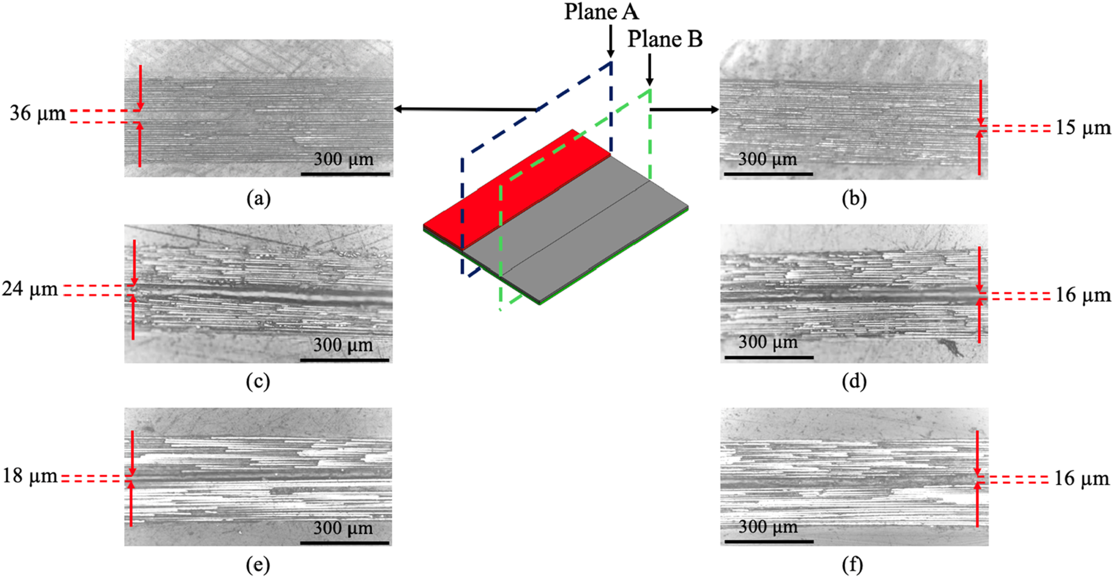
Perpendicular overlap configuration
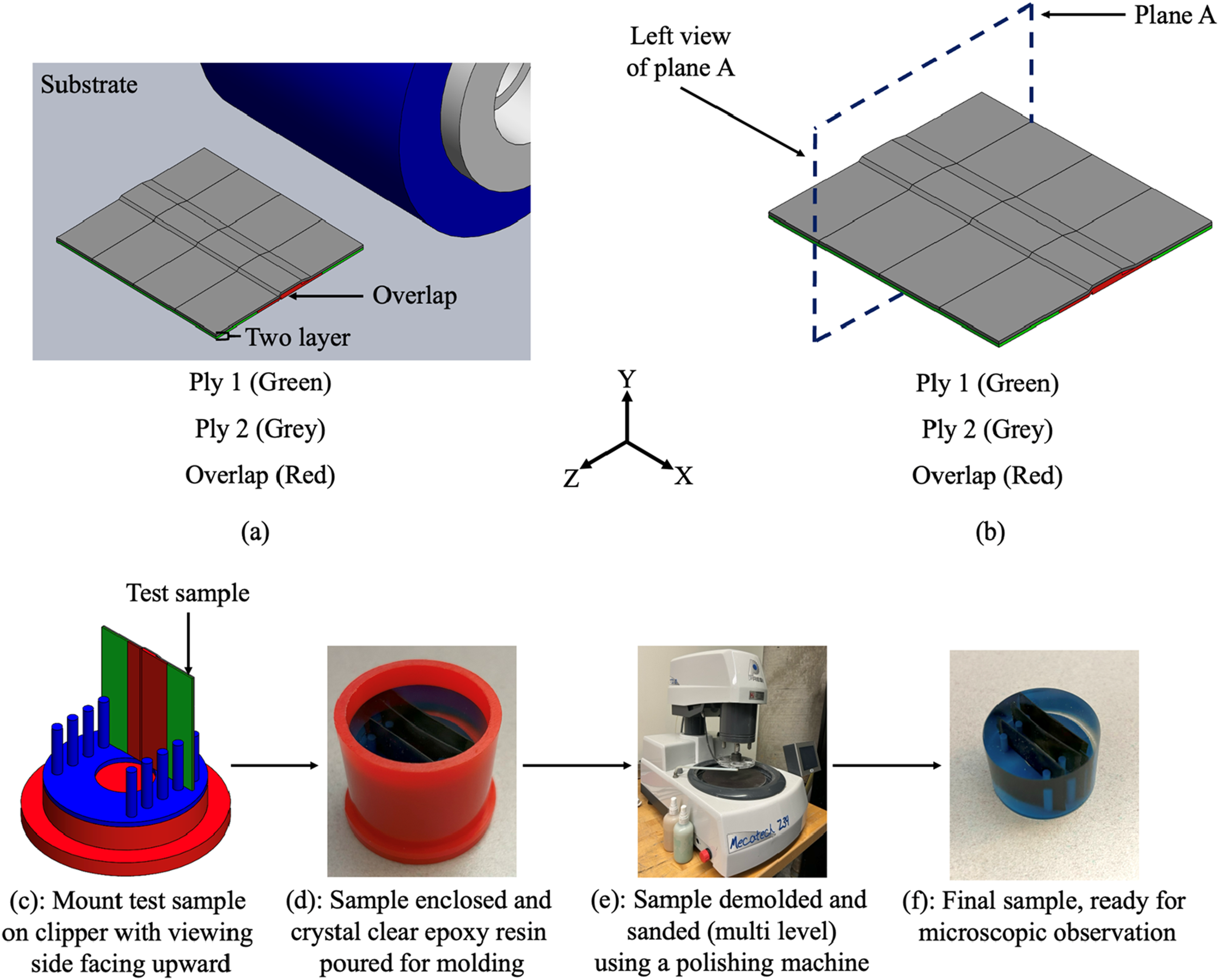
Perpendicular overlaps occur when an overlap has already formed in a lower layer, and the AFP machine proceeds to place an upper layer at a 90°fiber orientation relative to the one beneath it. To capture microscopic pictures, specimens prepared using four polyurethane rollers (PUR 60A-25, PUR 60A-32, PUR 60A-35, and PUR 85D-25). The compaction process was carried out under a constant feed rate of 60 mm/s, an applied load of 220 N, and a temperature of 45°C. The overlap width in this series of tests was equal to half of the prepreg tow width. The workflow for preparing microscopic samples is shown in Figure 15.
In the case of perpendicular overlaps, the prepreg tow fails to achieve proper bonding with the underlying layer within the affected zone, resulting in bridging. Ideal situation is to shorten the bridging as much as possible, since the section of the tow that has no sufficient bonding with its beneath layer, can be an initiation region for further defects such as fiber waviness and tape folding. In Figure 16, line AB represent the affected zone. The candidate rollers demonstrate notable improvements: while the PUR 85D-25 roller failed to form bonding for up to 1.1 mm before the overlap (Figure 16(a)), this distance decreased to 0.63 mm with PUR 60A-25 (Figure 16(b)), 0.42 mm with PUR 60A-32 (Figure 16(c)), and 0.36 mm with PUR 60A-35 (Figure 16(d)). These results confirm that increasing the shaft diameter enhances the roller’s performance in managing perpendicular overlaps. Bonding formed adjacent to a perpendicular overlap with a width equal to 0.5 times the prepreg tow width, using: (a) PUR 85D-25, (b) PUR 60A-25, (c) PUR 60A-32, and (d) PUR 60A-35.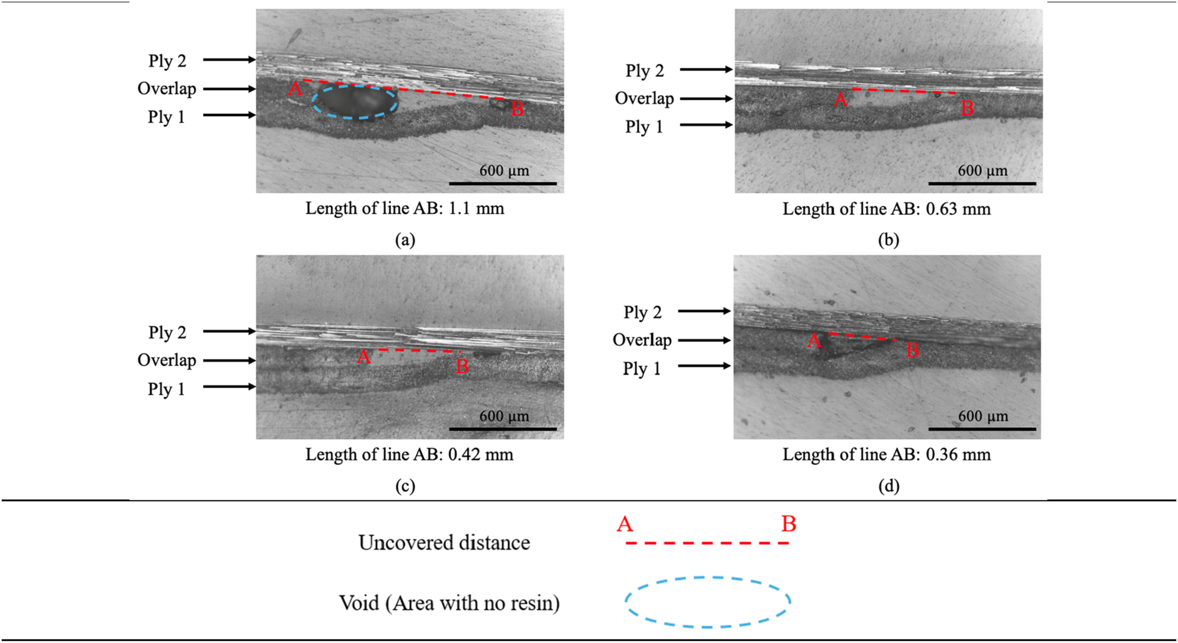
Finite element method analysis
Material properties.
The substrate plate was modeled as an aluminum surface to represent the metallic tooling used in AFP. Since the primary objective of the simulation was to evaluate the pressure distribution of each roller, this simplification was considered appropriate. As illustrated in Figure 17, a vertical load of 220 N was applied through a reference point (RP) which is kinematically coupled to the inner surface of the roller shaft. The RP was constrained in all degrees of freedom except for vertical translation (Y-direction), making it possible for controlled downward displacement. A frictionless hard contact interaction was defined between the roller and the plate. The compaction roller, due to its complex geometry and large deformation, was meshed using C3D10 quadratic tetrahedral elements, whereas the plate was meshed with C3D8R linear brick elements due to its simpler geometry. The plate’s bottom surface was fully constrained to prevent any motion. FEM model of the PUR 60A-35 and a surface with an overlap of 0.5 of the prepreg’s width. The simulation is used to capture the pressure distribution under a 220 N load, applied to the reference point (RP) as indicated by arrow F.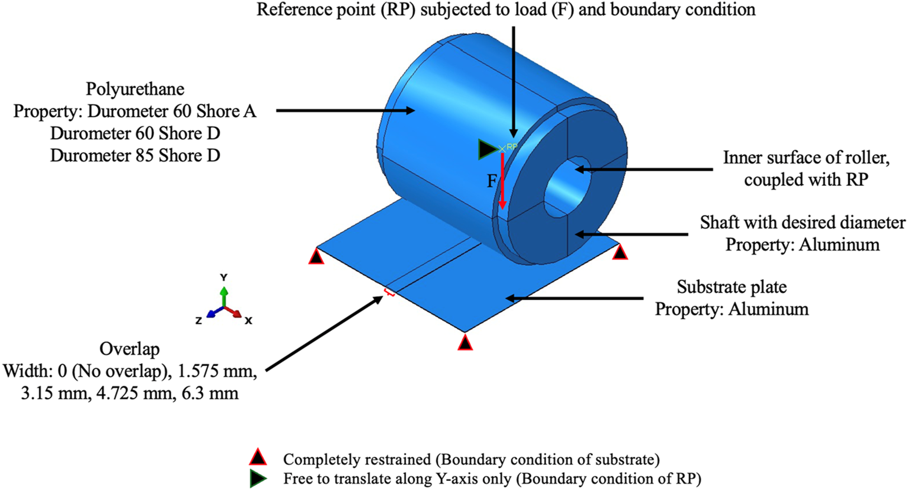
The model shown in Figure 17 corresponds to the PUR 60A-35 and an overlap equal to half of the prepreg’s width; however, equivalent models were generated for all roller types, overlap levels, and the no overlap case.
Mesh study
For choosing a mesh size that balances efficiency and resolution, a mesh study had been conducted. This study performed for PUR 60A-35 since its contact results showed the highest stress peaks near the overlap edges among the reference rollers. Mesh convergence study was conducted on two configurations: a model without overlaps and a model with a 1.0 overlap. For the model with an overlap, convergence was evaluated at the overlap edges and in adjacent area of the overlap.
As shown in Figure 18(a) and (b), reducing the roller mesh size from 0.8 mm to 0.6 mm led to negligible improvement in resolution while it required huge increase in computational cost. Therefore, for overlap models, a mesh size of 0.1 mm was used for the plate and 0.8 mm for the roller. For models with no overlap, where mesh sensitivity is less critical (Figure 18(c)), 0.2 mm and 0.8 mm were selected for the plate and roller, respectively. Mesh convergence study for (a) areas adjacent to the overlap, (b) overlap edges, and (c) model without overlap.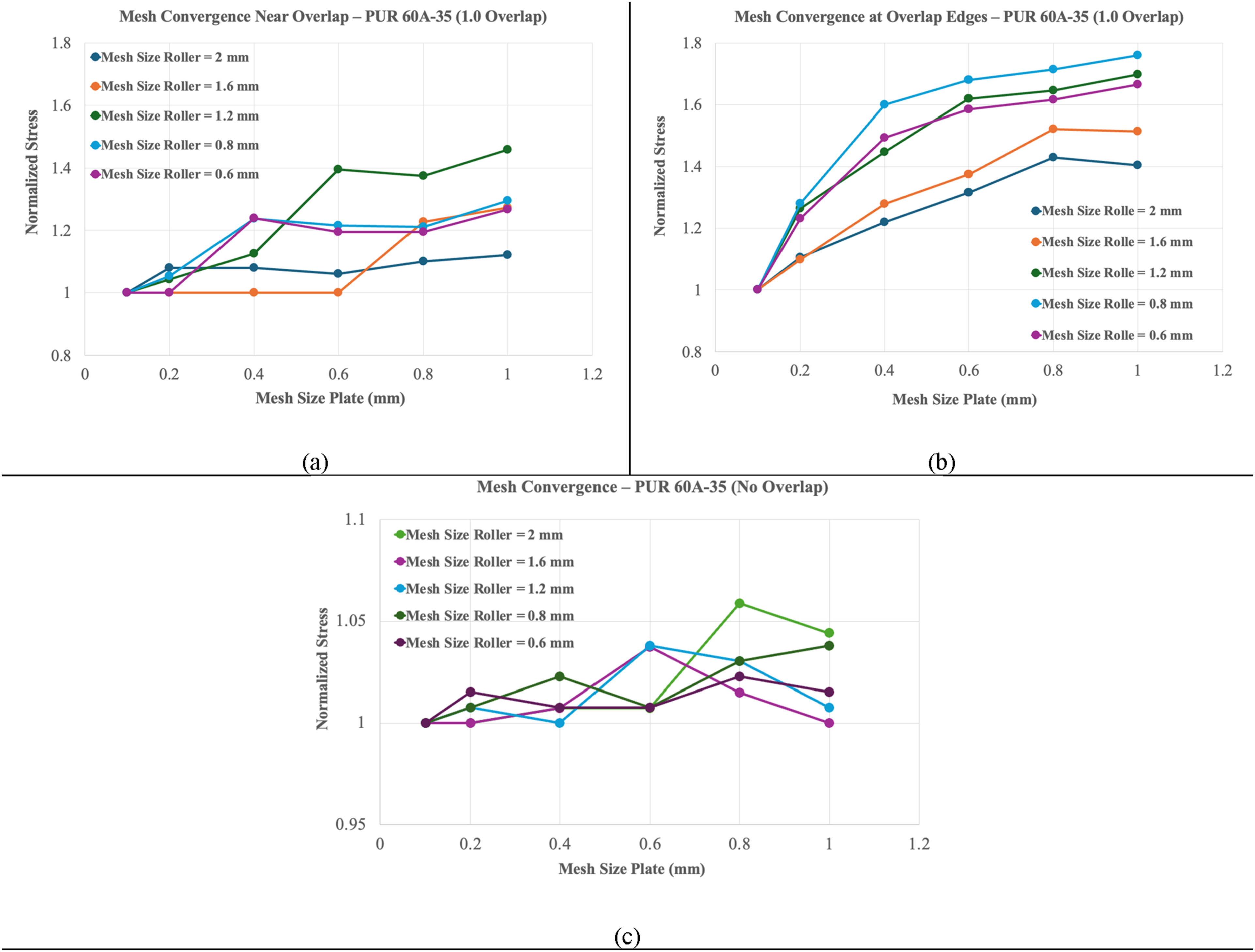
Validation of the finite element method
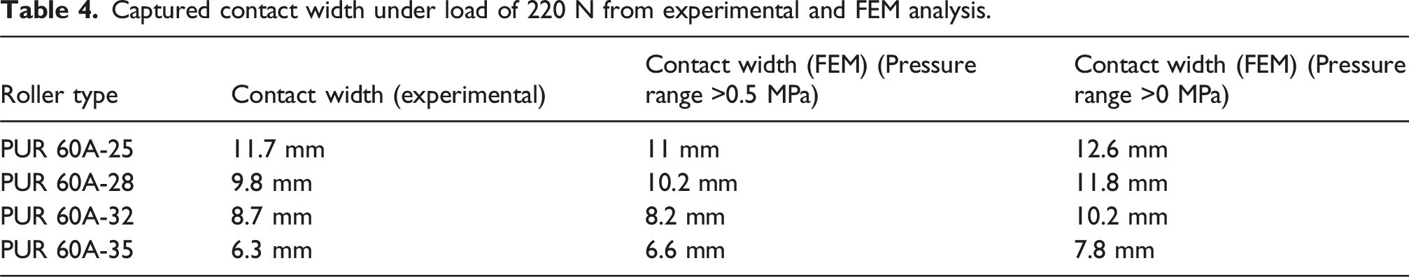
Pressure films only detect pressures between 0.5 MPa and 2.5 MPa, limiting accuracy across a wide pressure range. To validate FEM results with pressure films, the contact width from FEM was extracted in two ways: (1) the width of the region where pressure exceeded 0.5 MPa, and (2) the width of the full contact width, including pressure zones with pressure lower than 0.5 MPa.
Captured contact width under load of 220 N from experimental and FEM analysis.
Capturing pressure distribution without the presence of an overlap
Figure 19 presents the pressure distribution of candidate rollers under a 220 N load, obtained from FE analysis. The coordinate system used in the analysis is illustrated in Figure 17. Accordingly, FEM pressure maps for candidate rollers at 220 N (no overlap): (a) PUR60A-25, (b) PUR60A-28, (c) PUR60A-32, (d) PUR60A-35.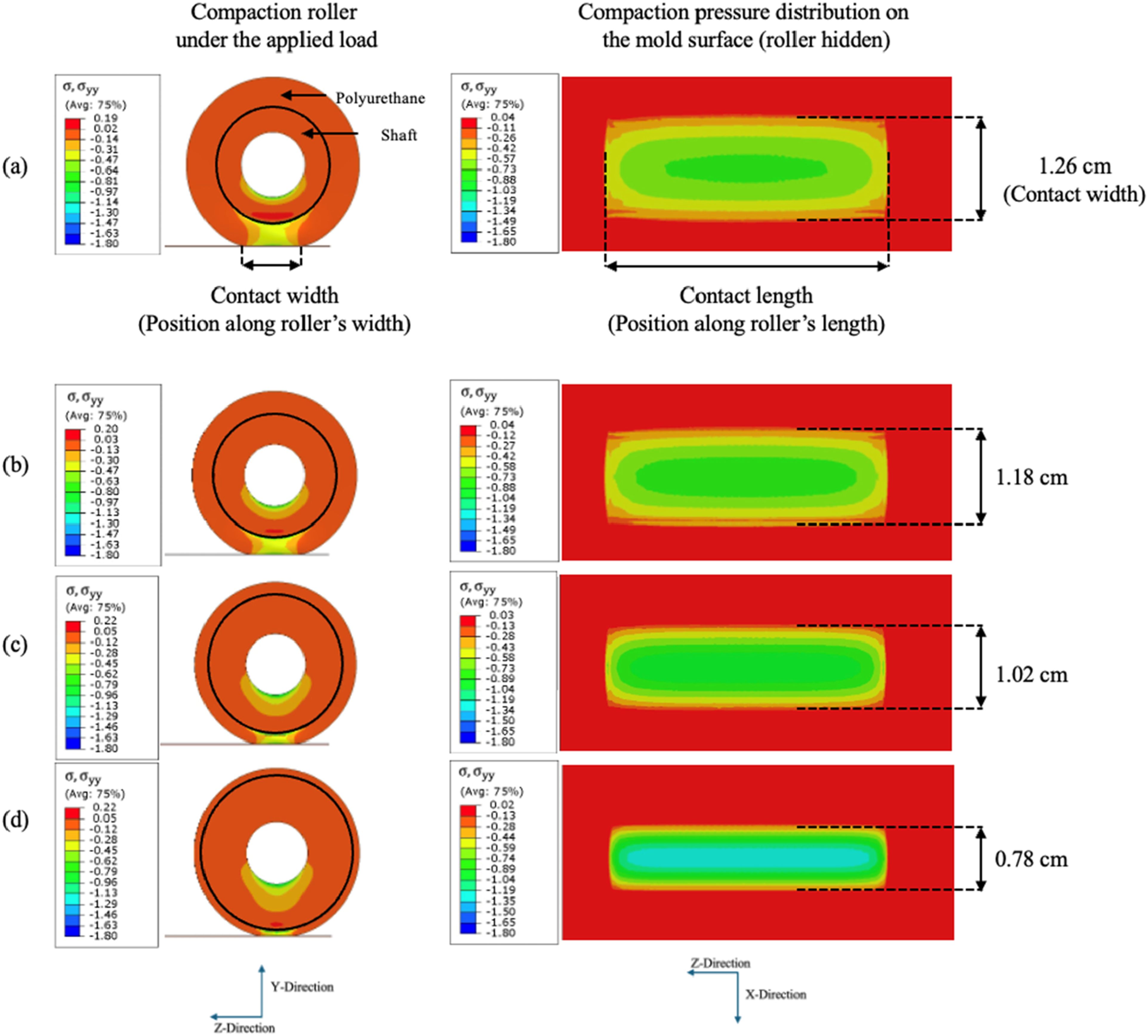
Figure 20(b) shows the distribution across the roller width, and Figure 20(c) along the roller length for all candidate rollers and reference rollers (PUR 60D-25 and PUR 85D-25). As observed, increasing the polyurethane stiffness from PUR 60D-25 to PUR 85D-25 results in a significant reduction in contact width and an increase in maximum compaction pressure with a change from approximately 0.95 MPa to 2 MPa. However, in the case of PUR 85D-25, peak pressure happens briefly and this pressure drops sharply since the contact width is too small (4.6 mm). In contrast, candidate rollers’ design allows for achieving peak pressures of 1.3 MPa for PUR 60A-35, while preserving a wide contact area. Pressure extraction paths and corresponding pressure profiles under the no-overlap condition: (a) schematic defining the extraction paths along the roller width and length; (b) pressure distribution along the roller’s width; (c) pressure distribution along the roller’s length for all reference and candidate rollers.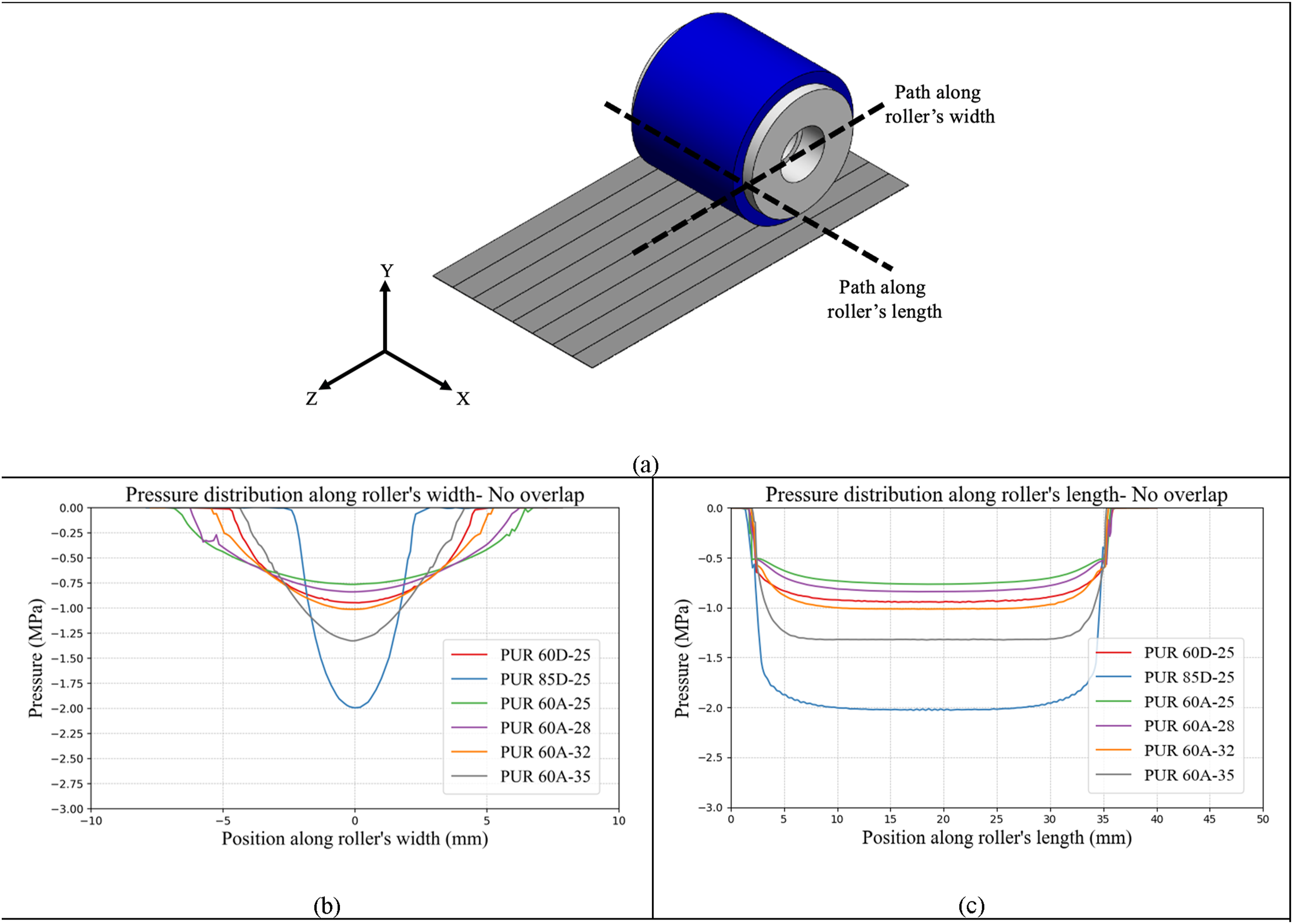
Capturing pressure distribution with the presence of an overlap
Utilizing the FEM analysis for a surface with an overlap, it is possible to capture the pressure distribution of the compaction roller once it is facing an overlap. Accordingly, the pressure profiles in the presence of an overlap were extracted along the path defined in Figure 21. Overlap location and pressure-extraction path along the roller length.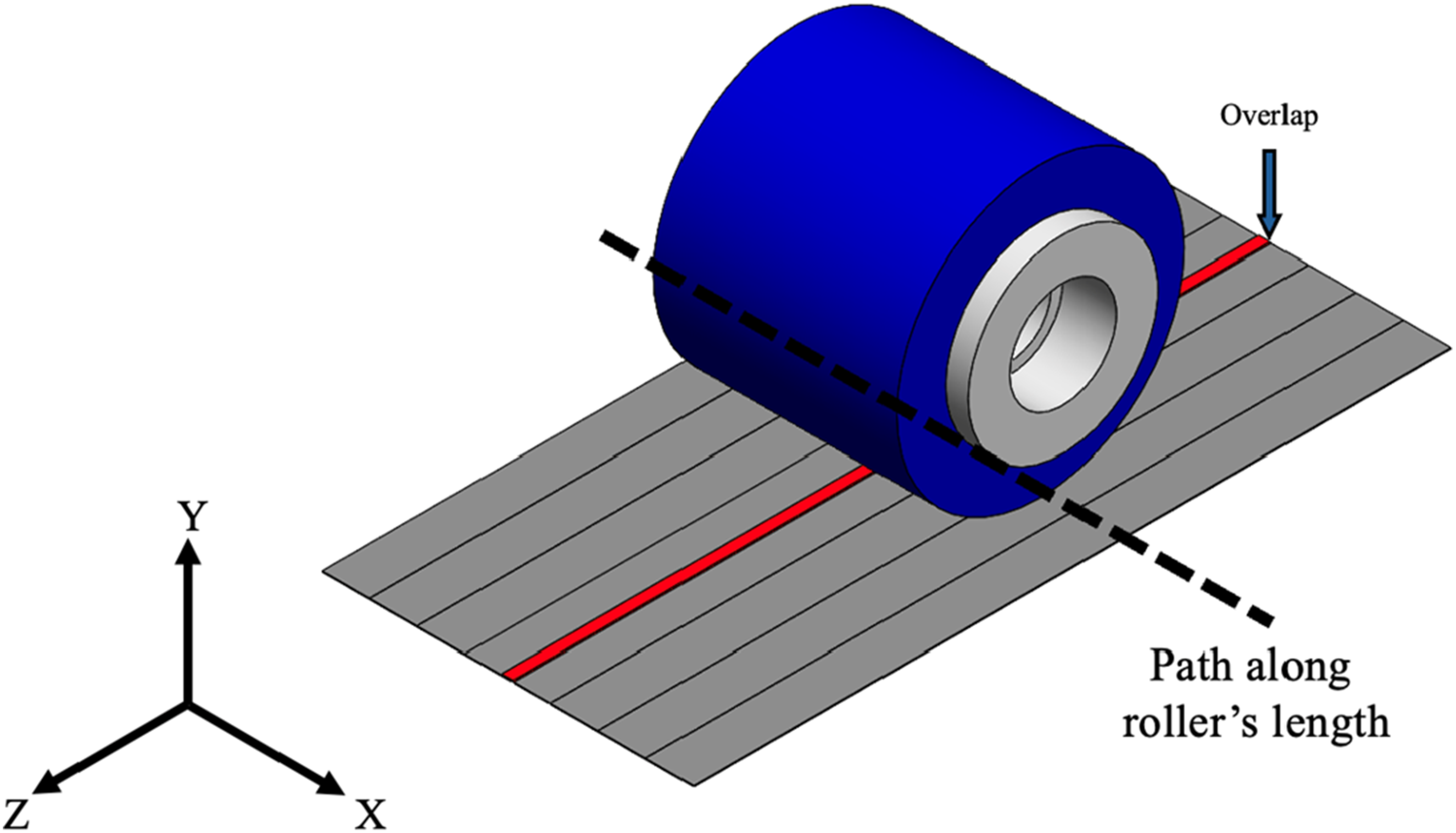
As shown in Figure 22, PUR 85D-25 exhibits significantly higher peaks at overlap edges, and additionally, leaves larger affected zone adjacent to the overlap, whereas PUR 60D-25 is more quick returning to its normal pressure. Pressure distribution of reference rollers in the presence of (a) 0.25, (b) 0.5, (c) 0.75, and (d) 1.0 overlaps.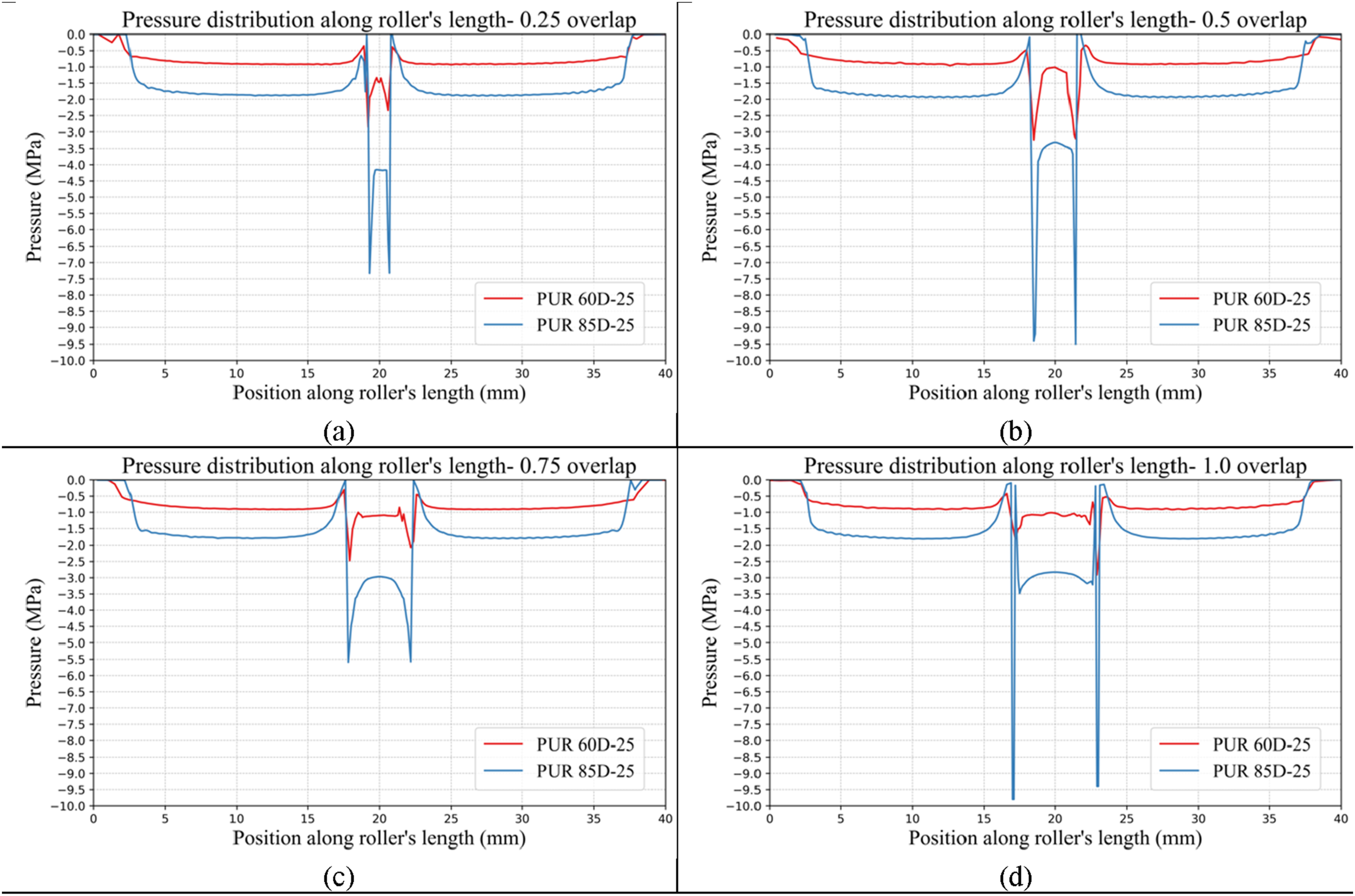
For candidate rollers (Figure 23), the pressure peaks at the edges of the overlap are noticeably reduced, even in the case of PUR 60A-35, which has the largest shaft diameter. Additionally, all these rollers exhibit smaller affected zones compared to PUR 85D-25, indicating that their influence by the presence of an overlap is much lower than reference rollers, and they leave narrower affected zones. This highlights the effectiveness of their design approach in maintaining uniform pressure distribution despite surface irregularities and provides both a proper compaction pressure and formability at the same time. Pressure distribution of candidate rollers in the presence of (a) 0.25, (b) 0.5, (c) 0.75, and (d) 1.0 overlaps.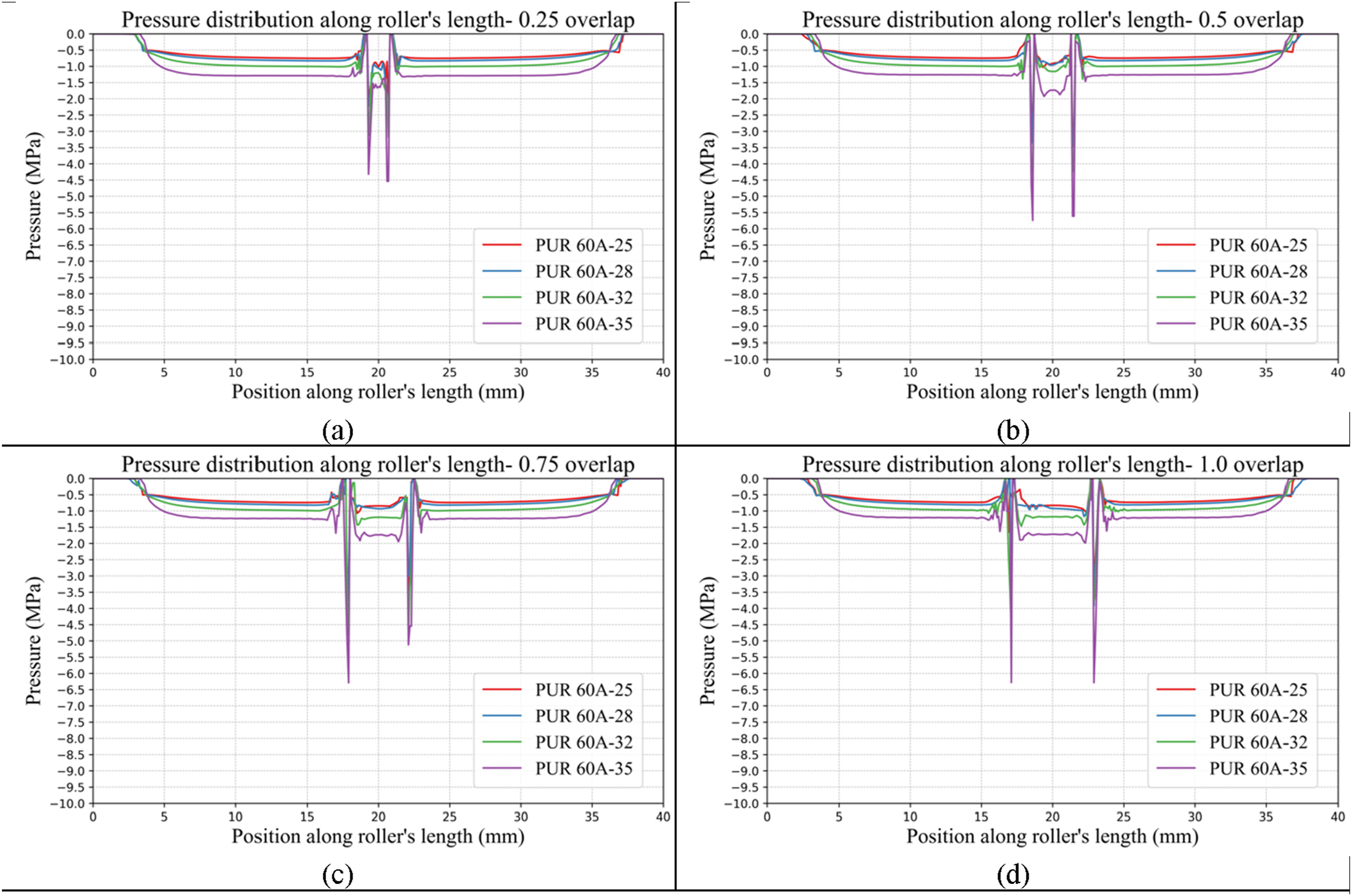
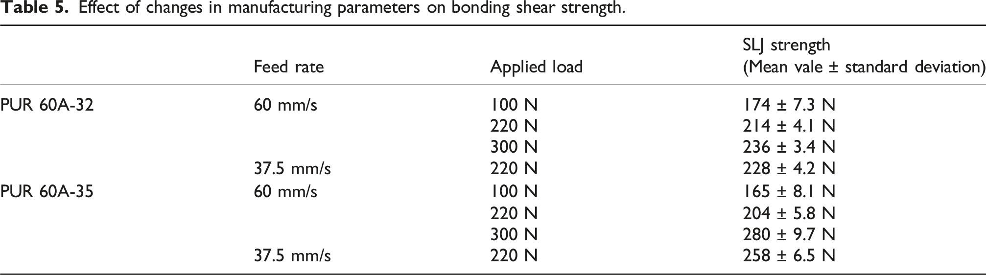
Sensitivity of candidate rollers to process parameters variation
Effect of changes in manufacturing parameters on bonding shear strength.
Conclusion
This study investigated the influence of prepreg tow overlap defects on the interlaminar bonding of the adjacent tows at uncured stage and the compaction pressure distribution in thermoset AFP, by comparing reference rollers with rollers developed using the proposed design approach (candidate rollers). Based on a combination of experimental testing and finite element (FE) modeling, overlap formation was shown to disturb the compaction pressure and reduce bonding consistency, with the size and severity of the affected zone being strongly dependent on roller type. Among the reference rollers, the stiffer polyurethane roller (PUR 85D-25) exhibited the highest sensitivity to overlaps, while the rigid stainless-steel roller (SSR) fully lost its ability to apply pressure to regions outside the overlap. The FE results confirmed these trends, showing that PUR 85D-25 produces sharp pressure peaks at the overlap edges and a larger low pressure region adjacent to the overlap, indicating reduced formability and increasing the risk of poor bonding and defect propagation. Compared with PUR 85D-25, PUR 60D-25 showed improved formability over overlaps; however, it generated lower peak compaction pressure and therefore could not achieve bonding strength comparable to PUR 85D-25 under ideal (no-overlap) conditions. The perforated PUR 60D-25 also conformed well over surface irregularities, but its non-uniform perforation architecture caused variations in stiffness radially, leading to an uneven pressure distribution, which is undesirable for consistent bonding.
To address these limitations, a new roller concept was implemented that combines a low stiffness polyurethane outer layer with varying thicknesses supported by shafts of different diameters, while maintaining the fixed total roller diameter of 38 mm. Because the optimal shaft-to-polyurethane thickness ratio was not known at the beginning, four candidate rollers with shaft diameters of 25, 28, 32, and 35 mm were manufactured and evaluated experimentally. Among them, PUR 60A-32 provided the most favorable balance between compaction pressure, contact time, and formability. It maintained a more uniform pressure distribution across overlaps and showed a smooth, limited sensitivity to changes in key process parameters (feed rate and applied load), which is important for maintaining consistent bonding during manufacturing. Microscopy and SLJ shear testing further supported the improved performance of the proposed design, demonstrating that the overlap influence can be localized, and the risk of further defect formation can be reduced. Overall, while overlaps inherently introduce pressure non-uniformity and can degrade bonding, the proposed roller design approach reduces this non-uniformity to a level where the bonding quality of adjacent tows can be maintained even when an overlap is present next to it. Given that overlap formation is often unavoidable in AFP, robust roller designs should perform reliably under both ideal conditions and in the presence of overlaps; within the investigated designs, PUR 60A-32 best satisfied these requirements by providing uniform pressure delivery, adequate formability, and stable behavior under process variations. This improved contact also helps reduce local tow distortion near the overlap (such as bridging), which lowers the chance of further defects forming during deposition. A key takeaway is that overlap sensitivity is mainly controlled by the roller’s core–shell stiffness balance (metal shaft vs polyurethane thickness). A larger shaft makes the roller stiffer and helps it apply more pressure, while a soft polyurethane layer helps the roller to maintain an adequate contact even in the presence of an overlap. This combination also reduces poor bonding near the overlap and lowers the chance of defects growing during layup at those regions.
Footnotes
Acknowledgments
The authors gratefully acknowledge financial support from the Natural Science and Engineering Research Council of Canada (NSERC) through Discovery Grant.
Author contributions
Amir Hafez Yas: Writing- original draft, Software, Methodology, Investigation, Formal analysis. Mehdi Hojjati: Writing-review and editing, Validation, Supervision, Project administration, Funding acquisition, Conceptualization.
Funding
The authors disclosed receipt of the following financial support for the research, authorship, and/or publication of this article: This work was supported by the Natural Sciences and Engineering Research Council of Canada (NSERC).
Declaration of conflicting interests
The authors declared no potential conflicts of interest with respect to the research, authorship, and/or publication of this article.
Data Availability Statement
Data sharing not applicable to this article as no datasets were generated or analyzed during the current study.