
Abstract
Background:
Ankle foot orthoses are external medical devices applied around the ankle joint area to provide stability to patients with neurological, muscular, and/or anatomical disabilities, with the aim of restoring a more natural gait pattern.
Study design:
This is a literature review.
Objectives:
To provide a description of the experimental and computational methods present in the current literature for evaluating the mechanical properties of the ankle foot orthoses.
Methods:
Different electronic databases were used for searching English-language articles realized from 1990 onward in order to select the newest and most relevant information available.
Results:
A total of 46 articles were selected, which describe the different experimental and computational approaches used by research groups worldwide.
Conclusion:
This review provides information regarding processes adopted for the evaluation of mechanical properties of ankle foot orthoses, in order to both improve their design and gain a deeper understanding of their clinical use. The consensus drawn is that the best approach would be represented by a combination of advanced computational models and experimental techniques, capable of being used to optimally mimic real-life conditions.
Clinical relevance
In literature, several methods are described for the mechanical evaluation of ankle foot orthoses (AFOs); therefore, the goal of this review is to guide the reader to use the best approach in the quantification of the mechanical properties of the AFOs and to help gaining insight in the prescription process.
Keywords
Background
Ankle foot orthoses (AFOs) (Figure 1) are external assistive devices applied to improve the pathological gait of patients by providing stability and control the ankle joint area.1–3 In this context, the biomechanical function of a prescribed AFO is extremely important since it has direct impact on the patient’s condition. In particular, the choice of stiffness of these devices plays a large role in restoring a natural gait pattern; it can be affected by many factors such as the material, the size, the shape, or the thickness of the device. 4 The estimation of the mechanical properties of an AFO is possible via two approaches: experimental and computational. The experimental approach is time-consuming and expensive, since it usually involves the construction of a specific test rig, in which the AFOs are tested, or measurements are made directly on a patient wearing the AFO during daily activities. The computational approach, instead, uses finite element methods (FEM), based on the fundamental mechanical equations and aims at simulation and prediction of the behavior of the AFO during normal or pathologic conditions. In particular, simulation has the potential to improve the manufacturing process by allowing modification of the AFO design before the physical realization, which should increase productivity and decrease timelines and costs. On the other hand, in order to obtain an optimal prediction, it is important to use accurate material properties, boundary and loading conditions, with these being as close as possible to real-life situations. Accurate material properties depend on validated (experimentally tested) computational models.
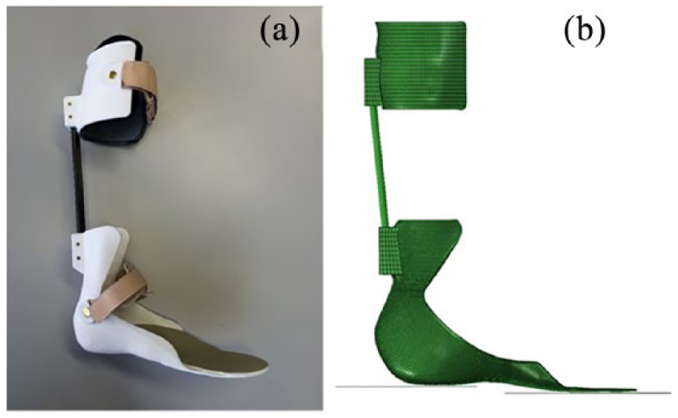
(a) Example of a design of ankle foot orthosis (AFO) and (b) the virtual representation.
Therefore, the aim of this article is to present a complete review including the most representative and recent methods for the quantification of AFO mechanical properties, both from the experimental and computational points of view.
Methods
The literature search was performed using the following tools: PubMed, Scopus, Google Scholar, Cochrane Library, ISI Web of Science, and EMBASE, focusing on articles published in English from 1990 onward. The keywords “ankle foot orthosis,” “apparatus,” “stiffness,” “bench,” “testing,” and “rigidity” were used when searching for articles on experimental evaluation of AFOs. For the search for articles on the computational evaluation, the keywords “numerical,” “computational,” “finite element,” and “ankle foot orthosis” were used.
Results
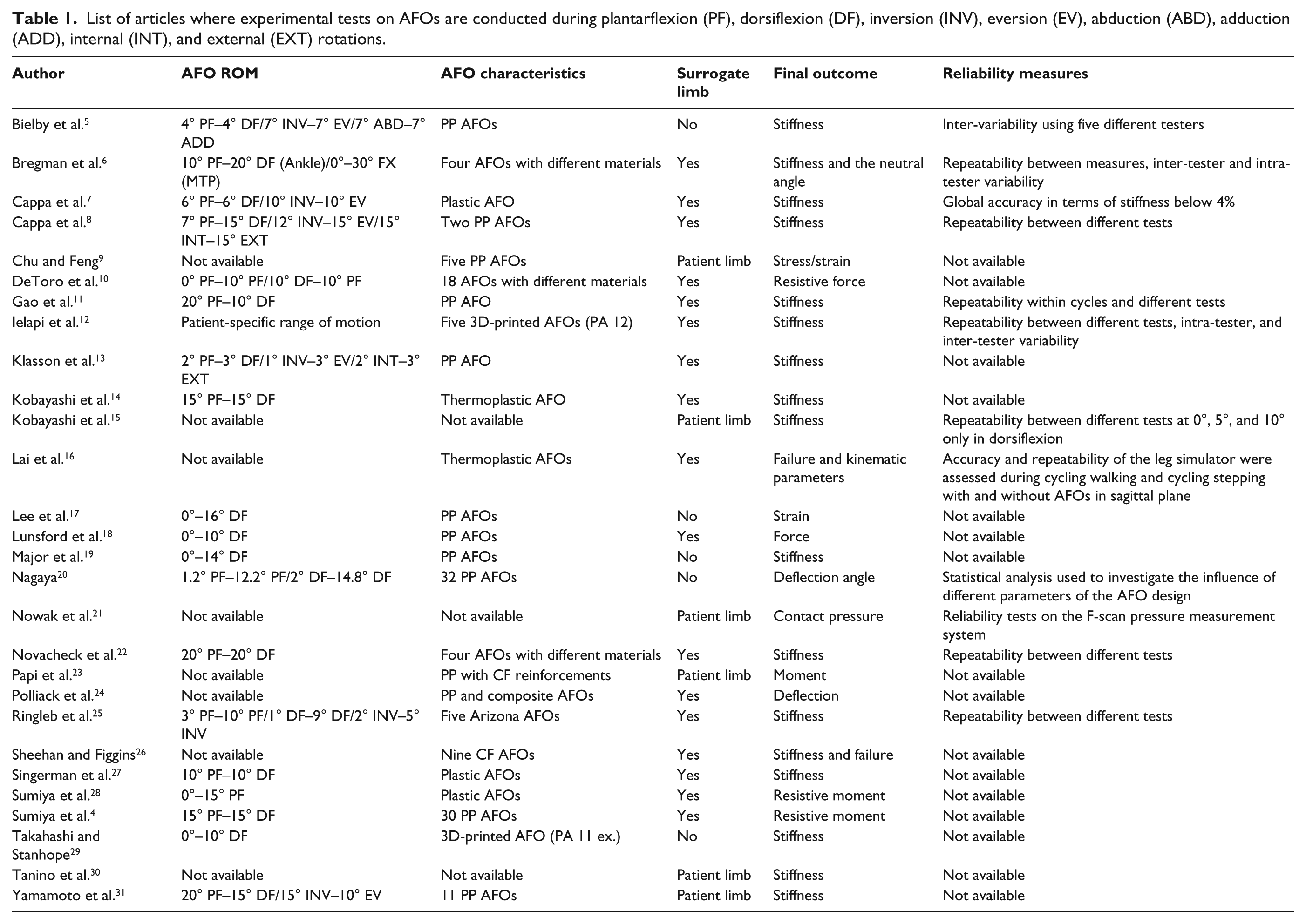
A total of 46 suitable articles were identified and subdivided into three classes; each class was then subdivided into more sections in order to group the articles with common features. In Table 1, the articles that describe the quantification of AFO mechanical properties through experimental methods are listed. In Table 2, the articles that only show a virtual representation of AFO are listed, while in Table 3, the articles that show a combination of experimental and computational results are listed.
List of articles where experimental tests on AFOs are conducted during plantarflexion (PF), dorsiflexion (DF), inversion (INV), eversion (EV), abduction (ABD), adduction (ADD), internal (INT), and external (EXT) rotations.
List of articles where finite element models of AFOs are used.
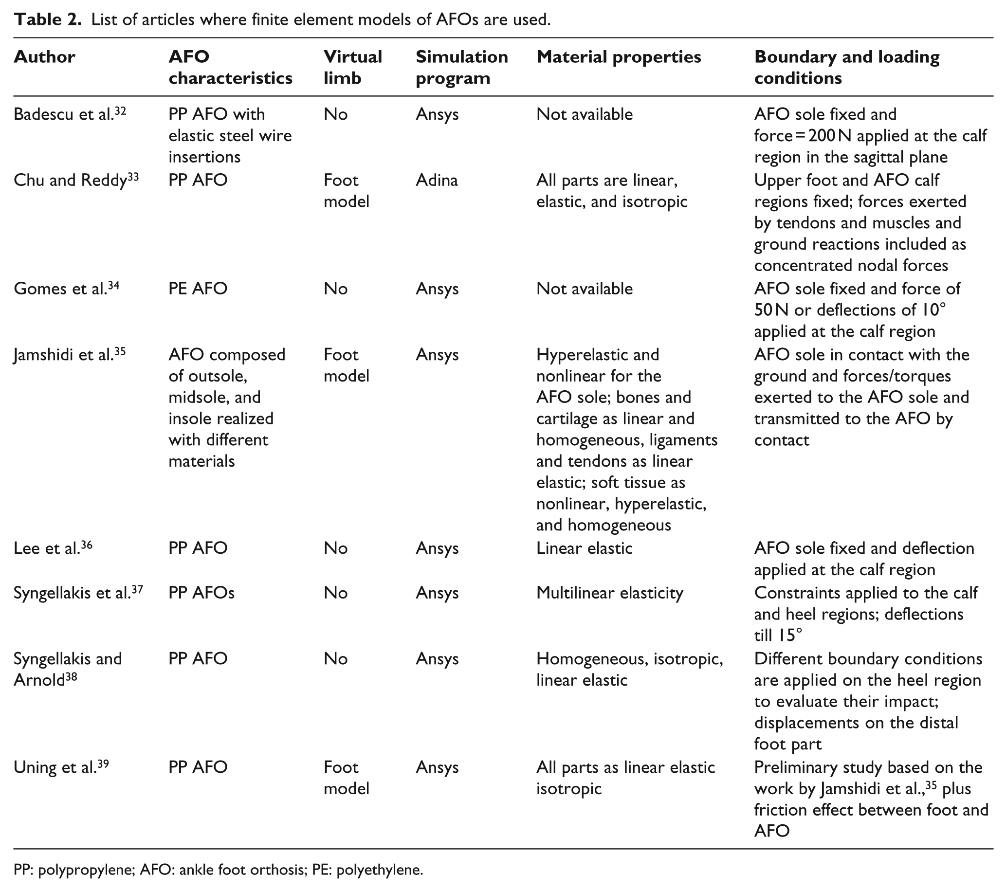
PP: polypropylene; AFO: ankle foot orthosis; PE: polyethylene.
List of articles where experimental tests and finite element models of AFOs are used.
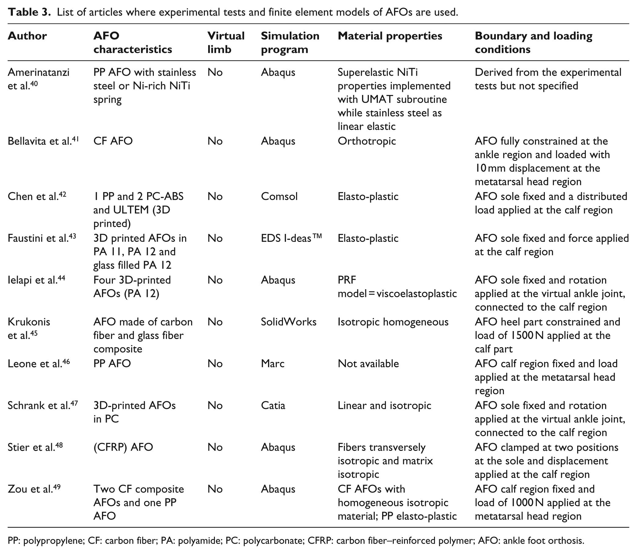
PP: polypropylene; CF: carbon fiber; PA: polyamide; PC: polycarbonate; CFRP: carbon fiber–reinforced polymer; AFO: ankle foot orthosis.
Experimental tests on AFOs
A total of 28 articles describe how the mechanical properties of AFOs are experimentally determined; they can be divided in two categories: studies that involve the use of a test rig, in which the AFOs are inserted, and functional analyses, where the AFOs are measured while the patient is involved in daily activities, such as walking and running. 50
Test rig analyses on AFOs
In the majority of the articles of this category, the main focus is on measuring the stiffness of the AFOs in the sagittal plane through either a manual4,5–7,10,13,15–18,20,22,24,27– 29 or automated test rig.8,11,12,14,19,25,26,31 A definition of the term stiffness was provided by Bregman et al. 6 as the moment around the ankle joint exerted by the AFO per degree of ankle joint rotation (Figure 2) and it is measured in N m/°. While AFO stiffness is the most common focus, some authors refer to other mechanical properties such as strain or resistive force (Table 1). The other features considered in this category are: planes and ranges of motion, AFO alignment, surrogate limb use, speed, and reliability of the stiffness measures.
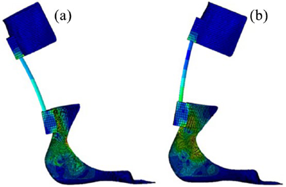
Virtual representation of an AFO, subjected to ankle joint rotation in the sagittal plane during (a) plantarflexion and (b) dorsiflexion.
Planes and ranges of motion
In general, a complete assessment of the AFOs can be obtained if the quantification of the stiffness is realized in all the three planes of motion (sagittal, frontal, and transverse),5,8,13 where plantarflexion (PF)/dorsiflexion (DF), inversion (INV)/eversion (EV) and internal (INT)/external (EXT) rotations are defined. Dorsiflexion is the movement of the calf part toward the foot part and plantarflexion the opposite. Inversion and internal rotation represent an internal motion of the foot, respectively, in the frontal plane and transverse plane, while eversion and external rotation represent the reverse movements. When the terms abduction (ABD)/adduction (ADD) are used, they usually refer to the movements of the forefoot in the transverse plane. Bregman et al. 6 quantified not only the stiffness of the AFO around the ankle joint but also the stiffness around the metatarsal-phalangeal (MTP) joint. In addition, they also determined the AFO neutral angle around the ankle and the MTP joint, which they considered important parameters. Most of the analyses impose a predefined range of motion which reaches 20° of dorsiflexion and plantarflexion, 15° of inversion and eversion, and 15° of abduction and adduction as maximum values.
AFO alignment
Ielapi et al. 12 constructed an automated experimental setup where they use patient-specific ranges of motion previously derived from the gait analysis. In particular, the stiffness is quantified around an axis accurately aligned to the anatomical ankle joint, which is imposed using patient-specific medium-density fiberboard (MDF) blocks that contain the patients’ anatomical points. Imposing the same alignment between the foot and the AFO is important for obtaining reliable measures that can be used for validating eventual finite element (FE) models. The importance of the alignment was also studied by Takahashi and Stanhope, 29 who assess how providing a load with a different orientation could influence the stiffness values, and Gao et al., 11 who evaluate the alignment of an AFO with respect to the motor shaft.
Surrogate limb use
The use of a surrogate limb is usually included when AFOs are tested in experimental bench tests, which serves to fixate the AFO on the ground or for providing the deflection. In fact, experimental tests are normally effected with the AFO blocked on one side (typically the sole), while the other side (calf part) is deflected. Sometimes the fixation includes the use of bolt or screw, which may even be destructive for the AFO.4,10,13,19,22,24,28 In two articles, the limb of the patient was used directly: Kobayashi et al. 15 calculated the stiffness on 10 patients in the sagittal plane, while Yamamoto et al. 31 used a muscle training machine to quantify the stiffness also in the frontal plane.
Impact of other parameters
Other parameters, such as speed, which cannot be accurately controlled when manual setups are used, can affect the behavior of the devices, especially when they are tested cyclically. Despite this, two studies22,31 declare that the speed does not affect the behavior of the AFOs assessed. Another parameter is the reliability. Not all the studies report intra- or inter-tester variability (Table 1).
Functional analyses on AFOs
Functional analyses23,30 usually imply the use of strain gauges, which are easily applicable along the geometry of the AFOs for evaluating their performance while the patient is involved in daily activities like walking and running. Chu and Feng 9 calculated the stress/strain acting on five polypropylene (PP) AFOs by identifying the maximum stresses during the heel strike and toe off. They were located on the AFO ankle region, a condition that might bring failure, consistent with the clinical experience. Nowak et al. 21 evaluated the contact pressure between the AFO and the patient leg. It was acquired real time through an F-scan pressure measurement system (Tekscan, Boston, MA, USA) to detect the areas with less contact pressure, in order to help optimize the design of the devices.
FE models of AFOs
Table 2 lists eight articles which describe a procedure for realizing a virtual representation of AFOs, which were further subdivided whether they used or have not used a virtual representation of the patients’ limb. These models are mainly developed to evaluate the stiffness or the location of stress and strain along the geometry of the devices. The most common procedure is to start from a patient-specific geometric model obtained from laser scans or CAD files. Then, the AFO model is imported in a FE program, where proper material properties, loading, and boundary conditions are applied for achieving the best representation of the AFOs’ behavior.
Inclusion of the virtual representation of the patients’ limb
The inclusion of the virtual patients’ limb requires a significant increase in the modeling difficulty since other parameters, such as the material properties of the foot, leg, and contact properties, need to be considered. Such an approach was used in three studies: Jamshidi et al. 35 proposed a representation of an AFO in combination with a foot model, where bones, cartilage, ligaments, tendons, and soft tissue were included. Bones and cartilage had elastic, linear, and homogeneous material properties and were modeled as three-dimensional (3D) quadratic elements. Ligaments and tendon were linear elastic, in order to bear only tension forces. For the soft tissue, the material was nonlinear, hyperelastic, and homogeneous, while the sole of the AFO was divided into outsole, midsole, and insole with different materials with hyperelastic nonlinear properties chosen for each. The goal was to study and optimize the function of the AFO in the specific case of abnormal gait, by minimizing the stress on the patient’s sole. Therefore, it was possible to define time-dependent forces and torques, exerted to the AFO sole, which were previously acquired experimentally using a force plate, while the foot was in contact with the ground. By imposing the contact between the sole and the foot, the forces were transmitted and even the effect on bones and tendons of the loaded AFO was continuously modeled.
Chu and Reddy 33 instead defined all the involved parts as linear, elastic, and isotropic. The simulation required the fixation of the upper part of the foot and the AFO (calf region) to simulate the AFO strap action on the leg. Forces exerted in the Achilles tendon or in the flexor/extensor muscles tendons during foot motion and ground reactions were included as concentrated nodal forces. Maximum values of peak stresses were found around the AFO ankle and heel region; high stress concentrations around the ankle region are consistent with the common clinical observation that this area is more susceptible to fatigue failure. In this article, no friction was considered between the different components. Therefore, Uning et al., 39 based on this work, 33 illustrated a methodology for simulating the AFO behavior, by including a friction coefficient between the AFO and foot. However, this was a preliminary investigation and no results were reported.
No inclusion of the virtual representation of the patients’ limb
In this section, articles not including a virtual representation of the patients’ limb are inserted: in the most recent study, 34 the impact of using structural reinforcements in different zones of a polyethylene (PE) AFO during the stance phase was investigated. The basic (un-reinforced) AFO model was modified to create seven additional models with reinforcements in different zones. The analysis consisted in applying a force of 50 N or a displacement resulting in 10° of dorsiflexion on the proximal region of the AFO, while the sole remained fixed. Badescu et al. 32 instead simulated the behavior of two PP AFOs, in order to assess how elastic steel wire insertions influence the stress/strain values on the AFOs, since they believed this might be a new approach for their manufacturing process. The analysis required constraining the sole and applying a force of 200 N to the calf region and demonstrated how the ankle area (area with the highest strain) is less subjected to stresses when the steel insertions are included. Lee et al. 36 also evaluated a PP AFO, during dorsiflexion and plantarflexion, respectively, for a range of 20° and 10°, while the sole was constrained. The highest stresses were seen around the trimlines of the ankle part in agreement with other works. This information was used to perform a topology optimization, which showed that a 50% optimization of the volume of the trimlines can be applied.
PP AFOs were also investigated by Syngellakis et al. in two different studies; in the oldest one, 37 they gave more focus on modeling and predicting the nonlinear behavior of the AFO, by including the material nonlinearities and large deformation effects. A geometrical model of the AFO was realized by taking as a starting point a subject leg, which was then cut according to arbitrarily selected geometric parameters of the AFO. The AFO (thickness of 2 mm) was then meshed with eight-node quadratic shell elements (549 in total) and nonlinear properties were provided using eight points extracted from experimental graphs, in order to define a multilinear elasticity. Partial constraints were applied to all the nodes of two areas in the calf region, for simulating the calf strap action and allowing the AFO to move up and down the calf and undergo internal and external rotations. Other constraints were also imposed on the heel region to simulate the shoe and foot. Plantarflexion and dorsiflexion were imposed with 15° of rotation and the results compared to the experimental outcomes reported by Sumiya et al.4,28
In the most recent article, 38 the authors aimed to assess the effect of changing parameters, such as geometry, loading, and boundary conditions. The AFO was divided into several areas and different thickness values were provided for each area for simulating the characteristics of a vacuum-formed AFO. The mesh was realized with triangular and quadratic eight-node shell elements, while the boundary conditions were similar to the previous study. The comparison between an AFO with a uniform and a non-uniform thickness showed a small effect in terms of stiffness and stress. By changing the constraints on the heel region, more differences were obtained, indicating how the magnitude and distribution of the stress and moment are dependent on the distribution of the imposed deformation.
Combination of experimental tests and FE models of AFOs
Table 3 shows a list of the articles in which a comparison between the experimental and computational results on AFOs is provided. The articles of this category are subdivided depending on the imposed loading and boundary conditions. None of these articles included a virtual patient limb.
Fixation of the AFO foot region and load applied at the calf region
In the most recent article, 44 the stiffness of four patient-specific 3D-printed AFOs around the ankle joint, during dorsiflexion/plantarflexion, is virtually quantified and reported with related stress values. The devices were realized in PA12 and the boundary and loading conditions were applied in order to replicate the results coming from a dedicated experimental setup. 12 The validation of the models was facilitated using a parallel rheological model (PRF) which allowed representation of the viscoelastoplastic properties of the material. The material model was obtained from experimental tests on material samples. 51 Faustini et al. 43 tested AFOs realized in PA11, PA12, and glass-filled PA12 through selective laser sintering (SLS). The aim was to validate the stiffness values and evaluate the material dissipation energy and the ability to withstand large deformations (by destructive tests). In terms of dissipated energy, the best performing was the PA11 AFO, although not as good as a carbon fiber (CF) AFO, which is used as comparison. The PA11 AFO was the only one which survived the destructive tests, revealing the flexibility properties of PA11.
Schrank et al. 47 simulated and tested polycarbonate (PC) AFOs in the sagittal plane during dorsiflexion. When using the elastic modulus provided by the manufacturer, the validation of the stiffness results gave an error of 15.3%, which decreased when a new elastic modulus, derived from the experimental tests, was used. The reliability of the experimental measures was also evaluated, showing a maximum test–retest error of 4.7%. Chen et al. 42 tested two 3D-printed (polycarbonate-acrylonitrile butadiene styrene (PC-ABS) and ULTEM materials) and one PP AFOs using strain gauges while a subject was walking. The FE simulations were created to calculate static and dynamic loading conditions during the gait cycle and to predict stress, strain, and bending stiffness of the AFO.
CF AFOs were used by Krukonis et al. 45 for identifying the most loaded parts: static tests were conducted by fixing the heel portion of the AFO and loading the tibia with 1500 N, simulating the weight of a patient of 150 kg. Dynamic experiments were conducted to evaluate the force distribution on the AFO during different daily actions on two subjects (60 and 80 kg). Static and dynamic tests identified the same most loaded part, namely, at the beginning of the spring part, close to the foot region. Stier et al., 48 instead, clamped the sole of a carbon fiber–reinforced polymer (CFRP) AFO and loaded the calf part with displacements at 2 mm/min in dorsiflexion using a punch, which was implemented in the simulation considering a frictionless contact with the calf.
Fixation of the AFO calf region and load applied at the metatarsal head region
Bellavita et al. 41 studied the stresses during the propulsive action of the foot in the gait cycle: while a CF AFO was fully constrained at the ankle level, a rigid rod applied a deflection in the vertical direction at the metatarsal region causing dorsiflexion. In the simulations, the bar was also represented, imposing the hard contact without friction with the AFO. Simulations were then used to predict how geometry variations change AFO stiffness. Zou et al. 49 blocked a CF AFO (and a PP AFO) in proximity of the shank part, where the calf straps are located, while the load (calculated as 1.3 × patient’s weight) was applied on the AFO sole by a cylindrical device with a rate of 8 mm/min. The friction coefficient between cylinder and AFO was equal to 0.1. In the same study, the energy return of the AFOs, as the area contained in the loop, and the fracture analysis were also evaluated. Good results were found for the CF AFO, while they were inaccurate for the PP AFO. Similar boundary and loading conditions were applied on the PP AFO tested by Leone et al.: 46 by increasing the experimental load, they noticed it was possible to reach structural failure through instability; computationally, a refinement in terms of material model and AFO geometry was needed to reach better results.
Not specified boundary and loading conditions
Last model considered 42 took into account an AFO containing a hinge made of Ni-rich NiTi alloy for studying its superelastic behavior; in fact, NiTi alloys can recover large amounts of deformation in comparison with other materials. A motion analysis was performed on a subject during walking using the NiTi spring in comparison with a conventional stainless steel spring. Better results were found for the NiTi spring, but further evaluations were needed.
Conclusion
In this literature review, 46 papers were considered and subdivided into three categories based on whether they presented experimental or computational results or a combination of both; each category was then subdivided into more sections depending on the features contained in each article. Several experimental setups (Table 1) were realized in the past for quantifying the mechanical properties of the AFOs, mainly for assessing the stiffness of the devices during plantarflexion or dorsiflexion in the sagittal plane. The goal of this approach was to represent the behavior of the devices during the ankle rocker of the stance phase when the foot is in complete contact with the ground. However, performing experimental tests is a time-consuming activity and the construction of experimental setups is a complex operation. An important factor, which was not always addressed, was the reliability of the setups, which plays a big role in the final outcome. Other parameters such as the use of a surrogate limb or the alignment of the AFO with the anatomical ankle joint should not be neglected, as it should help to better mimic the real-life conditions (Table 1). Some of the articles presented in Table 1 were included in a previous literature study, 50 which only includes studies until 2010. The current literature review considers 11 more articles, realized before and after 2010, including new test rig applications5,11,12,15–17,26,29 and functional analyses21,23,30 and investigating important parameters which were not covered before, such as the alignment of the AFOs.11,12,29 In particular, a novel study from Ielapi et al. 12 experienced that aligning the AFOs in the setup to their anatomical ankle joint, location of which is derived from the previous gait assessment on the patients, is important for obtaining reliable and repeatable stiffness measures. This could facilitate the validation of the computational models of the patient-specific AFOs, as realized by the same research group. 44
Computational analyses (Table 2) are a faster tool for predicting important parameters of the AFOs: the main difficulty consists in finding the appropriate boundary and loading conditions that reflect real-life situation well enough. In addition, the choice of a suitable material model is critical, since most of the materials used (PA, PP, or CF) exhibit viscoelastic properties, which need to be considered for a full description of the material behavior under cyclic loading. In general, most of the simulations focused on the evaluation of the AFOs in the sagittal plane, usually providing a full constraint of the AFO sole and a load at the calf region or vice versa, a full constraint at the calf region and a load applied at the metatarsal head region. When talking about computational models, a mesh sensitivity analysis should also be included,38,40,44 for assessing that the results are independent of the mesh size and density. Moreover, they need to be validated in order to prove they can address reliable information: this is accomplished by most of the studies listed in Table 3; however, some of them require further refinements/evaluations for providing an optimal validation.40,46 Based on the analyzed studies, the appropriate methodology for the quantification of the AFOs behavior would be to use advanced computational models, constructed with accurate material properties and boundary/loading conditions, which are validated through experimental techniques, in order to mimic the real-life conditions. In fact, we believe that the use of validated FE models represents the best approach for predicting the mechanical properties of the AFOs, which can optimize the manufacturing process of the devices before their realization and help gaining insight in their prescription process.
Footnotes
Author contribution
A.I. realized the literature review and drafted the manuscript. M.F. and M.D.B. provided guidance for the selection of the articles and realization of the manuscript. All authors read and approved the final manuscript.
Declaration of conflicting interests
The author(s) declared no potential conflicts of interest with respect to the research, authorship, and/or publication of this article.
Funding
The author(s) disclosed receipt of the following financial support for the research, authorship, and/or publication of this article: This research was funded by VLAIO (Flanders Innovation & Entrepreneurship) and the A_STREAM_AFO project (Applied Structural Engineering of AM Materials for Ankle Foot Orthosis; project numbers: 140164 and 140165) under the SIM (Strategic Initiative Materials in Flanders) research program STREAM (STRuctural Engineering materials through Additive Manufacturing).