
Abstract
Background:
No studies have determined the optimal location and angular orientation for orthotic dorsal control mechanisms (e.g. dorsal foot strap) for use in lower limb orthoses to resist foot motion for maximum user function and comfort.
Objectives:
To determine the optimal dorsal location and angular orientation of an orthotic control mechanism to resist foot movements associated with heel rise.
Study design:
An in vitro cadaveric study quantified the dorsal force required to resist foot motion.
Methods:
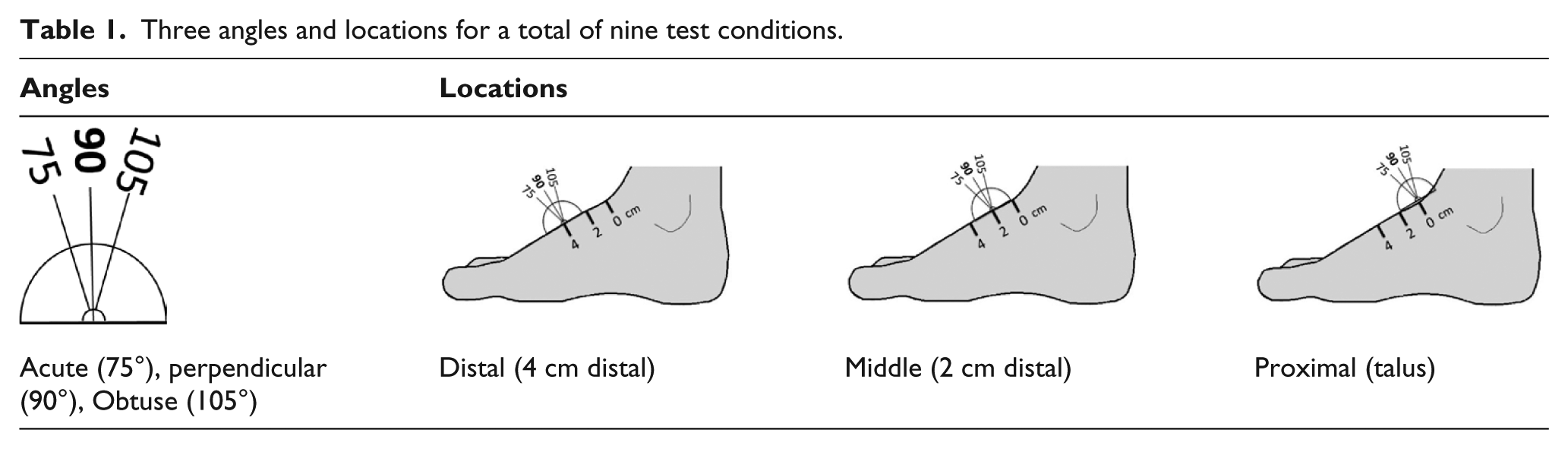
The study simulated heel rise and quantified the force of a dorsal control mechanism in nine test conditions comprising three angles (75°, 90°, and 105°) and three longitudinal axis positions at 2.0 cm increments.
Results:
The test condition representing the longest lever arm (proximal location) applied at an obtuse angle (105°) required the least force (55.6 N) to constrain foot motion, whereas the shortest lever arm (distal location) at the acute angle (75°) required the greatest force (90.4 N) to constrain foot motion.
Conclusion:
To resist foot motion relative to the orthosis, clinicians should aim for the most proximal placement (longest lever arm) at an obtuse angle (105°) with the intention that the resultant controlling force be perpendicular to the bony structure.
Clinical relevance
A dorsal foot control strap applies a critical orthotic corrective force, as part of a force couple to restrict motion of the foot and shank in lower limb orthoses. Foundational orthotic principles that stipulate optimal clinical placement and angular orientation are necessary to ensure maximum function and comfort to users.
Background
A dorsal motion control mechanism, usually a strap, is a common feature on lower limb orthoses (e.g. ankle–foot orthoses (AFOs)). The purpose of a dorsal foot strap is to maintain foot and shank position, but more specifically to limit motion between the foot and the orthosis. Movement of the foot is restricted by means of a force couple, where the dorsal strap serves as the corrective force and opposed by two counter forces, one, respectively, at the posterior proximal region of an AFO’s calf section and the other at the plantar aspect of the metatarsal heads applied by the foot section of the orthosis (Figure 1). The direction forces are applied and the length of the lever arms determines the efficiency and performance of the force couple that the orthosis employs. Theoretically, the ideal performance of an orthosis is one in which there are minimal displacements between the orthosis and the limb since any undesirable movement between the orthosis and the limb represents inefficiencies in the motion control capabilities of the orthosis.
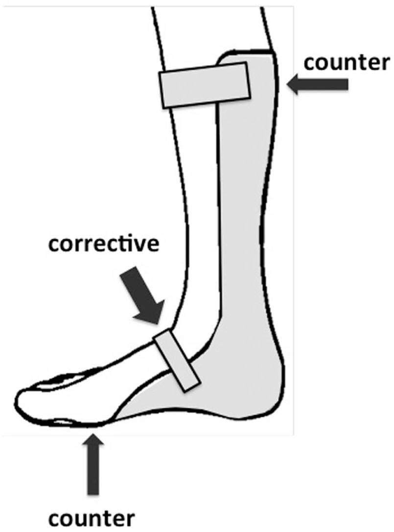
Three-point force couple used to control ankle plantar flexion with an AFO.
To ensure the best possible fit and comfort for the user, the force systems incorporated into orthoses aim to minimize the magnitude of forces applied to the body by maximizing the leverage, the direction of the forces and distributing forces over large areas. Although orthotists have applied these concepts in practice for centuries, no scientific studies have evaluated the specific clinical design features to resist heel rise in an orthosis with a dorsal orthotic constraint mechanism (e.g. strap). One reference in the literature, which represents current clinical practice, suggests the angulation of the orthotic dorsal strap should be directed toward the posterior calcaneus. 1 Orthotists often cite that the dorsal strap should be oriented at a 45° angle to the plantar aspect of an orthoses’ foot piece, although we could not find a reference in the literature with this specification. With no orthotic design principles for a dorsal strap for a scientific study, orthotists are left with experience or evidence-based decisions on how to improve fit, comfort or function, related to orthotic control of heel rise in lower limb orthoses.
The purpose of the study was to determine the optimal longitudinal axis position and the angular orientation of an orthotic dorsal motion control mechanism (e.g. strap), to constrain heel rise within a lower limb orthosis (e.g. AFO). Founded on basic principles of physics, we hypothesized that the optimal angular direction of the force application would be perpendicular to the bony structure of the foot, and for maximum leverage, the force application point would be furthest from the axis of rotation (i.e. most proximal) of the metatarsal phalangeal joints of the foot, which represent its pivot point during heel rise. To test the hypothesis, we measured force with a dorsal orthotic motion control mechanism (i.e. a 1.0-cm round aluminum bar) attached to a load cell, in a cadaveric test setup that simulated heel rise. Nine test conditions were evaluated with combinations of three angles (75°, 90°, and 105°) and three longitudinal axis positions at 2.0 cm increments. Measurements of test conditions that resulted in the least amount of force to constrain foot movements associated with heel rise would be considered the optimum configuration, whereas the measurements resulting in the largest amount of force would be considered the worst configuration (Table 1).
Three angles and locations for a total of nine test conditions.
Methods
An in vitro cadaveric study was designed that simulated heel rise. Five fresh-frozen cadaveric specimens, disarticulated at the knee, were acquired for the study. Inclusion criteria were primarily based on limb side, given that our apparatus was configured for a left limb for angular measures of heel rise. Limb acquisition and selection were not based on gender, size, or age. The limbs were thawed in a cold water bath on the day of testing. Once thawed, a 34-mm-diameter hole was drilled transversely, medial to lateral, through the proximal tibial plateau region of the limb and a 9.0-mm threaded bolt, 15 cm in length, was inserted through the tibia so that the rod protruded both medially and laterally from the skin.
A custom universal test frame specifically designed for cadaveric testing of limbs was used for the experiment and includes a loading platform, two vertical uprights and a horizontal crossbeam. Heel rise was simulated using a pulley system located vertically above the limb with cables connected to the large bolt traversing the proximal tibia in a medial/lateral orientation (Figure 2(a)). Vertical lift of the tibia was achieved with a dead weight of 111.2 N (25 lbs) to simulate the motion of heel rise. The 111.2 N force represents a slight increase over the approximate force needed by the gastroc–soleus complex to achieve heel rise in an average size adult.2–4 The final weight selected for the test protocol was based on pilot tests. To minimize the posterior translation of the foot, an aluminum bar was placed over the dorsum of the hallux and the second toe and screwed to the test platform.
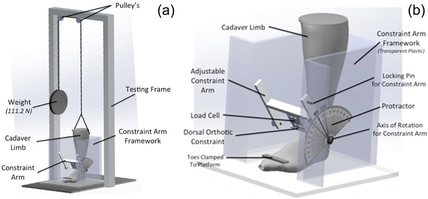
Test Apparatus for Cadaveric Study of Dorsal Constraint Mechanism. (a) Test set-up with testing frame and constraint arm framework. (b) Close-up of constraint arm framework showing cadaver positioned with the orthotic constraint mechanism and load cell.
The test frame was leveled and the angular displacement of the distraction cables was positioned and confirmed to be within the acceptable range of error, less than 5°. The lateral side of the foot and shank was instrumented with a rotational potentiometer, to function as an electro-goniometer, with the mechanical axis of rotation aligned with the anatomical axis of rotation of the metatarsal phalangeal joints. A small aluminum arm extending from the shaft of the potentiometer with a slot at its terminal end was inserted around a cortical bone screw positioned in the apex of the lateral malleoli that allowed unimpeded rotational movement of the potentiometer at the metatarsophalangeal (MTP) joint and smooth un-resisted linear movement over the screw throughout the heel rise motion. Force data were collected with an S-type compression/tension load cell (Chatillon® DSF-R-ND, Largo, FL, USA) that was attached to “H”-shaped aluminum frame, which functioned as the arm of a protractor, to set the desired alignment and angle for the various test conditions (Figure 2(b)). A 1.0 cm diameter and 7.8 cm length, round aluminum bar was secured to the load cell to serve as the orthotic control mechanism that contacted the dorsum of the foot to simulate the constraint force implied by an orthotic strap or shoe enclosure. Force and angle data were recorded with a computer, using a data acquisition program (LabVIEW, National Instruments Corporation, Austin, TX, USA).
Preconditioning of the limb consisted of a 5-min distraction of the limb immediately preceding data collection. The 5-min time frame was determined through pilot study analysis of tissue creep and determination of steady, repeatable distraction force values and angular displacement.
Nine test conditions were studied that comprised an evaluation of three longitudinal axis positions at 2.0 cm increments and three angular orientations in 15° increments, acute (75°), perpendicular (90°), and obtuse (105°) (Figure 3). The proximal location served as the baseline to establish the respective middle and distal longitudinal axis test condition force application points. The talus served as the proximal longitudinal axis position, determined upon clinical palpation. For the angular orientation, the dorsal surface of the foot was used to orient the perpendicular baseline location. An experienced orthotist (certified) determined the location of the talus and the perpendicular orientation to the dorsum of the foot for all the tests. The experimental condition referred to as the middle force location was 2 cm distal to the talus and the distal force location was 4 cm distal to the talus. Obtuse angulation was considered 15° greater than perpendicular with respect to the dorsum of the foot and acute was 15° less than perpendicular with respect to the dorsum of the foot. The order of test conditions was randomized. 5 An additional preconditioning of 5 min was done prior to each test condition. Data were collected for a 6-s period at 300 Hz directly following stabilization. A 10-s distention stabilization period preceded a data collection for each series test runs with each specimen limb. Three trials were conducted for each of the nine test conditions for a total of 27 trials per specimen.
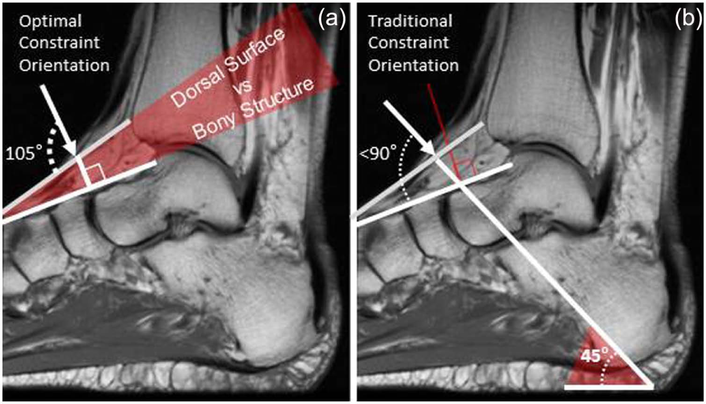
(a) Optimal orthotic dorsal constraint test condition, obtuse (105°), appears to be perpendicular to the bony structure of the foot and (b) orthotists traditionally position the dorsal foot strap at 45° with reference to the plantar aspect of the foot section of the orthosis. The data from this study refute this customary 45° positioning since the resultant angle appears to be acute and less than the theoretical 90° with reference to the dorsal surface and to the bony structure of the foot.
The fourth second of data collection was used to avoid any overlap with initial variance in powering the measurement devices, or premature limb relaxation. Peak force and the force application angle values taken during each trial were used for data analysis. Data were normalized for angular displacement allowing for exact force comparison at the desired angle. Data were not modified to adjust for the angular movement in the pulley system suspending the limb. The angular changes in the direction of pull from the dead weight, which occurred due to vertical displacement of the limb, were calculated and ranged between 0° and 3° of movement.
Results
The proximal obtuse force location and angulation testing condition required the least force to constrain the limb at an average of 55.6 N. The distal acute location and angulation required the most force to constrain the limb at an average of 90.4 N. The force required for constraint increased as the inclination of the force application with respect to the dorsum of the foot decreased and as the force application point moved distally down the foot (Table 2).
Mean peak force (N) for orthotic constraint of heel rise.
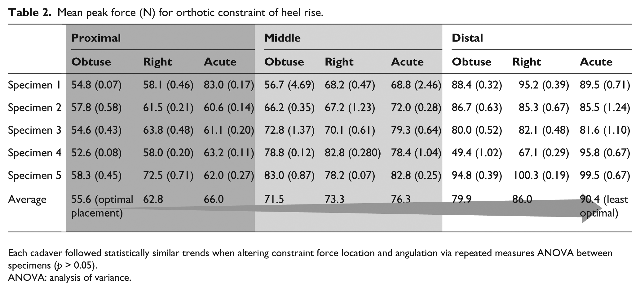
Each cadaver followed statistically similar trends when altering constraint force location and angulation via repeated measures ANOVA between specimens (p > 0.05).
ANOVA: analysis of variance.
With constant angulation, the percent of force needed to constrain the limb increased as location of force moved distally. When the force was applied in the obtuse testing condition, an average of 28.7% more force was needed to constrain the limb with a force application in the middle location (2 cm distal to the talus) than was needed when the force was applied proximally (at the talus) (p < 0.05). The force required to constrain the limb in the distal location (4 cm distal to the talus) was, on average, 44.1% greater than in the proximal condition in the obtuse angulation (p < 0.05). The right and acute angulations followed a similar trend with a distally moving force location, as shown in Table 3.
Percent increase in constraint force compared to optimal placement (proximal obtuse).
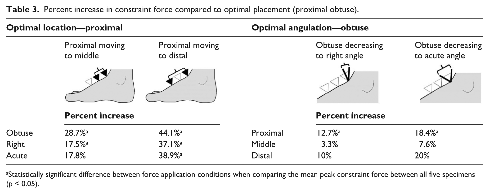
Statistically significant difference between force application conditions when comparing the mean peak constraint force between all five specimens (p < 0.05).
When considering location with a constant force angulation, the force needed for constraint of the limb increased as the inclination decreased with respect to the dorsum of the foot. In the proximal location, when inclination of the constraint force was reduced from obtuse (105° from the dorsum of the foot) to right (perpendicular to the dorsum of the foot), the force required was on average 12.7% greater (p < 0.05). In the same location, if the angulation was again decreased from obtuse to acute (105° from the dorsum of the foot to 75° from the dorsum of the foot), the constraint force required was on average 18.4% greater. Similar trends are seen in the middle and distal locations with decreasing angulation, as shown in Table 3. In all locations, proximal, middle, and distal, the average percentage of force needed to constrain the limb was greater at a right angle than an obtuse angle, and an even larger difference was observed between obtusely and acutely angled force applications.
Statistical analysis was conducted through IBM SPSS Statistics 21 software. The statistical analysis confirms that there was no significant difference between the five specimens, based on a repeated measure analysis of variance (ANOVA) (Greenhouse–Geisser p > 0.05). A statistically significant difference occurs when moving the force application location distally down the foot when angulation is held constant (p < 0.05, paired T-test). A statistically significant difference is also found when decreasing inclination (105° to 90° to 75° with respect to the soft tissue of the foot) when the location optimized at the proximal-most point (p < 0.05).
Discussion
The results from this study supported the maximum leverage aspect of our hypothesis, with the test conditions situated most proximal resulting in the least force output to control heel rise compared to force application points 2.0 and 4.0 cm more distal. In the foot, the axis of rotation during heel rise is the metatarsal phalangeal joints with the metatarsals, tarsi, and calcaneus bones collectively serving as the lever arm, especially as the foot everts to form a solid lever for heel rise and toe off. 6 With regard to the optimal force angulation aspect of our hypothesis, stated as being perpendicular to the bony structure, the data showed the obtuse angle test condition to have the least force (most efficient) and optimal leverage to resist heel rise. However, the angular orientation of the test condition was based on the dorsal surface of the foot and not the underlying skeletal structure; hence, we cannot rule out that the hypothesis was not supported by the results.
We did not have medical imaging to confirm the relationship of the simulated dorsal orthotic foot control test angles (i.e. 75°, 90°, and 105°) to compare their true relationship to the skeletal bony structures. For this study, we adopted a test protocol that emulates what clinicians may typically reference to determine the angular orientation of the dorsal control strap, the foot’s dorsal surface. In a follow-up magnetic resonance imaging (MRI) evaluation, we deduced that the use of the dorsal surface of the foot to clinically determine the proper orientation of a foot control strap may not be a good clinical reference because the tendon and fascia structures dorsal to the skeletal structure do not necessarily represent the anatomical position of the bones, particularly more proximal to the ankle (Figure 3). The results of the study showed that the obtuse angle (105°) was optimal, having the least force (most efficient) required to resist foot motion associated with heel rise (Table 3). We hypothesized that the optimal and most efficient orthotic control force would be perpendicular to the bone structure. Since the data could not fully validate the hypothesis as expected, we sought further explanation to better interpret the results. Close examination of a sagittal MRI of the foot ankle complex provided insight as to why the orthotic force orientation at an obtuse angle (105°) yielded the least force (most efficient) compared to the perpendicular (90°) and acute (75°) angular tests. The obtuse angle (105°) orthotic force orientation was actually aligned perpendicular to the bony structure in the MRI we studied when we assessed the relationship of the dorsal surface of the foot compared to the skeletal bony structure (Figure 3(a)). From the one MRI we evaluated, the foot’s exterior dorsal surface did not reflect the orientation of the underlying skeletal structure, which had a 15° differential compared to the bony structure suggesting that clinicians should seek other ways to determine the optimal, perpendicular orientation to the skeletal bones to resist the motion associated with heel rise within an orthosis. Further research is needed to quantify the relationship of bone structure versus the angulation of the dorsal surface of the foot to establish reliable clinical guidelines for the orientation and placement of orthotic constraints for heel rise.
The findings from this study reveal that the traditional orthotic approaches to the application of a controlling force to resist heel rise may not have the optimal clinical effect as previously assumed actually be acute with regard to the bony structure (Figure 3(b)). Three major tendons are situated anterior to the ankle, tibialis anterior, extensor hallucis longus, and extensor digitorum longus. When these tendons are in tension, the superior and inferior extensor retinacula restrict the tendons from “bowstringing,” although there is still some residual dorsal and anterior migration of tensed tendons with respect to the underlying bony structure. 7 The small amount of residual bowstringing that occurs when the anterior dorsiflexor tendons are in tension can alter the magnitude and direction, a dorsal orthotic constraining force may apply. Therefore, clinicians need to determine whether an orthotic dorsal constraint force will be applied to a tensed tendon, if normal muscle function is present, or more directly to the bony structure if the user presents with paresis of the dorsiflexors, which would have minimal tension. Careful assessment of the proximal dorsal foot anatomy should be considered when constraint of heel rise, with respect to the orthosis, is to be effective and efficient.
Several limitations of the study should be considered when interpreting the results. Since the study used cadaveric limbs, the influence of muscle activity and the function of the dorsal tendon and fascia structures on orthotic constraint of heel rise could not be assessed. The test protocol simulated heel rise in standing and did not represent the movements associated with propulsion during late stance push-off. Repetitive movements associated with the dynamics of walking are very different from the static nature of the test protocol we used and therefore may yield different results. The specimens procured for this study were used in a previous research study and a surgical plantar fasciotomy was performed on all specimens, although this was considered to have minimal clinical implications for studying dorsal orthotic motion constraint.
Conclusion
For optimal constraint of heel rise in an orthosis (e.g. AFO) with a dorsal foot strap that applies the least amount of force to resist motion, clinicians should aim for the most proximal placement (longest lever arm) at an obtuse angle (105°), with the intention that the resultant force application is positioned perpendicular to the bony structure. Clinicians should be cognizant that the foot’s dorsal surface does not necessarily represent the orientation of the underlying bony structure, and that the soft tissue structures traversing the foot may impede optimal control of heel rise within an orthosis, and therefore, a clinical assessment of the anatomy at the location the orthotic constraining force (i.e. dorsal foot strap) should be considered.
Footnotes
Acknowledgements
The authors would like to thank Guay-Haur Shue, PhD, for setting up the electronics and developing the software and Allison Stowers, BS, for her assistance in the data collection during tests.
Author contribution
All authors contributed equally in the preparation of this manuscript.
Declaration of conflicting interests
The authors declare there are no conflicts of interest.
Funding
This work was supported by the Pedorthic Foundation.