
Abstract
Background and Aim:
It has been reported that cycling-specific research relating to participants with an amputation is extremely limited in both volume and frequency. However, practitioners might participate in the development of cycling-specific prosthetic limbs. This technical note presents the development of a successful design of a prosthetic limb developed specifically for competitive cycling.
Technique:
This project resulted in a hollow composite construction which was low in weight and shaped to reduce a rider’s aerodynamic drag.
Discussion:
The new prosthesis reduces the overall mass of more traditional designs by a significant amount yet provides a more aerodynamic shape over traditional approaches. These decisions have yielded a measurable increase in cycling performance. While further refinement is needed to reduce the aerodynamic drag as much as possible, this project highlights the benefits that can exist by optimising the design of sports-specific prosthetic limbs.
Clinical relevance
This project resulted in the creation of a cycling-specific prosthesis which was tailored to the needs of a high-performance environment. Whilst further optimisation is possible, this project provides insight into the development of sports-specific prostheses.
Background and aim
A recent review of the literature has revealed that both research and clinical experience are extremely limited 1 to help guide prosthetists with the creation of cycling-specific prostheses. A traditional prosthesis used for walking can be used for cycling but falls short of two key performance indicators crucial to competitive cycling.
The first is to realise the importance of aerodynamics when cycling competitively by lowering the aerodynamic drag. 2 This even applies to components as proportionally small as a prosthetic limb. 3 Kyle and Burke 4 recommended a hierarchy for addressing the reduction of aerodynamic drag as
Reducing the frontal area;
Streamlining the geometry;
Lowering the surface roughness.
The second goal is to reduce the prosthetic mass as this will reduce the energy the rider will have to expend when accelerating or climbing.
The aim of this technical note is to present and discuss a case study of a high-performance cycling prosthetic limb design undertaken for the London 2012 Paralympic Games. Both participant consent and institutional ethics were obtained prior to this project.
Technique
Participant
A male, international-level cyclist (age = 34, height = 1.72 m and weight = 73 kg) acted as the participant for this case study. The participant had been using a walking prosthesis to cycle prior to this project. Due to a neurologically related disability, the athlete lacked full ankle control of their sound limb.
Design specification
The athlete wished to use the limb to compete across a diverse range of cycling events including the track-based 1 km time trial and 4 km individual pursuit events plus the 20 km outdoor ‘individual time trial’. However, the nature of these events is very different. The track time trial requires maximum effort from a stationary standing-start position to complete the event. Conversely, both the individual pursuit and the individual time trial require a more evenly distributed steady-state power output. As a result, the prosthetic solution needed to accommodate this diverse range of needs.
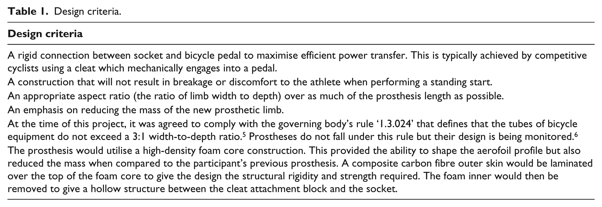
Prior to the design process, the key constraints of the prosthesis design were sourced from peer-reviewed literature and prostheses manufacturers. A summary of these criteria is in Table 1.
Design criteria.
Prosthesis fit
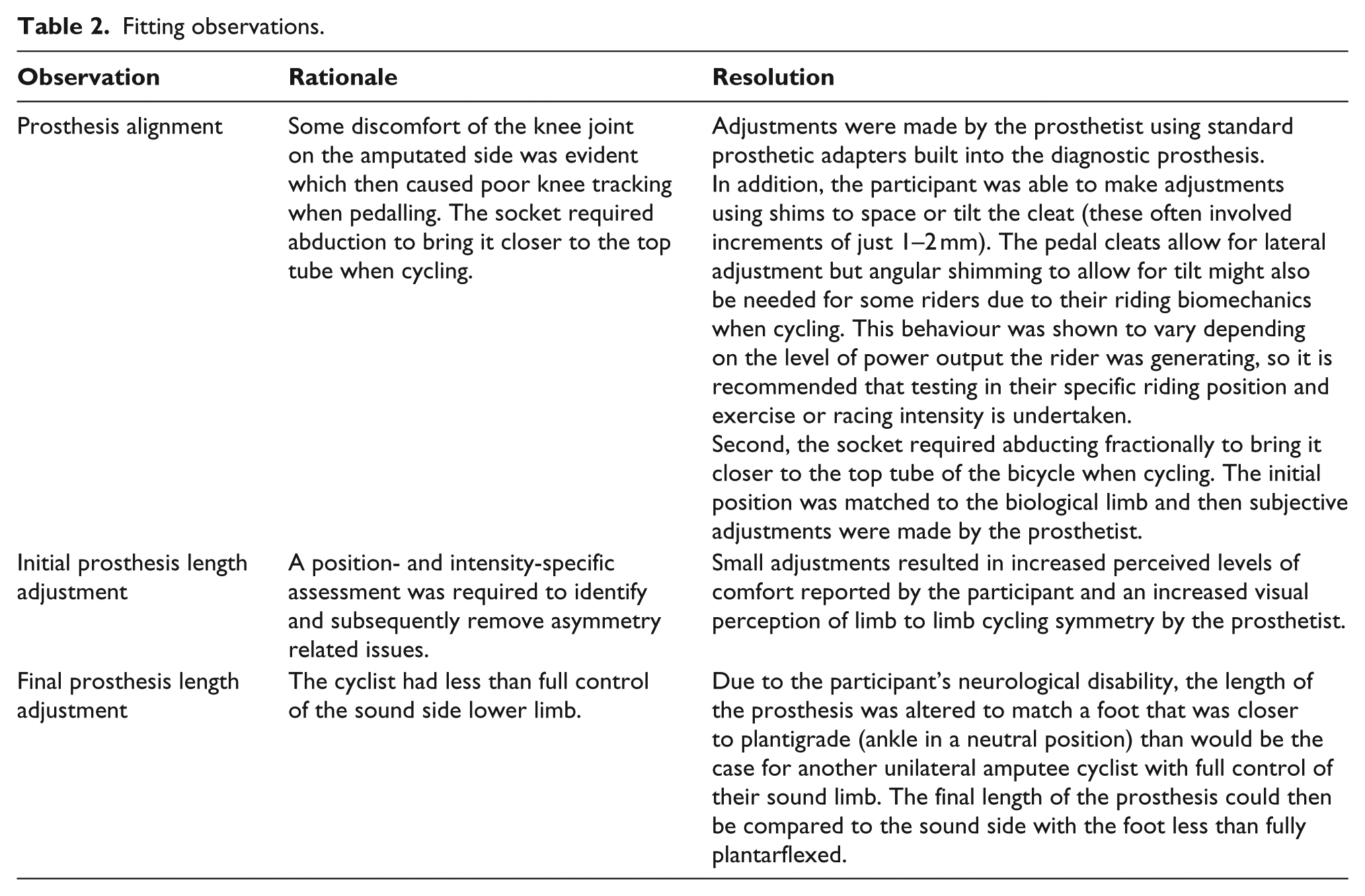
The way the prosthesis is attached to the cyclist is a critical factor in achieving an efficient power transfer. This connection must be as rigid as possible while at the same time being comfortable for the duration of the competitive event. A Seal In X5 liner (Ossur) with valve (Ossur A-551002) was selected as the suspension system. The starting point for the length and alignment of the diagnostic prosthesis was produced by taking a profile of the cyclist’s sound side in the sagittal plane with the foot in a plantarflexed (toe down) position. A measurement was taken from the patellar tendon to the centre of the cycling cleat. This established the initial socket to cleat position. To help with this process in the clinic, the participant used a stationary trainer (a product which attaches a bicycle in a stationary position and allows it to be ridden). Minor adjustments were then made to the length and alignment using a diagnostic prosthesis which was adjustable in six different degrees of freedom and whose measurements would then be transferred to a jig. This jig would place a mandrel inside the proposed socket and lock it in position between both this and the pedal cleat. This would serve as the guide for the final prosthesis. The cyclist subsequently undertook field trials by riding their bicycle in a velodrome at exercise intensities consummate with the power output experienced in their racing. Qualitative feedback and expert observation contributed to the designs refinement. Key observations during these trials are shown in Table 2.
Fitting observations.
Prosthesis form design
An aerofoil form was selected for the pylon region. It has been shown that aerofoil-based bicycle frames offer considerably less drag than a round tube traditional design. 2 To determine which aerofoil profile was most suitable for this application, an accurate measurement of the near vertically angled seat tubes from contemporary wind tunnel validated bicycle frames was undertaken. However, it is conceded that there is some angular variation of the lower leg when cycling.
The aerofoil design was modified further through addition of a Kamm profile. The Kamm concept has been used extensively in both the automotive and aeronautical industries and its definition is that of an aerofoil that is cut when the rear taper reaches 50% of the aerofoils maximum width. This concept has recently been applied to bicycle frame member design. 7 The Kammback principle allows a cut aerofoil to obtain nearly the same aerodynamic performance as an uncut aerofoil. While the optimisation of this profile would require more than a casual application of aerodynamics, it was felt that the design would also provide beneficial levels of lateral and torsional stiffness over that of a traditional aerofoil. 7 This would be of extra benefit to the higher forces of the athlete’s track time trial event. The Kamm width at its narrowest point was defined as the thinnest that the fabrication process was deemed to feasibly achieve and was 36 mm in thickness with a 108 mm aerofoil depth. The aerofoil was tapered further down the pylon area to meet the smaller shape and size of the cleat/foot area.
It is likely that an optimal aerofoil design would be different between indoor and outdoor use but the Kamm design was not specified for a specific wind yaw. Yaw is the net angle of the net airflow that strikes the cyclist and is dictated by riding speed and any external wind speed. In the case of this project, the athlete would only have one prosthesis, so a conservative approach to the aerofoil design was taken. Either way, the Kamm design has been shown to be beneficial in wider ranges of wind yaw. 7
Limb construction
The prosthesis shank and foot region were shaped and manufactured by hand from high-density foam. Templates were used to provide cross-sectional dimensional consistency of the shank and a mid-construction example of the composite being applied over the shaped foam core is shown in Figure 1.
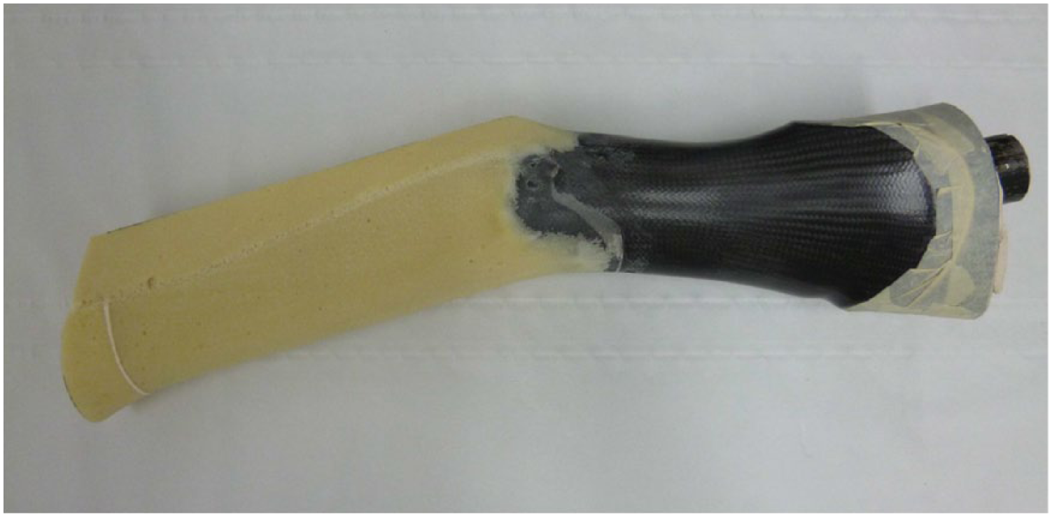
Mid-construction of prosthesis.
A composite construction was then created using three layers of multi-directionally applied 6K carbon fibre with orthocryl laminating resin. Once this was complete, the foam core was removed by boring the foam out using a tool inserted where the cleat would be mounted and by cutting down the centre of the Kamm rear face to remove the foam higher up. This cut would then be re-joined by re-laminating it afterwards. The rotational alignment of the aerofoil was achieved through use of a jig that aligned it exactly perpendicular to the cycling pedal cleat. This stresses the importance of establishing the optimal position of the pedal cleat, prior to final prosthesis construction. The cleat threaded inserts were bonded through the laminated face of the underside of the foot and reinforced using an aluminium metal plate that was imbedded between the three layers of carbon fibre. Some natural reinforcement was created when the cloth was neatly folded around key areas.
Results
The participant’s first-generation limb had a mass of 1.86 kg. The mass of the new prosthetic leg was 0.72 kg, resulting in a reduction in mass of around 1 kg. An image of the completed limb is shown in Figure 2(a) to (c).
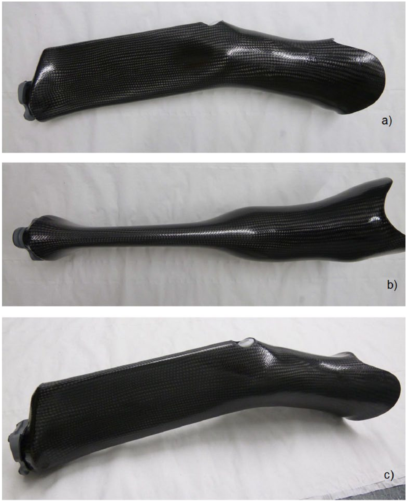
Completed prosthesis in (a) side profile, (b) front profile and (c) 3/4 view.
Discussion
Since this project’s completion, aerodynamic drag measurement has now been applied to a similar design to this limb for the 2016 Paralympic Games and has yielded a potential 23 s time saving over a conventional round shank design when performing a 16.1 km time trial. Within 2 months of this project’s completion, the cyclist won the 2012 World Cycling Time Trial Championships in their disability category.
A 1 kg reduction in mass was a significant saving over the user’s previous prosthesis and reduced the total mass needed to be accelerated from rest in a standing start by approximately 1.1%. For future designs, further improvements in prosthesis mass and aerodynamic drag could be made through the use of pre-preg carbon fibre. This would potentially reduce the profile of the blade area and reduce the mass while maintaining the required strength and rigidity.
It could be suggested that an optimised design could have been generated using computational fluid dynamics (CFD). However, it is not known what impact any airflow interaction and interference of the leg and bicycle would have on each other, and CFD would have to model an exact reproduction of the specific rider and their equipment. This might prove to be an innovative approach in the future but may be cost-prohibitive compared to field testing. Field testing proved essential as the cleat and socket alignment required adjustment that was only apparent when the participant performed trials on their own bicycle at power outputs typical of their specific events. With this in mind, cost-effective field testing methods for this purpose have been formally validated. 3
Key points
An aerofoil is aerodynamically superior to a round-tubed section.
Reduction of the excess mass of a prosthesis is essential for cyclists to reduce their energy expenditure.
Any prosthetic fit or evaluation should be conducted using exercise intensities consummate of the athlete’s chosen events.
Footnotes
Author contribution
All authors contributed equally in the preparation of this manuscript.
Declaration of conflicting interests
The author(s) declared no potential conflicts of interest with respect to the research, authorship and/or publication of this article.
Ethical approval
Institutional ethical approval was obtained for this project.
Funding
The author(s) disclosed receipt of the following financial support for the research, authorship and/or publication of this article: Any associated costs for this project formed part of pro bono assistance given to the participant and were fully underwritten by the author’s employers.