
Abstract
Snowboarding with a below-knee prosthesis is compromised by the limited rotation capabilities of the existing below-knee prostheses, which are designed for use in normal walking. Based on snowboarding range of motion analyses, a novel below-knee prosthesis was designed with the aim to achieve similar range of motions like able-bodied snowboarders. The new prosthesis allows for passive inversion/eversion, passive plantarflexion/dorsiflexion and additional ‘voluntary’ plantarflexion/dorsiflexion initiated by lateral or medial rotation of the upper leg and knee. A prototype was built and was subsequently tested on a single subject, a highly professional snowboarder and candidate for the Olympic Winter Games. The movements of the subject were recorded on video, analyzed and compared to the recorded movements of an able-bodied snowboarder, and a snowboarder with a traditional below-knee prosthesis. The results indicated an increased similarity of inversion/eversion and plantarflexion/dorsiflexion between the snowboarder with the new below-knee prosthesis and the able-bodied snowboarder, whereas the snowboarder with the traditional below-knee prosthesis and the able-bodied snowboarder differed considerably. These results indicate that snowboarding with the new prosthesis is more comparable to able-bodied snowboarding. On a subjective basis this is confirmed by the test subject who stated that: “snowboarding with the new prosthesis is like it was before the amputation!”.
Keywords
Introduction
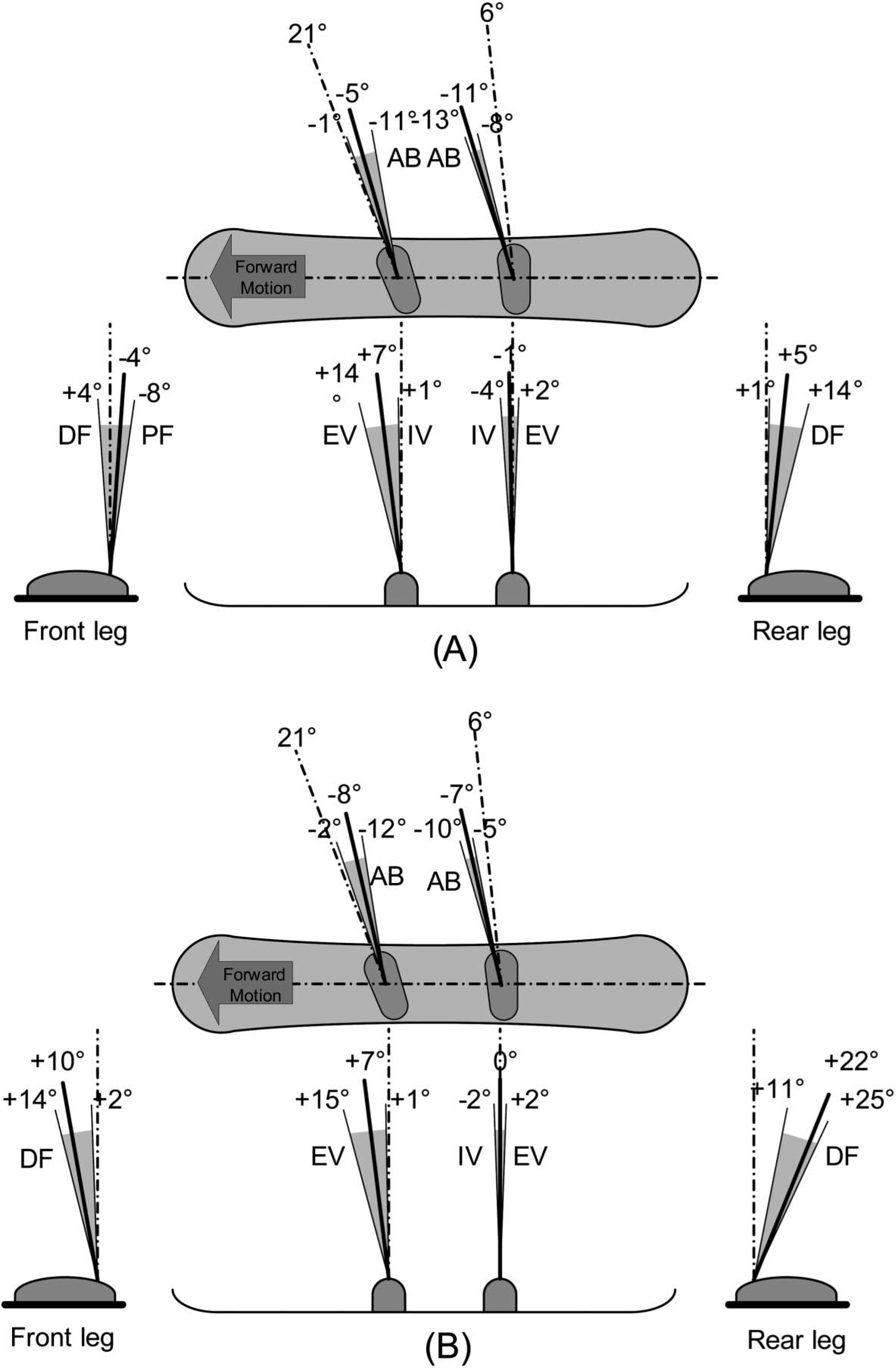
During snowboarding the head, arms and upper body are mainly used to initiate and end a turn whereas the lower body is active during the entire turn, requiring rotations of the foot-, ankle-, knee-, and hip-joints. Because of the absence of a foot and an ankle, someone with a below-knee amputation is limited in performing these motions making snowboarding more difficult. Unfortunately, existing prosthetic components do not provide the necessary passive and/or active rotation possibilities, as most of the prosthesis are set with a fixed alignment. As a result, three major sub-problems can be identified: Due to the fixed alignment of a traditional below-knee prosthesis, the up-right posture of a person with a transtibial amputation on a snowboard differs considerably from a person without an amputation,[1] making snowboarding more challenging. Furthermore, a certain amount of passive rotation ability within the ankle joint is important. Such a rotation is normally used in snowboarding to adapt to the different types of terrain, landing jumps and leaning into turns. The rotations at the ankle used in snowboarding are plantarflexion/dorsiflexion, inversion/eversion, and abduction/adduction[1],[2] (see Figure 1). Traditional below-knee prostheses provide no, or only to a limited amount of such rotations. The majority of below knee prostheses are passive, meaning that the amputee is not able to exert control over the ankle joint. However, ‘voluntary control’ of the plantarflexion/dorsiflexion in a small range of motion would enable the snowboarder to correct the angle of the snowboard with respect to the slope, thus modulating its grip when turning. Degrees of freedom in the ankle joint while snow-boarding. Abduction(AB)/adduction is shown in the top view of the snowboard, dorsiflexion(DF)/plantarflexion(PF) is shown in the front and rear view of the snowboard, with respectively the front and the rear leg shown. Inversion(IV)/eversion(EV) is shown in the side view of the snowboard. The bindings are set at +21° for the front binding and +6° for the rear binding. The solid black line is the rest position and the gray hatched area is the range of motion. (A) Backside turn, (B) Frontside turn. Adapted from[1].
Based on the limitations mentioned above, it was decided to design and construct a new below-knee prosthesis for snowboarding that would allow interaction between the snow-boarding person and the board similar to a person with no amputation.
Methods
Three phases were identified in order to develop the new below-knee prosthesis for snowboarding:
First phase – design criteria
The new design was intended to approximate able-bodied ankle movement during snowboarding. Motion and force analyses of snowboarding were performed to understand snowboarding biomechanics and kinetics required for the design. The following were considered important design criteria: (a) foot angles, (b) passive degrees of freedom, (c) possibility to ‘voluntary’ control the ankle in order to adapt to different slope angles during turning.
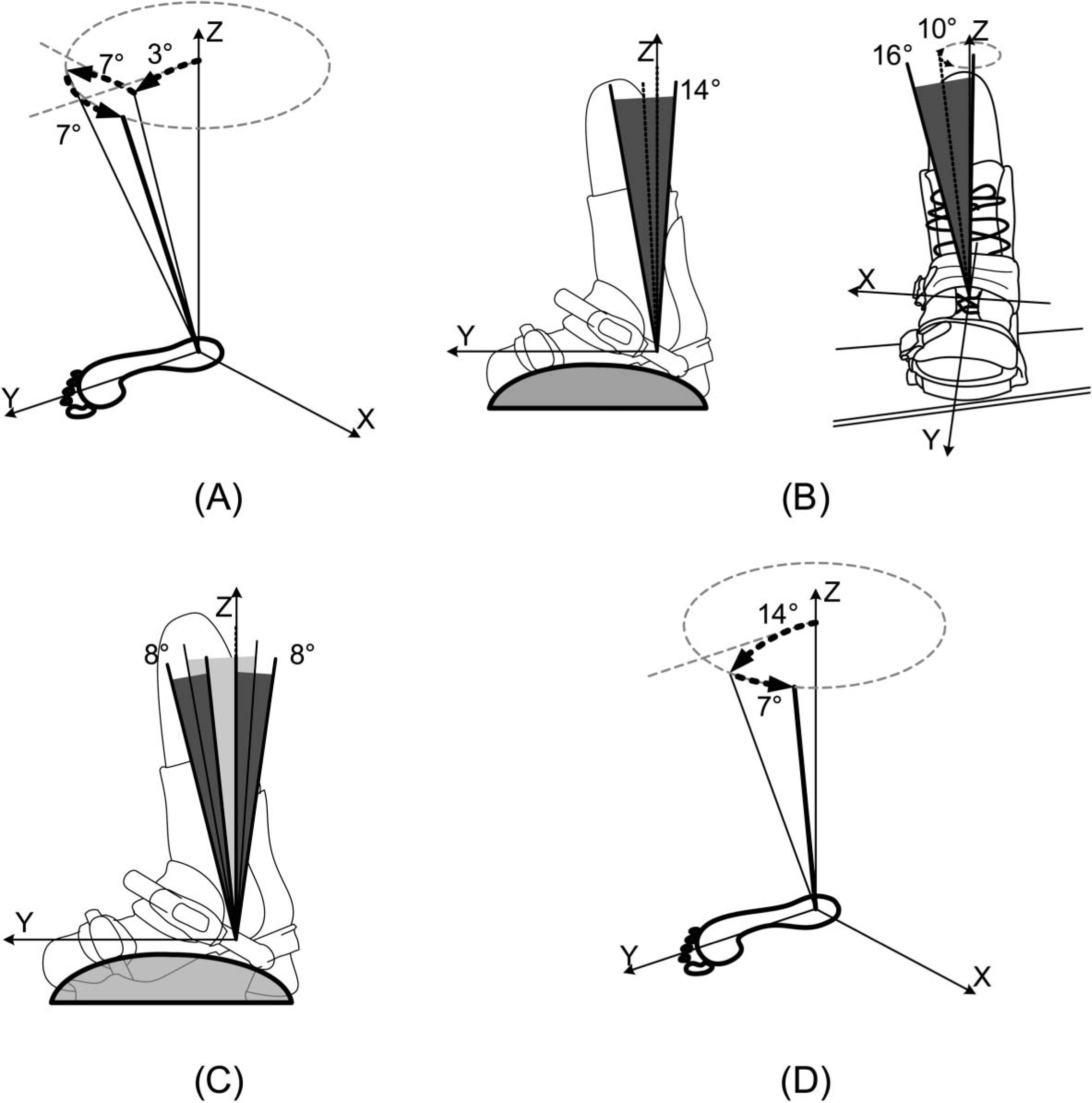
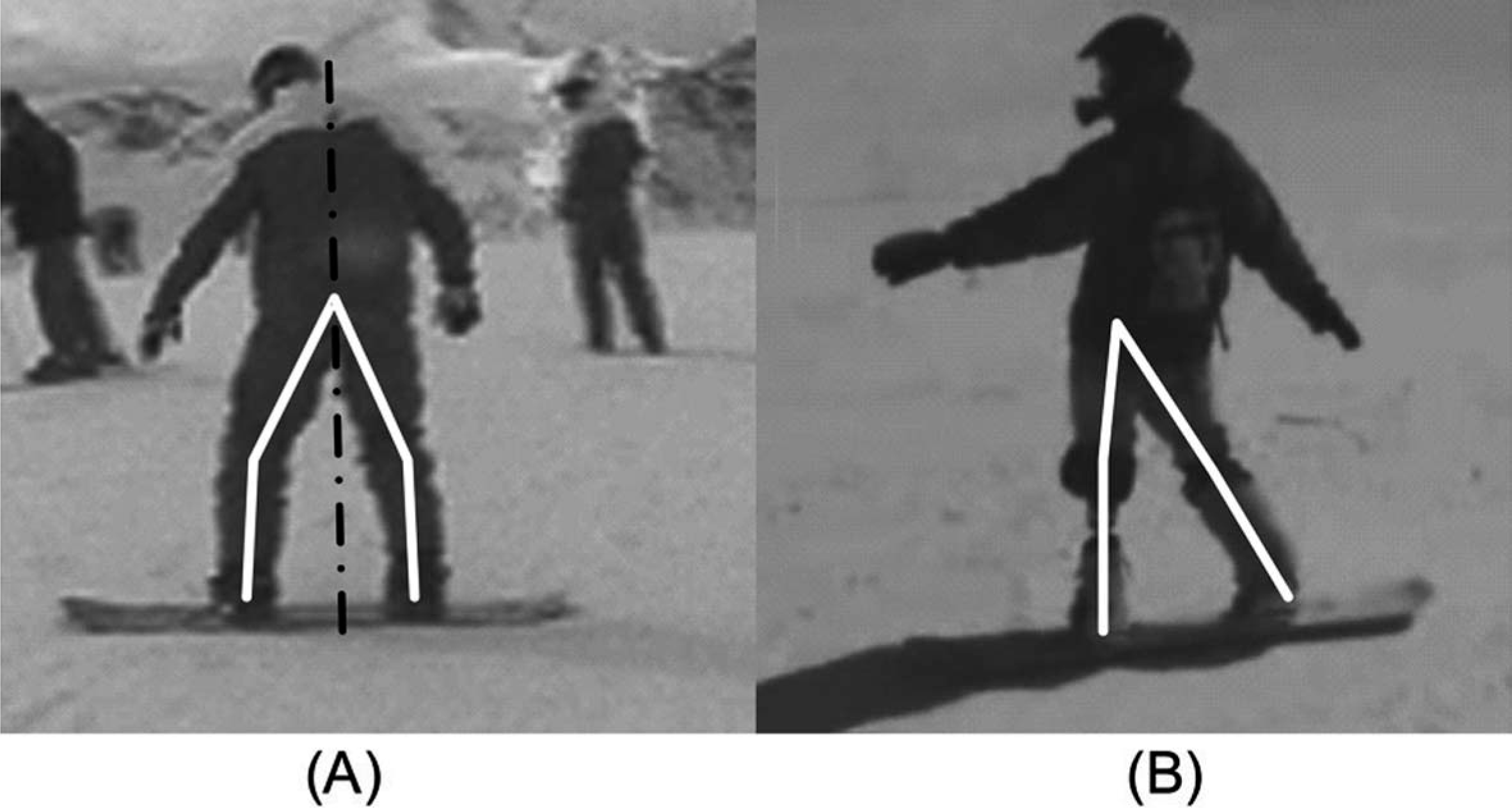
Foot angles: Delorme et al.[1] have determined the range of angles of the ankle for both frontside and the backside turns, Figure 1. The foot of an able-bodied snowboarder is dorsiflexed, everted and adducted with respect to the lower leg while standing on a snowboard. These angles change in backside and front side turning (see Figure 1). The initial stance of an amputee snowboarder differs from an able-bodied snowboarder as seen in Figure 3. Hence, for the new device the mid-range angles of an able-bodied snowboarder were used as initial orientation of the lower leg with respect to the foot: +3° dorsiflexion, +7° eversion, and +7° adduction (see Figure 2A).
(A) Initial setup of the ankle joint for snowboarding of the front leg. The Z-axis represents the lower leg for normal prostheses. The rotations are shown to reach the setup used for the prosthesis for snowboarding, +3° Dorsiflexion, +7° Eversion and +7° Adduction. (B) Passive rotational freedom within the ankle joint for snowboarding. (Left) The passive rotation around the ankle joint, leading to plantarflexion/dorsiflexion. A 14° range of motion is required, which is evenly divided around the initial setup of the ankle indicated by the dotted line. (Right) The passive rotation around the subtalar joint, leading to adduction/abduction and inversion/ eversion. A 16° range of motion is required for the inversion/eversion, which is evenly divided around the initial setup of the ankle indicated by the dotted line. A 10° range of motion is required for the abduction/adduction, which is evenly divided around the initial setup of the ankle indicated by the dotted line. (C) Active control of the plantarflexion and dorsiflexion in the ankle joint. An 8° range of motion is required, which is evenly divided around the end of the passive range of motion discussed in the previous part. This active range of motion is used both at the end of the passive range of motion in the frontside and backside turn. (D) Initial setup of the ankle joint for snowboarding of the rear leg. The Z-axis represents the lower leg for normal prostheses. The rotations are shown to reach the setup used for the prosthesis for snowboarding, +14° Dorsiflexion and +7° Adduction.
Passive degrees of freedom: For the design, ‘passive rotation’ was defined as the rotation from the initial orientation of the lower leg with respect to the foot toward the average angle of the ankle for a frontside or backside turn.[1] The most important rotation is the plantarflexion/dorsiflexion of the ankle. However, inversion/eversion and abduction/adduction have to be possible too (see Figure 1). Taking the initial set-up as a reference, the ranges of motion needed were: +7° plantarflexion and +7° dorsiflexion, +8° inversion and +8° eversion, and +5° abduction and +5° adduction (see Figure 2B).
‘Voluntary control’: The last sub-problem within the below-knee prosthesis is the ‘voluntary control’ of the plantarflexion/dorsiflexion angle, which will result in more overall control in turns. ‘Voluntary control’ means that the snowboarder has the ability to change the supination/pronation rotation within the ankle of the prosthesis in addition and independently of the passive degrees of freedom. The range of motion needed is the amount of rotation between the mid-range angle of the ankle for the frontside and backside turn and the maximum rotation (see
Figure 1). The range of motion necessary for the voluntary control was: +4° dorsiflexion and +4° plantarflexion at the end of the passive range of motion in a frontside turn or in a backside turn, in both cases leading to a total of 8° range of motion (see Figure 2C). With the design criteria found, a new design was conceived, inspired by the anatomy and functionality of the normal human ankle.
Manufacturing of prototype
The newly designed prosthesis was manufactured and subsequently
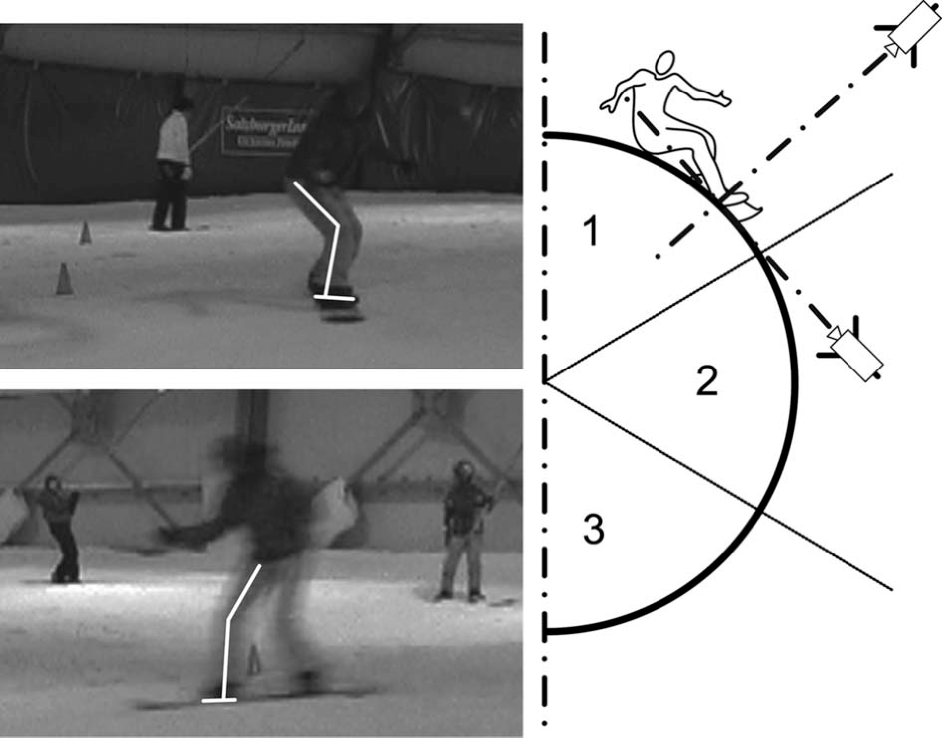
Tested in the laboratory and in the field on a single highly professional subject. In the laboratory the actual passive and active rotation angles achievable were measured and compared to the design criteria. For the field test, usual 3D-motion analysis systems cannot be used because snow reflects infrared light. Instead, two normal HD video cameras were used. Marker strips placed on the leg provided clear indications of the legs' rotation. One camera was placed in line with the subject and the other perpendicular to the subject (see Figure 4). Video recording was performed on the three phases of a turn: The launch phase, the turn phase and the release phase for both a front- and backside turn, i.e., facing uphill and downhill respectively. The three phases of the frontside and backside turn with two camera viewpoints led to 12 measurement points of the subject. The same measurement set-up was used for all subjects and all were measured in approximately the same position in respect to the cameras. The measurements were repeated three times for all subjects. Within the measurement points, the plantarflexion/dorsiflexion and inversion/eversion of the lower leg with respect to the foot, as well as the flexion/extension of the knee, were derived from the video image. The motions with the new prosthesis were analysed and compared to the motions made with a traditional below-knee prosthesis, and those of an able-bodied snowboarder. The measurements were taken for an able-bodied subject, a subject with a traditional below-knee prosthesis which was a carbon fibre reinforced shell, shaped as a mirrored copy of the sound leg, and the same subject with the new below-knee prosthesis discussed in this article. This subject was a highly experienced professional snowboarder and a candidate for the Olympic Winter Games before her amputation. Prior to their participation, the subjects were informed about the aims of the study and provided consent. All procedures were in line with the ‘Guidelines for experiments involving humans’ of the Delft University of Technology.
The use of the ankle joint is measured with the help of two HD video cameras. Marker strips are placed on the leg to have a clear vision on rotation of the leg, shown on the left. One video camera is placed in line with the subject and the other is placed perpendicular to the subject, shown on the right.
Results
Biomechanical analysis
In the initial stance the ankles, the knees and the hip of the snowboarder are bent. The upper body is slightly rotated, bringing the shoulders perpendicular to the front foot, aligning towards the sliding direction. The arms are kept in line with the upper body and are abducted (see Figure 3A).
During the launch phase the pressure is released from the snowboard and the edge of the board touching the snow has to be changed from either front side to backside or vice versa (see Figure 5). This is achieved through a shift of the Centre of Mass (COM) from one side of the snowboard to the other. The upper body, head and arms are rotated toward the new direction to initiate a rotation into the new direction. While keeping the tension in the upper body, the hips and the legs will follow the upper body rotation, leading to a rotation of the snowboard.
Three phases during a turn. Launch phase, the turn is initiated. Turning phase, the direction of the turn is changed. Release phase, the turn is ended and the pressure is released from the snowboard, by an up- or downwards movement of the upper body, to change the side of the turn.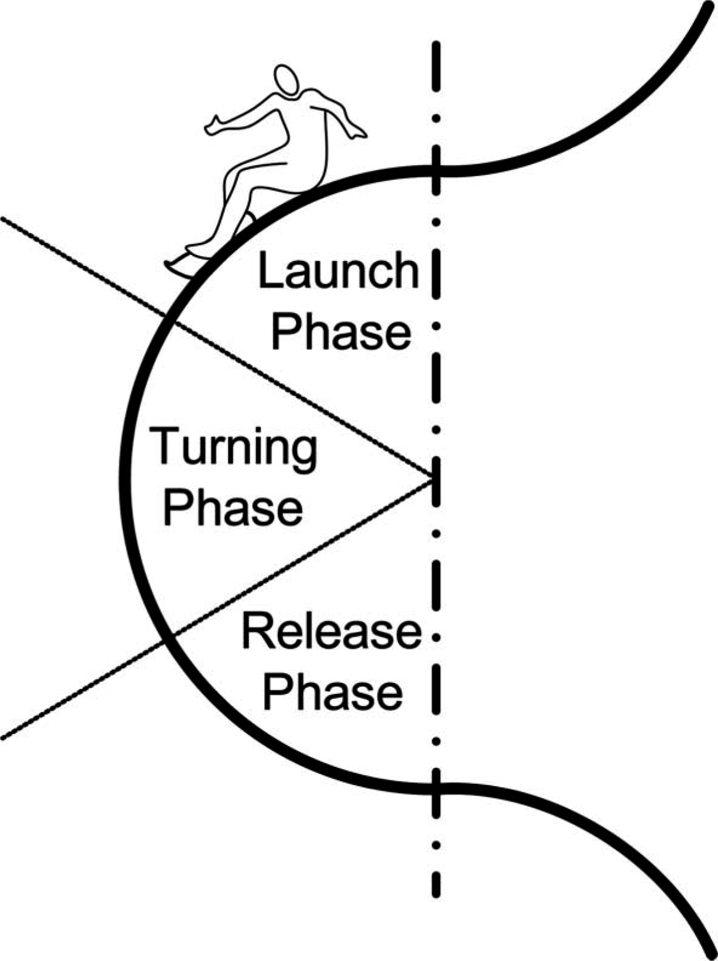
In the turning phase the upper body is kept in the rotated position maintaining the continuation of the turn; however, speed increases due to the slope angle.
The last phase of the turn is the release phase where the upper body is rotated back towards the initial stance posture ready for a new turn to be initiated. The forces acting on a snowboarder and her/his board are generally described by the standard six equations of motion. In order to make the turns efficiently the reaction force between the snow and the board should act perpendicular to the surface of the board (see Figure 6). A snowboarder can change the plantarflexion/dorsiflexion angle of the foot by using supination/pronation of the subtalar joint. By changing this angle the body posture is kept the same, and therewith the position of the COM, but the angle of the snowboard with respect to the slope has changed. This principle is used to control a turn, differentiating between a drifting and a carving turn. A drifting turn is a turn where the boarder of the snowboard drifts out of the initial radius, caused by slipping. A carving turn is a turn without slipping thus the same turning radius during the entire turn is maintained.
Difference between a drifting turn and a carving turn. For a drifting turn the sum of the forces on the COM F
SUM
is not perpendicular to the snow surface and can be divided in to a perpendicular force to the snow F
-SNOW
and a slipping force along the base of the snowboard F
B
. The slipping force F
B
along the base of the snowboard will lead to drifting of the snowboard (shown in the upper figures). If the board is perfectly perpendicular to the sum of the forces on the COM F
SUM
acting on the snow, the snowboard will not slip and results in a perfect carving turn (shown in the lower figures). (A) Frontside and (B) Backside.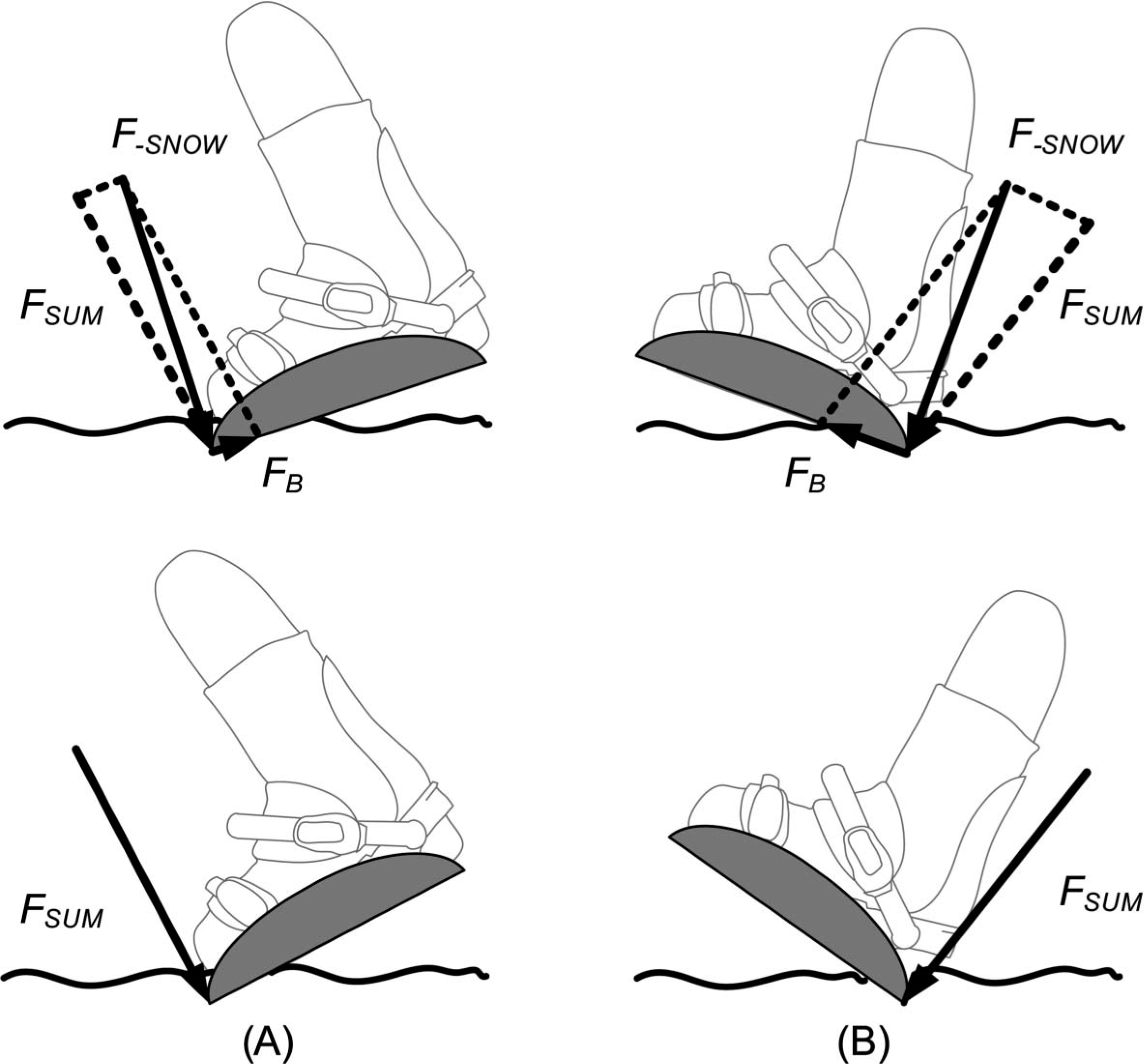
Bio-inspired design
The human ankle was used as inspiration for the design. The passive rotation of the below knee prosthesis can be related to the plantarflexion and dorsiflexion in the human ankle joint.[5] The voluntary control by using supination/pronation can be related to the rotation of the subtalar joint of the human ankle, where a combination of plantarflexion/dorsiflexion and inversion/eversion resembles the motion necessary for the active control.[5]
By using an outward rotation of the knees and hip, the abduction/adduction and inversion/eversion of the newly designed subtalar joint can be controlled. This joint is shaped in such a way that the abduction/adduction and inversion/eversion of the foot is coupled to plantarflexion/dorsiflexion of the foot. Thus a lateral rotation of the upper leg and knee will result in dorsiflexion of the ankle and vice versa a medial rotation of the upper leg and knee will lead to plantarflexion.[6] This method is used in able-bodied snowboarding to voluntarily control the difference between a drifting and a carving turn.
The orientation of the lower leg with respect to the foot can be analyzed in the transverse plane (see Figure 7A). Using Euler rotation matrices to calculate the rotation of the lower leg around the subtalar joint for a human ankle (Figure 7B), leads to approximately the same orientation of the oblique solid black lines in Figure 7A, representing respectively the active rotation of the below knee prosthesis and the subtalar joint rotation in the human ankle.
(A) The superior view of the foot. The orientation of the lower leg with respect to the foot is shown in degrees. Within this figure the summation of the movement of the ankle joint in the prosthesis is shown. The dotted line indicates the transfer from a normal stance of the ankle to the initial stance for snowboarding, where the +3° dorsiflexion and +7° eversion is implemented. The dashed line indicates the passive rotation around the ankle joint earlier discussed, which is +7° plantarflexion and +7° dorsiflexion around the initial stance. The solid lines indicate the rotations of the active control at the end of the passive rotation. Here the combination of the 8° plantarflexion/dorsiflexion, the desired active motion, is combined with the +16° inversion/eversion, the passive motion necessary. (B) The rotation around the subtalar joint axis, shown in the superior view. The bold grey line indicates the foot, the grey line the subtalar joint axis and the black line the rotation of the leg around the subtalar joint axis.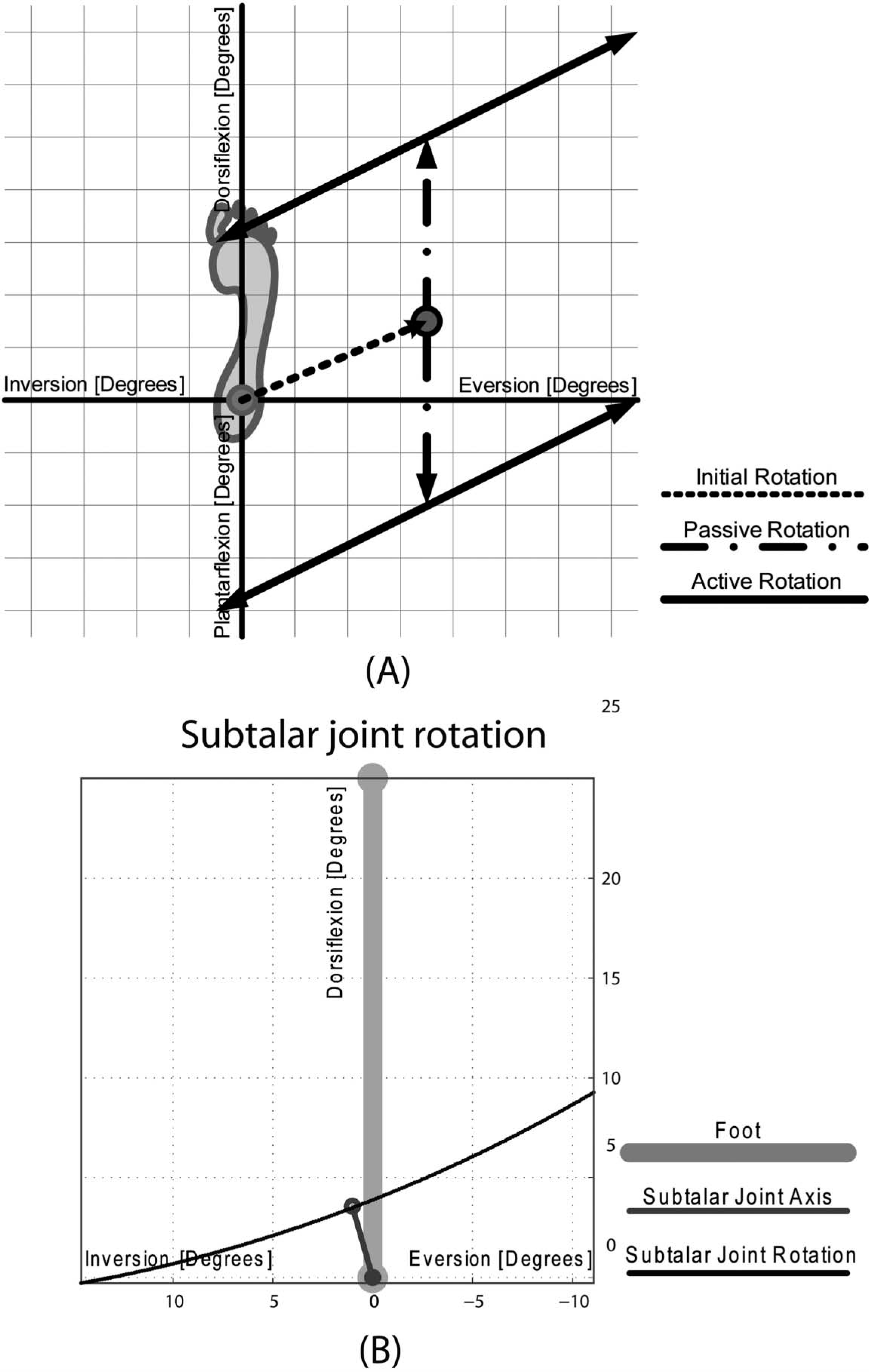
Prototype
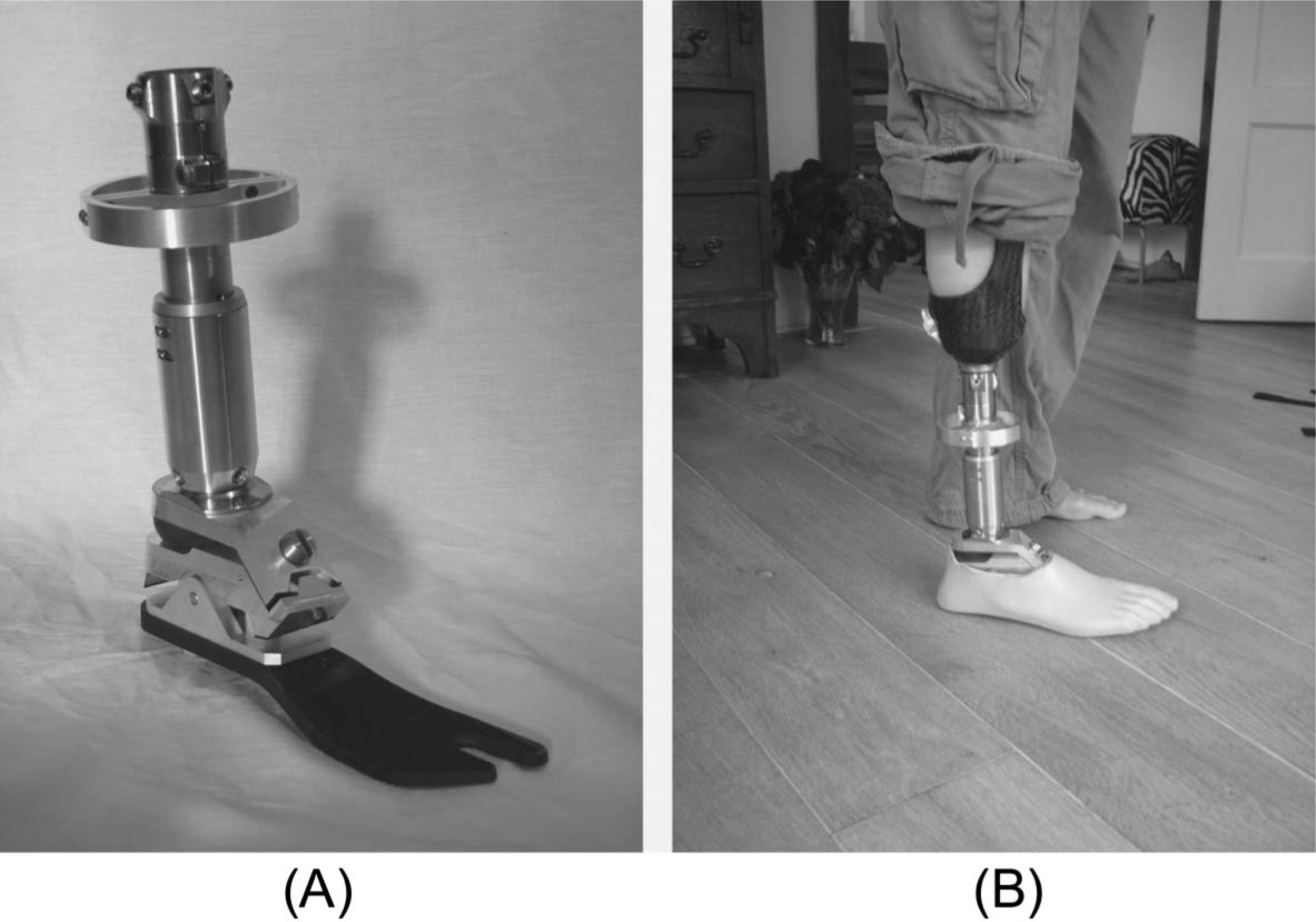
The bio-inspired concept was transformed into a prototype design using standard modular prosthetic components where possible: A Trulife, adjustable clamp adapter (titanium, SCA225) was used for the connection of the prototype to the socket. A slight modification was made to a standard keel of a Seattle carbon lightfoot (SCF, Trulife) to enable its connection to the remainder of the design. Materials for the design specific parts were aluminum, stainless steel and bronze chosen due to their price, specific strengths and machining properties. In Figure 8A the passive rotation of the design is shown, a rotation around the ‘ankle joint’ reacting to external forces only. The ‘voluntary’ rotation, shown in Figure 8B, is a rotation around the newly-created subtalar joint. Voluntary lateral or medial rotation of the upper leg and knee initiates this rotation. In Figure 9 the final prototype is shown after construction. The total weight of the foot in combination with the socket is 1.5 kg.
(A) The grey shaded area in the YZ-plane indicates the passive plantarflexion/dorsiflexion option of the new prosthesis. (B) Active plantarflexion/dorsiflexion is made possible by the incorporation of a ‘subtalar joint’ in the new prosthesis. This joint is a normal hinge joint which axis of rotation points into the negative X-, and into the positive Y- and Z-direction. Voluntary lateral or medial rotation of the upper leg and knee (the action) initiates a rotation around the ‘subtalar joint’ which subsequently results in plantarflexion/dorsiflexion of the ankle. Final prototype after construction and assembly. (A) Final prototype and (B) final prototype connected to the socket and residual limb.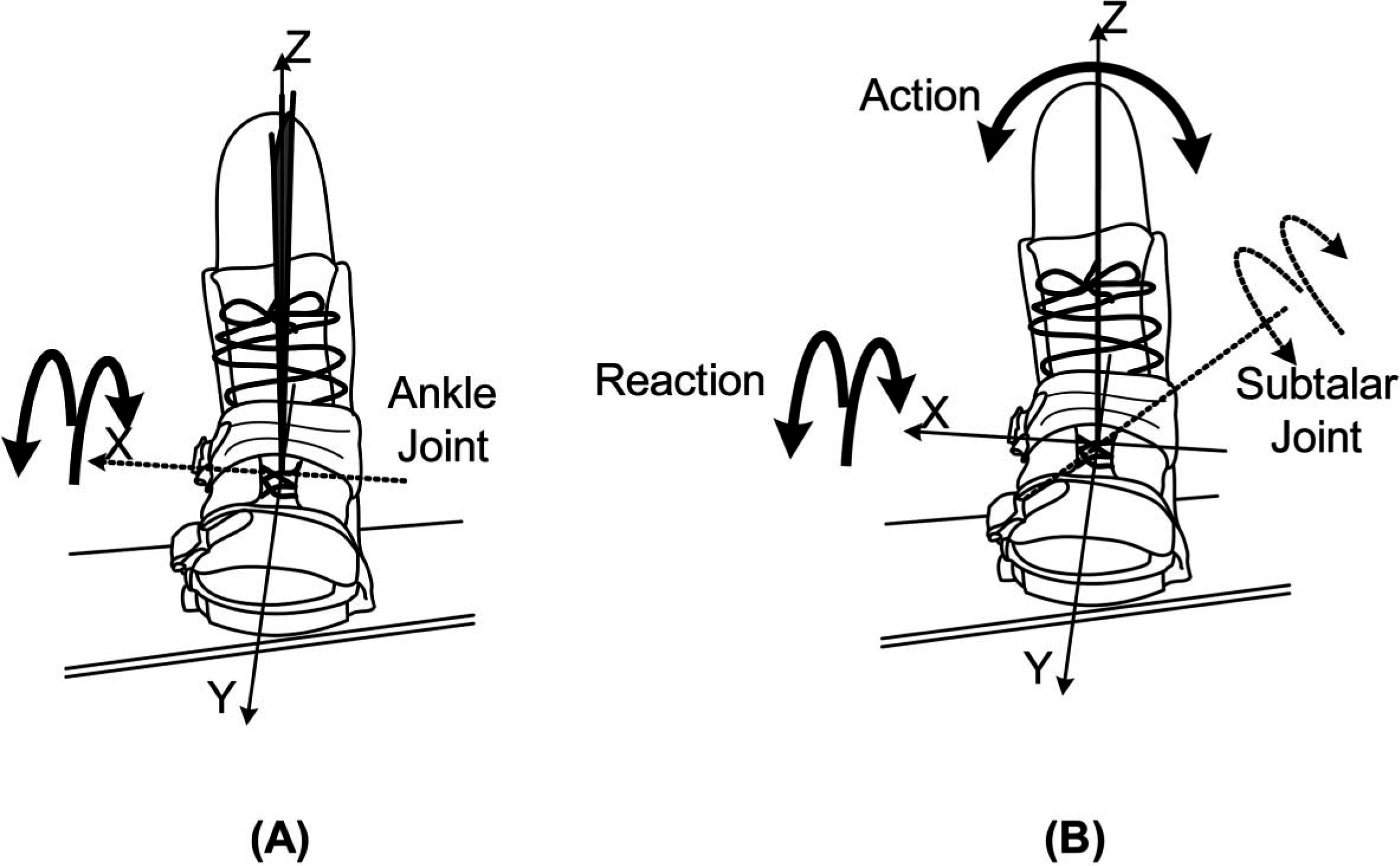
Test results
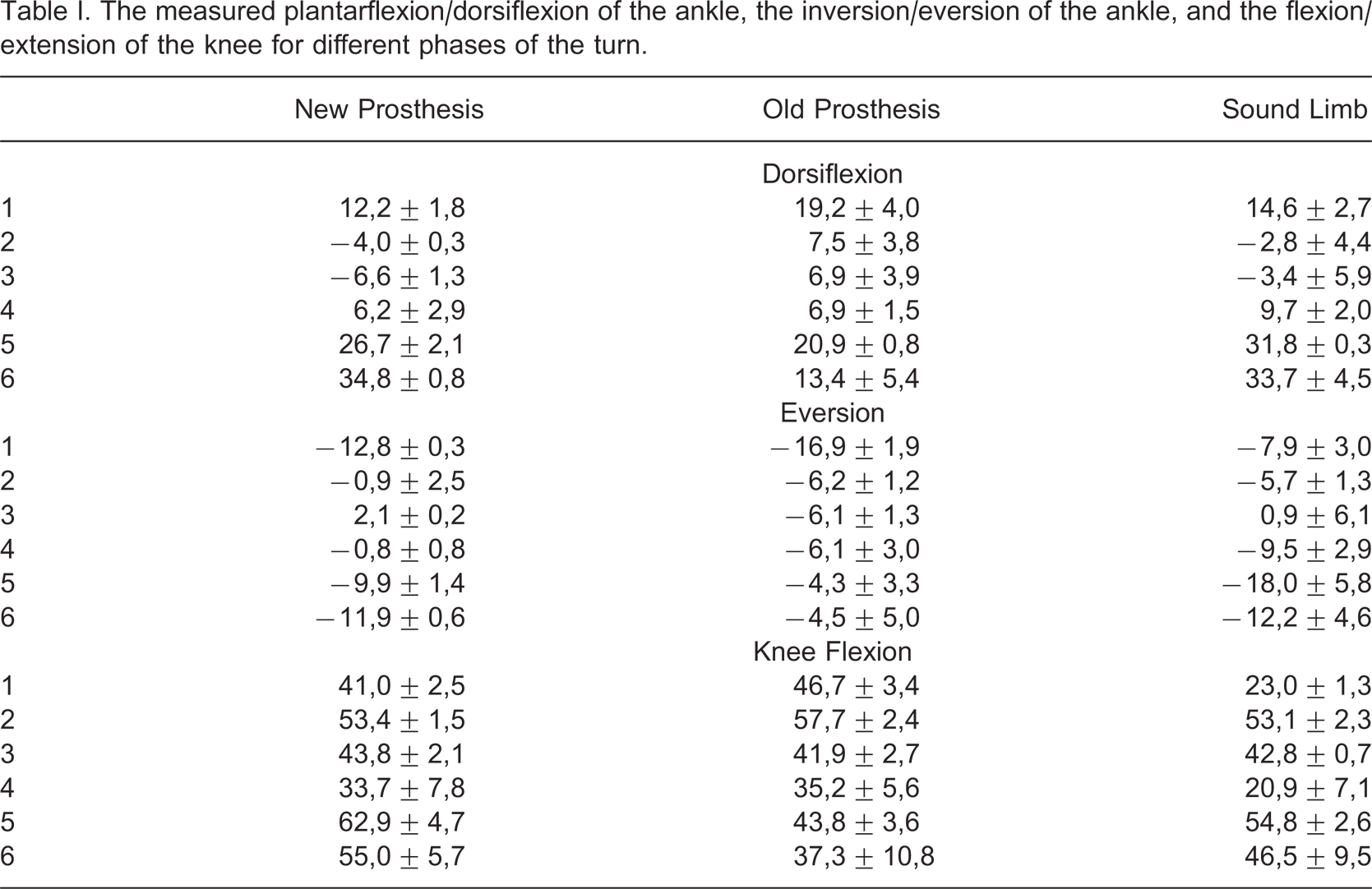
The measured plantarflexion/dorsiflexion of the ankle, the inversion/eversion of the ankle, and the flexion/extension of the knee for different phases of the turn.
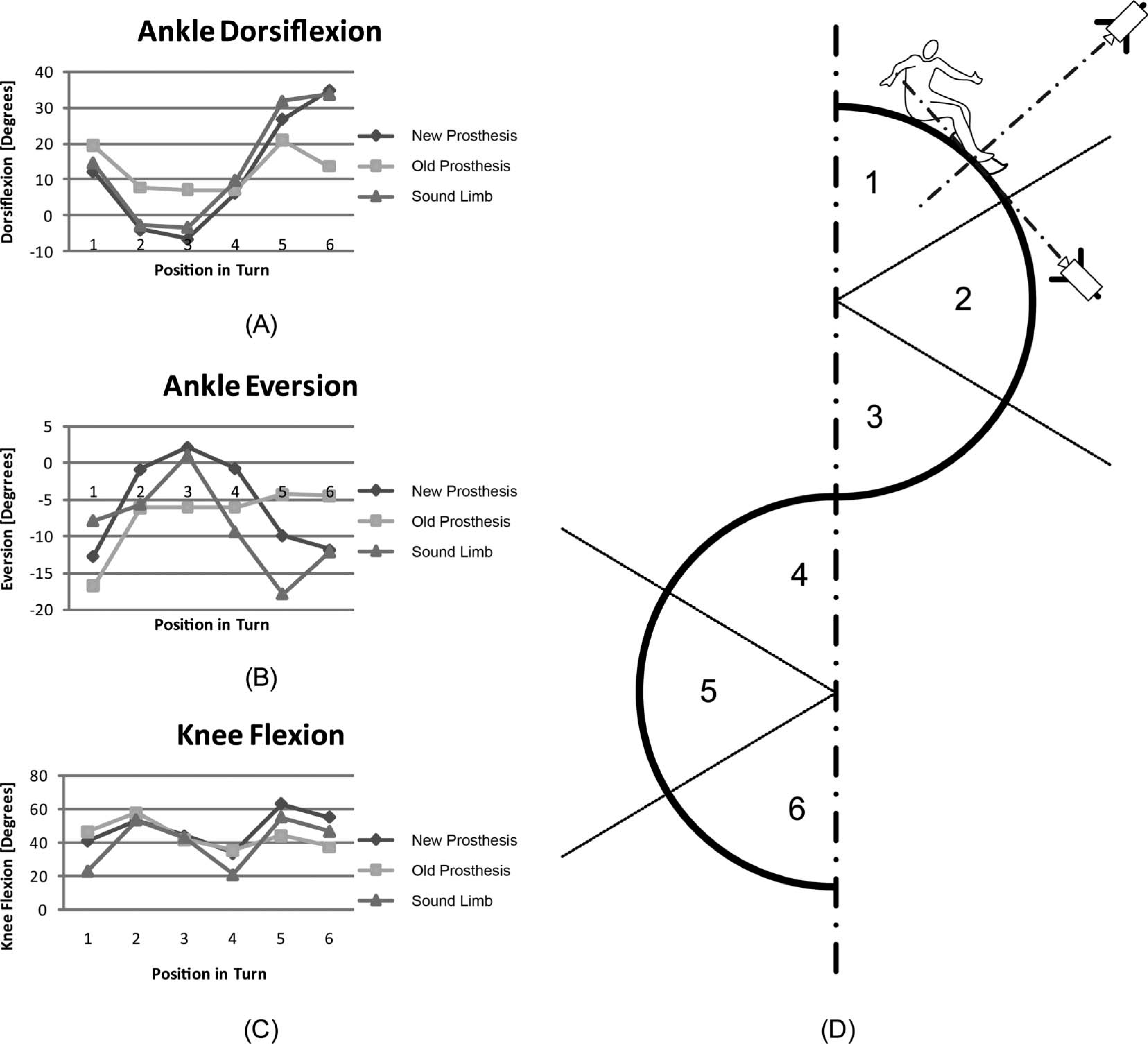
(A) The plantarflexion/dorsiflexion of the ankle, (B) the inversion/eversion of the ankle, (C) the flexion/extension of the knee and (D) the measurements positions in the turn, correlating to the graphs.
Discussion
In the prostheses currently used for snowboarding, the ankle plantarflexion/dorsiflexion has a smaller range of motion than the one achieved with the new design. This smaller range of motion will lead to an asymmetrical turning behaviour, and thus reduces controllability. The increased plantarflexion/dorsiflexion of the new design indicates the extended use of passive rotation.
Lateral rotation of the upper leg and knee will result in pronation of the subtalar joint (used for backside turns), and the medial rotation of the upper leg and knee will result in supination of the subtalar joint (used for frontside turns). The inversion/eversion of the ankle joint during snowboarding indicates the use of the active rotation of the subtalar joint (see Figure 10B). The able-bodied subject and the subject with the new prosthesis showed an increased similarity in active dorsiflexion/plantarflexion indicating that they may use similar techniques to achieve this rotation.
The able-bodied subject, the subject with the new prosthesis and the subject with the old prosthesis had a correlated knee flexion/extension (see Figure 10C). However, the range of knee flexion/extension of the subject with the new prosthesis was larger compared to the range of knee flexion/extension of the subject with the currently used below-knee prostheses and had more resemblance with the range of knee flexion/extension of the able-bodied subject.
Measuring joint angles with video cameras had a limited accuracy. The measurements in this study were used for relative comparison of the joint angles in the different subjects during snowboarding. Because of this limitation, and given the single subject trial, it was difficult to generalize the findings.
Concluding remarks
The overall goal of this R&D project was to improve mobility and control when snowboarding with a below-knee prosthesis. In order to reach this overall goal sub-problems were solved.
When using the new design, the orientation of the lower leg in respect to the foot resulted in a standing posture which was symmetrical, taking the sagittal plane as reference. The ability to dorsiflex, evert and abduct the new prosthetic design led to a stance natural for snowboarding. Added passive rotation in the ankle joint showed a clear change in the plantarflexion/dorsiflexion rotation during the turns for the subject with the new prosthesis, which was comparable to the range of motion used by the able-bodied subject. The ‘voluntary’ rotation of the new subtalar joint enabled additional control of the supination/pronation angle and resulted in a drifting or carving turn. Its design was derived from the use of the subtalar joint for able-bodied snowboarders. The subject had been snowboarding before the amputation, which made it possible to retrieve this technique during the first descents. The measurements of the inversion/eversion of the lower leg compared to the foot showed an increasing use of this rotation for the subject with the new below knee prosthesis when compared to the subject with the traditional below-knee prosthesis. This increased use of inversion/eversion of the lower leg in respect to the foot gave an indication for the use of this new additional joint. On a subjective basis it was noted that the subject was very enthusiastic about the additional rotation possibilities, allowing the ankle to adjust to turns. In particular, the ability to control the subtalar joint, and thus to increase the pressure on the snowboard boarder while turning, seems to make snowboarding like it used to be.