
Abstract
Background and aim:
In the present study, a new approach was applied to design and develop a viscoelastic ankle-foot prosthesis. The aim was to replicate the intact ankle moment–angle loop in the normal walking speed.
Technique:
The moment–angle loop of intact ankle was divided into four parts, and the appropriate models including two viscoelastic units of spring-damper mechanism were considered to replicate the passive ankle dynamics. The developed prototype was then tested on a healthy subject with the amputee gait simulator. The result showed that prosthetic ankle moment–angle loop was similar to that of intact ankle with the distinct four periods.
Discussion:
The findings suggest that the prototype successfully provided the human ankle passive dynamics. Therefore, the viscoelastic units could imitate the four periods of a normal gait.
Clinical relevance
The novel viscoelastic foot prosthesis could provide natural ankle dynamics in a gait cycle. Applying simple but biomechanical approach is suggested in conception of new designs for prosthetic ankle-foot mechanisms.
Background and aim
Considering the entire human ankle joint biomechanics is essential for designing of biomimetic ankle-foot prostheses that ideally replicate the lost functional ability in lower limb amputation. 1 The conventional prosthetic feet such as SACH (Solid Ankle Cushion Heel) and single-axis feet, made of wood and rubber, have been prescribed to restore the walking ability to the individuals with amputation. 1 Considering the higher levels of performance has resulted in development of the energy-storing-and-returning (ESR) feet. These feet store and release energy during a gait cycle. 1 Although the transtibial amputees feel more comfort with the ESR than conventional feet, clinical studies have indicated that the ability of ESR in replicating the natural ankle biomechanics is still limited. 1 This could contribute to kinetic and kinematic gait deficiencies in the transtibial amputees.2,3
This has led the researchers to develop advanced prosthetic feet which imitate the biomechanics of intact ankle.1,4–8 This has been explored by plotting ankle moment versus its angle that is thought to be useful for the new prosthetic feet concepts as it can reveal ankle function.1,4,9,10 For example, BiOM (iWalk, Inc., USA) is the first active prosthetic ankle foot in the market that includes motor and control algorithm. This foot generates powered push-off in late stance. Viscoelastic ankle-foot prostheses, such as the Echelon foot (Chas A Blatchford & Sons, Ltd, UK) and The Motionfoot (Motion Control, Inc., USA), incorporate adjustable hydraulic unit with the ESR feet and claimed to provide a damped range of ankle motion. The Proprio Foot (Ossur, Reykjavik, Iceland) is a quasi-passive microprocessor foot that adjusts the ankle angle in response to the changes in surface or activity. Although these devices are very promising and shown to reproduce natural ankle biomechanics, they are not widely available presently. This might be due to the complexity of the mechanisms, the need of the power source, and their high cost.
However, recent studies have suggested that the ankle biomechanics can be replaced by more simple passive mechanical systems in slow to normal walking speeds and an active energy source is needed in faster speeds.9,11 Hansen et al. 9 showed that human ankle moment-angle curve in stance phase displays narrow hysteresis loop at normal walking speed. Takahashi and Stanhope 11 also suggested human ankle-foot system showed work ratio not greater than 1.0 in normal walking speed. Therefore, it is suggested that an adjustable spring-damper mechanism may be beneficial at slow to normal walking speeds.
On the basis of these phenomena and to overcome the mentioned limitations of advanced prosthetic feet, viscoelastic ankle-foot prosthetic prototype was developed to follow the human ankle biomechanics (moment–angle loop). The prototype incorporated two viscoelastic units to provide damped range of ankle motion in the defined periods of a gait cycle.
Technique
Design concept for the viscoelastic prosthesis
The human ankle-foot function based on the moment versus ankle angle curve was considered in designing the prosthesis. In a complete gait cycle (stance and swing), this curve can be divided into four distinct periods (Figure 1).1,4,9,12
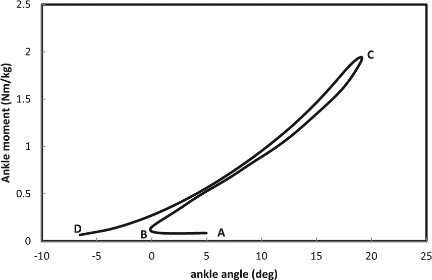
Typical intact ankle moment versus angle loop in stance phase of walking. The curve was divided into four periods: AB: controlled plantarflexion (CP), BC: controlled dorsiflexion (CD), CD: powered plantarflexion (PP), and DA: swing period.
Therefore the prosthesis was considered to follow the functions as below:
Controlled plantarflexion (CP) period. The prosthesis should absorb the initial heel contact forces and control the rate of foot slap. This was replaced by a damper in parallel with a low-stiffness return spring.
Controlled dorsiflexion (CD) period. The prosthesis should save the energy and provide the stable base for forward rotation of tibia around the foot by a high-stiffness spring.
Powered plantarflexion (PP) period. The prosthesis should return the stored energy in CD phase and provide the push-off for the forward propulsion.
Swing phase (Sw). The aim of the prosthesis in this period was to return the foot to the neutral position for the next step by a spring-damper mechanism.
Mechanical design
SolidWorks model and the photograph of the developed prototype are shown in Figures 2 and 3. The developed prototype had total weight of the 4.0 kg, height of 37 cm, and medio-lateral and anterior–posterior widths of 8 and 30 cm, respectively.
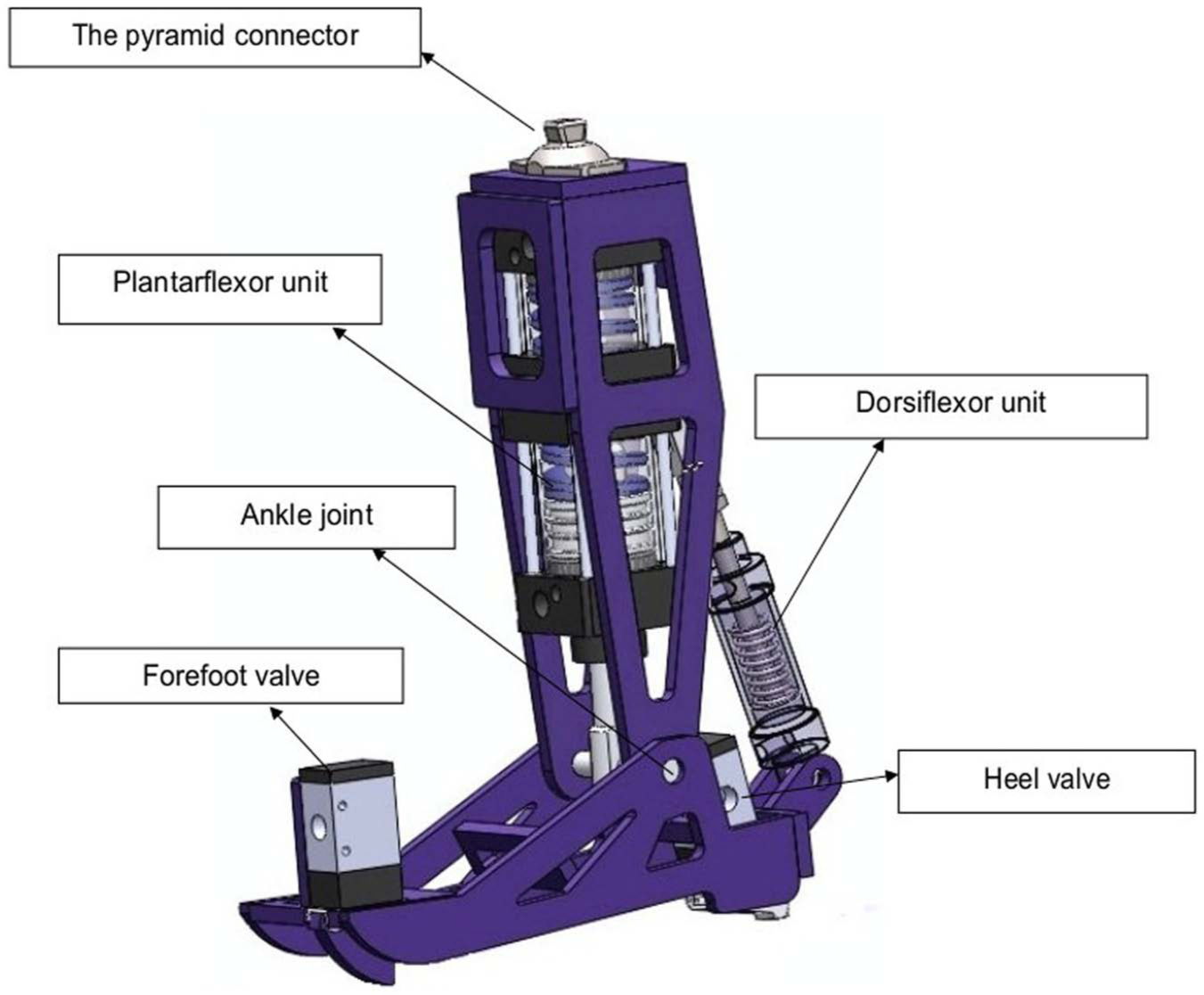
SolidWorks model of the prototype.
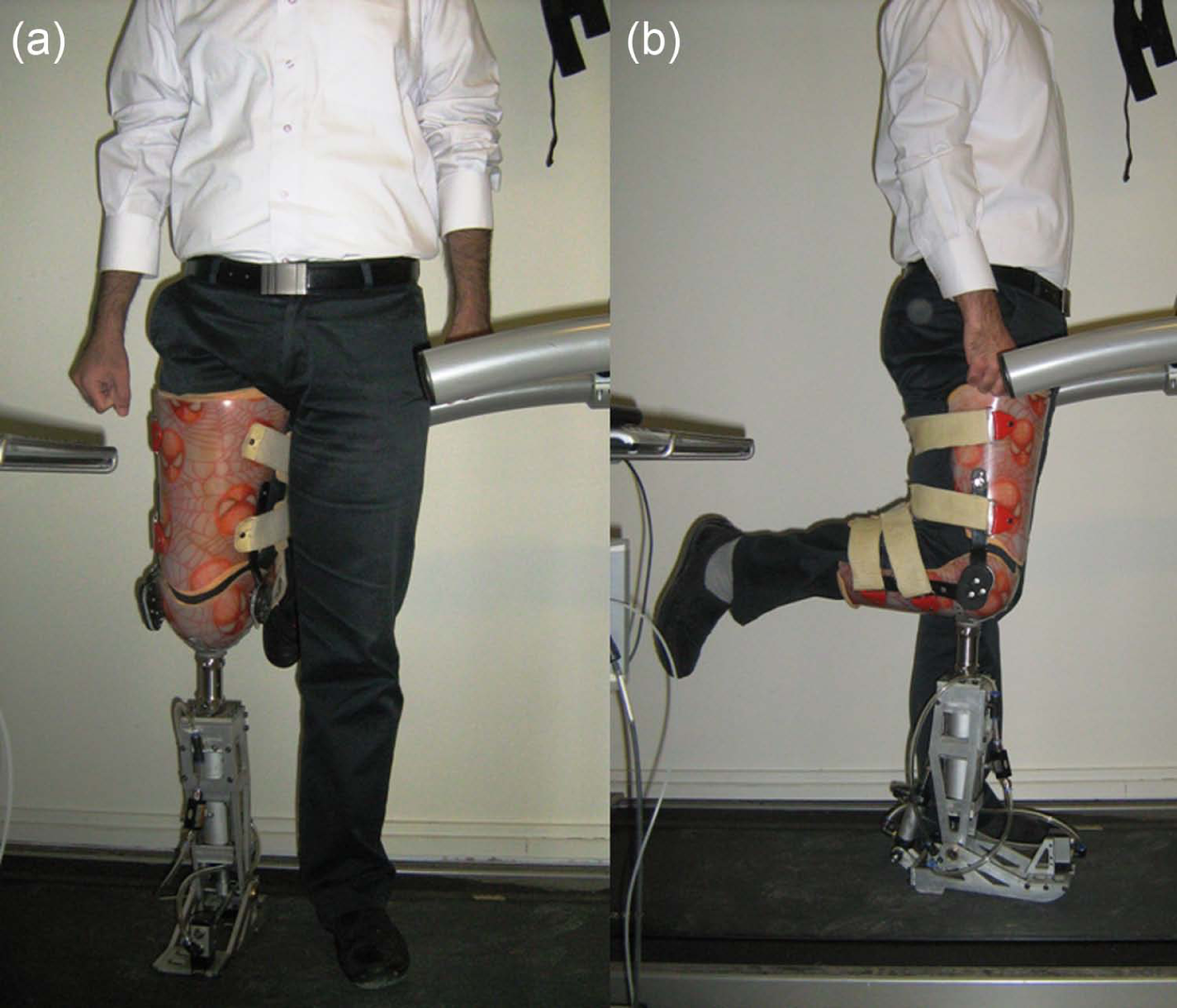
Testing the prototype with the amputee gait simulator adaptor: (a) frontal view and (b) sagittal view.
As shown in Figure 2, the mechanical design of the prosthesis consisted of ankle joint mechanisms and shank and foot components. The shank and foot components of the prosthesis were formed by aluminum alloy. The pyramid connector was attached to the upper plane of the shank for socket connection. Ankle joint mechanisms comprised two cylinder and piston assemblies to be engaged in the four mentioned intervals (i.e. CP, CD, PP, and Sw).
The conceptual spring-damper mechanism described earlier for CP and Sw period was replaced by dorsiflexor unit, which was a pneumatic cylinder consisted of a piston rod and a small returning spring. The purpose of the spring was to save the energy in CP and supplement it for swing period to replace the foot in the neutral position. The cylinder was connected to the control valve on the forefoot which was in the open position when unloaded and air was passed through the unit. When the handle beneath the valve was loaded by forefoot contact, the valve was operated, inlet air into the unit was blocked, and the unit was stopped in early stance. At the beginning of the swing and by unloading the forefoot valve, the unit was enabled again, and the small compressed spring returned the foot to the neutral position.
The conceptual spring-damper mechanism described earlier for CD and PP phases was replaced by the plantarflexor unit which incorporated a pneumatic cylinder consisted of a piston rod and a compression spring to save the energy in CD and supplemented it for PP (push-off period). The unit also had a pressure control valve on the heel which permitted the adjustable damping.
Experimental evaluation on a healthy subject
The preliminary test of the stability of the design and the mechanism was performed on an able-bodied male subject. It was thought that the healthy subject was prone to the lesser risk of fall or injury during the test of a new prototype. The adaptor was fabricated by an experienced orthotist based on the fabrication technique of the common knee brace to simulate the amputee walking. This device allowed the lower leg to be flexed in 90° of flexion. The adaptor was attached to the pyramid connector on the upper plane of the prosthesis (Figure 3). The participant provided written informed consent approved by the University Ethics Committee.
Gait analyses were performed in a gait laboratory with five infrared cameras (Vicon 460, Vicon Motion System Ltd, UK) and two force plates (Kistler Instrument AG, Switzerland). Kinetic and kinematic data were collected at a rate of 100 Hz. Reflective markers were placed on the anatomical landmarks. The participant was initially instructed to walk with the prosthesis at self-selected normal speed. After getting used to the test, at least six trials were captured.
To verify the performance of the prototype, the moment–angle relation of the prosthetic ankle was plotted which is shown in Figure 4. The results showed the prosthetic ankle moment–angle loop confirmed the intact ankle behavior. Distinct intervals including CP, CD, PP, and Sw could be identified from the loop similar to that of intact ankle. The prosthetic ankle started stance phase with CP, followed by CD. At terminal stance, the prosthesis showed plantarflexion prior to the swing phase.
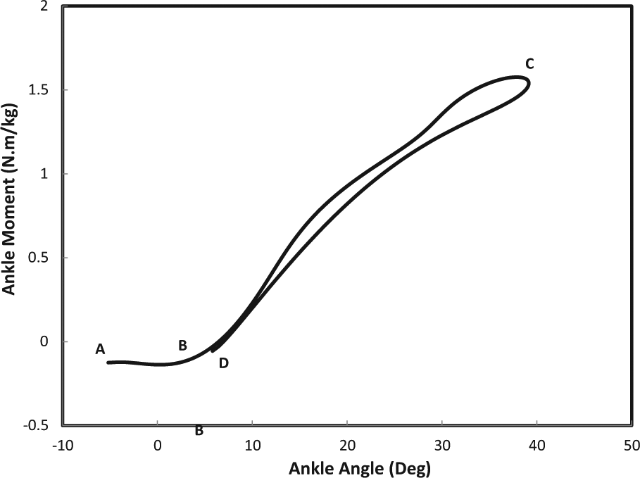
The ankle moment versus angle loop of prosthetic ankle. The curve was divided into four periods: AB: controlled plantarflexion (CP), BC: controlled dorsiflexion (CD), CD: powered plantarflexion (PP), and DA: swing period.
Discussion
In this article, a new approach was applied to design and develop prototypical viscoelastic ankle-foot prosthesis that imitates the moment–angle loop of the intact ankle in normal walking. Current researches in ankle-foot prosthesis field have mainly focused on advanced prostheses incorporating electronic parts.
To the authors’ knowledge, the Echelon foot (Chas A Blatchford & Sons, Ltd, UK) and the Motionfoot (Motion Control, Inc., USA) are the only passive viscoelastic prostheses available in the market. These feet have the hydraulic unit that led in damped range of ankle motion. This could lead to loss in the amount of saved energy in mid stance and thus reduce the restoring ability of such devices. However, we presented a passive viscoelastic prosthesis that incorporates two spring-damper units. Each unit was designed to provide the damped range of ankle motion in a specific interval (i.e. energy damping in the initial stance, energy storing in mid stance, and energy restoring in late stance and bringing foot to a neural position in swing phase).
The preliminary results showed that the general shape of moment–angle curve confirmed that of intact ankle. The results more approved the notion that viscoelastic prosthesis can replicate the overall dynamics of intact ankle joint in slow to normal walking speed.
The dorsiflexor units succeeded in providing a damped range of CP at the beginning of stance phase. In CD period, the plantarflexion unit of the prosthesis provided a stable angular movement of shank around the foot by preventing rapid heel-off. In PP, the rapid arch of plantarflexion was seen which indicated the release of the energy stored in CD. The compressed spring of the dorsiflexor unit returned the foot to the neutral position at swing phase.
However, these preliminary results revealed several aspects which should be considered in the next prototype. At this stage, the biggest plan is testing the prototype on an amputee. This limitation is considered in the next generation by improvement both in the material and the mechanism and by reducing the mass and the height of the prosthesis.
Key points
The viscoelastic prosthesis could successfully replicate the passive dynamics of intact ankle.
The dorsiflexor unit of the prosthesis could provide a damped range of CP similar to that of normal ankle.
The plantarflexor unit could store energy in CD and release it in PP phase.
The dorsiflexor unit could bring the ankle in neutral position in Sw phase.
Footnotes
Acknowledgements
The authors would like to thank Abdollah Shamloo for his valuable help in mechanical design and fabrication of the prototype and the Iran National Science Foundation, Tehran, Iran for the financial support. Contribution of Hoda Nabavi, Department of Ergonomics, University of Social Welfare and Rehabilitation Sciences, Iran, in data collection is appreciated. Lastly, we would also like to thank Farhood Saeed Ershadi, for helping in fabricating the adaptor.
Declaration of conflicting interest
The authors report no conflicts of interest.
Funding
This research was supported by the Iran National Science Foundation, Tehran, Iran.