
Abstract
Background:
Many finite element investigations have been made in the field of lower limb prosthetics; however, friction between bone and soft tissues as a boundary condition has not been considered.
Objectives:
To establish whether the change in the contact boundary condition between bone and soft tissues in a transfemoral amputee affects the stress-strain state on the residual limb.
Study Design:
Finite element analysis comparison.
Methods:
Finite element models of four transfemoral amputees were developed. In these models the socket, soft tissues and femur were included and two simulations were made for each model, in one of them the interaction between bone and soft tissues was defined as tied (there is no relative displacement between surfaces) and in the other it was defined as a friction boundary condition.
Results:
The von Mises stress and strain peaks are higher when the friction definition is used than for tied contact definition. The distribution pattern of stresses and strains also change when the contact definition varies from tied to friction.
Conclusions:
It was concluded that the friction between bone and soft tissues have a significant impact on the results of finite element models of lower limb prosthetic systems, and therefore in its predictive capabilities.
Clinical relevance
Understanding the bone-soft tissue interaction can lead to more realistic and accurate finite element models used to predict the stress-strain state in the residual limb of prosthetic users and therefore predict the occurrence of deep tissue injuries.
Background
The flexibility and power of the finite element (FE) method make it an invaluable alternative to develop models related with in vivo studies in the field of biomechanics, where the analysis of the actual processes can sometimes be very difficult. The use of the FE method to simulate the human body parts, processes and its interactions with the environment has been increasing; however, usually specific models have to be developed.1–3 This specificity makes these models incompatible between them or impossible to use one of them to simulate different conditions. 4 This situation obliges the new developers to start their own models from zero instead of building over pre-existent ones. The same situation happens when the study of prosthesis and its interactions with the human body is done, where there is no general model to use, and it is necessary to develop a new model for each patient where the stress-strain state has to be obtained.
One of the main areas of interest in the FE studies of prosthesis, specifically in the lower limb, is the pattern distribution and magnitude of the stresses in the socket-stump interface and inside the stump, because there is a direct relation between these factors and the health of the tissues involved.5,6
For stump and socket interaction many FE models have been developed, most of them for transtibial amputees,7–19 but only two are known to be for transfemoral amputees. 20 Some of them were done in 2D6,17 while others used 3D7–14,16,18–20 representation of the geometry. The boundary conditions were also applied in different ways, in some cases the contact definition between socket and stump was declared as frictionless8,18,20 while others defined it as friction contact.7,9–14,16,19 Mechanical properties of the soft tissues, bone and socket were defined mainly as elastic, linear and isotropic,7,9–12,16,18 but there were some cases in which the socket,6,19 the bone13,19,21 or even both 19 were defined as rigid solids. The initial overclosure between socket and stump was addressed and solved in different ways: (1) the most common practices were automatic adjustments of the overclosure, where the software deforms the stump to avoid the overlap between the elements of the stump and the socket (or liner)7,12,14,16; (2) non automatic radial displacement of the nodes in the stump to fit it inside the socket.6,9,10
Usually, the load was applied over the bone6,7,9,10,17,19 but Ling et al. 11 replaces the load by a bone displacement.
In all models, the surfaces in contact between bone and soft tissue are tied, meaning that there is no relative slippage between the nodes of the bone surface and the nodes over the internal soft tissue’s surface, which is known as a tied contact definition.6–20
The simplification of the interaction between bone and soft tissue as tied does not take into account either the shear stress due the friction at bone-soft tissue contacts or the greater pressures generated in the distal zone of the residual bone, therefore is not an accurate representation of the actual interaction where some friction and slippage occur. The prediction of deep tissue injuries (DTI)29 and others pathologies using the FE method requires a more realistic approach to the bone-soft tissue interaction.
Thus, our aim was to identify whether the boundary condition has strong effects over the stress-strain state of the stump soft tissues or not. Specifically when tied and friction boundary conditions were used.
Methods
Four male patients with unilateral transfemoral amputation were selected. Table 1 shows their general information. All of them were relatively active in their daily life and did not have any additional physical, vascular, neurological or psychological condition that could alter or modify the results of the analysis. The patients used a total suction socket with non-distal end support, a solid ankle cushioned heel (SACH) foot, and mechanical monocentric knee prosthesis. They did not use a liner or a sock because it interferes with the airtight seal. According to the ethics committee of the National University of Columbia, a proper informed consent was provided by the patients before the procedure started.
Patient characteristics.
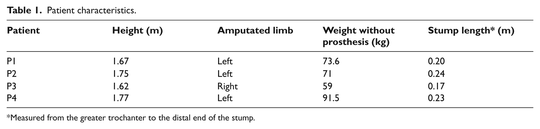
Measured from the greater trochanter to the distal end of the stump.
Development of the model
Each model was composed of three submodels: socket, stump and residual femoral bone.
While the patient was standing up, a prosthetist made a cast that was used in the fabrication of a plaster positive of the socket and of the stump. After these solid elements were made, a 3D laser scanner was used to obtain a digital representation of the socket and stump. To complete the model, the 3D residual femur model was developed from a computed tomography (CT) scan using an image processing software (Invesalius V3).
To guarantee a precise relative position between the socket, soft tissue and the residual bone, some marks were made over the plaster positive of the socket and the stump at specific location as close as possible to the greater trochanter and ischial tuberosity. Then, matching those marks with the CT image information, the three different solids (socket, residual bone and a bulk representation of the remaining soft tissues) were aligned in an anatomical and well defined relative position using Solid Works 2009 (Dassault Systèmes, France). The resulting assembly was exported to the FE analysis software ABAQUS V6.9.2 (Figure 1), where two different simulations took place for each model, corresponding to both types of contact formulation between bone and soft tissues (tied and friction). Linear tetrahedric elements were used and they range from 35,000 to 221,000, according to the stump’s geometry of each patient.
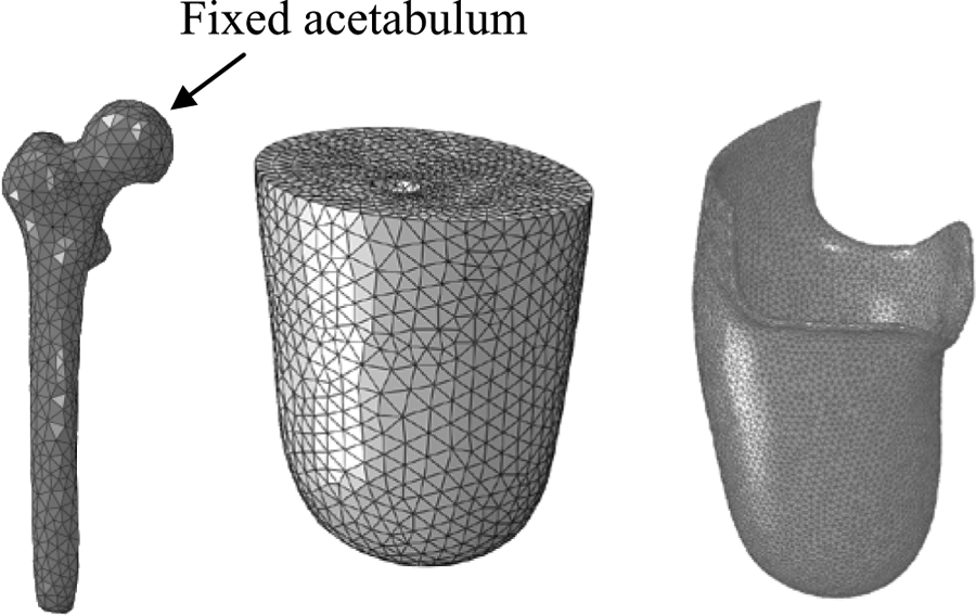
Discretization of the models and fixed boundary condition.
Boundary conditions
The femur was fixed in the surface of the head covered by the acetabulum (Figure 1), where the three degrees of freedom corresponding to displacement were restricted. The loads over the stump were applied in two steps. First it was put under a pre-load, which corresponds to the deformation caused by the donning of the socket. The penalty method was used in the contact, where the normal interaction between socket and stump was defined as HARD (there was no penetration) and in tangential direction it was defined using a friction coefficient of 0.415. 22
During the second step, the load was applied to the socket in its distal surface and it represents the forces transmitted through the prosthesis during the bipedal static stance. These loads were patient specific and were assumed to be equal to half the weight of the patient in vertical direction. The time of application for these loads was 100 ms 17 and the load was defined as distributed over the area of contact between the socket, and the rod which joins it with the rest of the prosthetic device.
Accordingly with the objective of this study, keeping external boundary conditions, material definitions, loads and meshing rules fixed; two sets of simulations were developed changing only the contact boundary condition between bone and soft tissue. In one of them the tangential interaction was defined as tied, while in the other it was defined as friction, with a friction coefficient of 0.3. 23 The normal interaction was defined as HARD (no penetration) for both.
Material properties
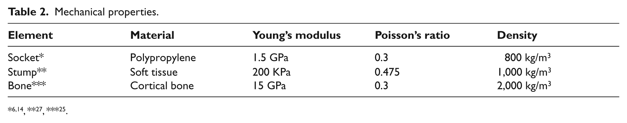
For soft tissues a viscoelastic representation may be adequate as used by Portnoy et al. 24 However, there are no measurements on the empirical constants used for the strain energy function of the viscoelastic formulation. Thus, in order to be able to compare our results, all materials used in this analysis were defined as elastic, linear, homogeneous and isotropic, according to the definitions used by other authors.6,7,9–12,14,16,18,25 Table 2 shows the mechanical properties used for all materials.
Mechanical properties.
Finite element analysis
The simulations of these models were made using the explicit module of ABAQUS V6.9.2, because it has better performance than the quasi-static or static algorithms when there are kinematic nonlinearities caused by large deformations and the loading time has influence over the results.
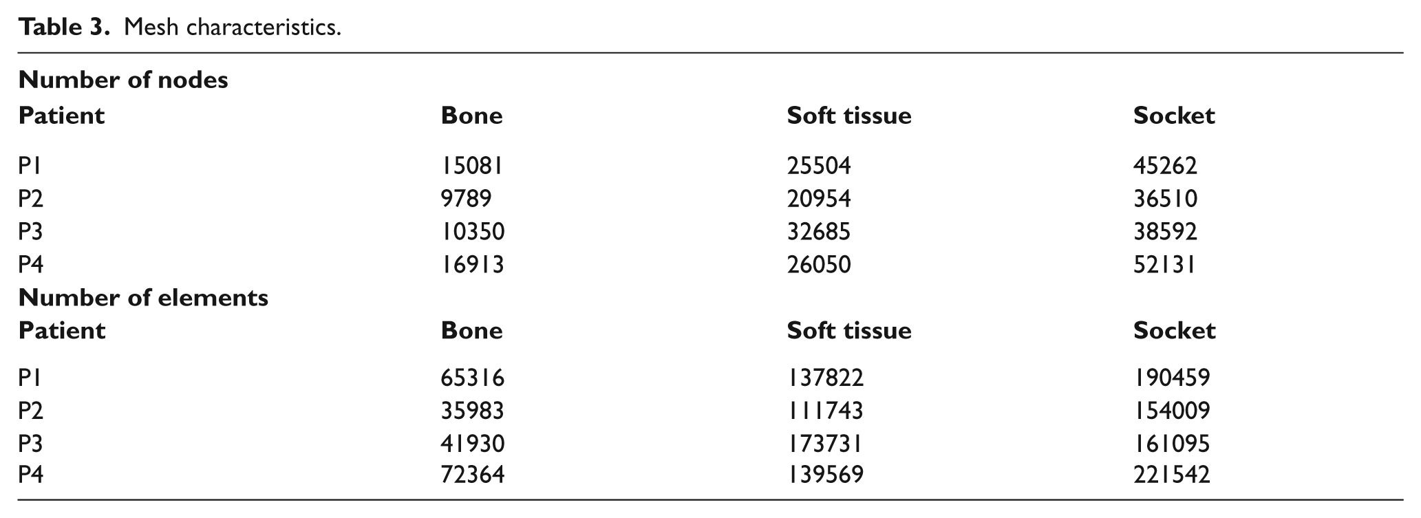
Due to the complexity of the models it was not possible to build a structured mesh, instead of that, an automatic algorithm was used for meshing. The type of element was linear tetrahedric with four nodes (C3D4). The mesh dimensions for elements were 0.005 m for the soft tissue and 0.003 m for the socket and the femur. The quantity of nodes and elements used for each model and patient can be seen in Table 3.
Mesh characteristics.
Results
For models developed under tied boundary condition (Figures 2a, 2c, 2e and 2g) the maximum von Mises stresses are located in the proximal zone of the stump, specifically at the interface of bone-soft tissues. The magnitude of the peak stress decreases along the proximal-distal direction.
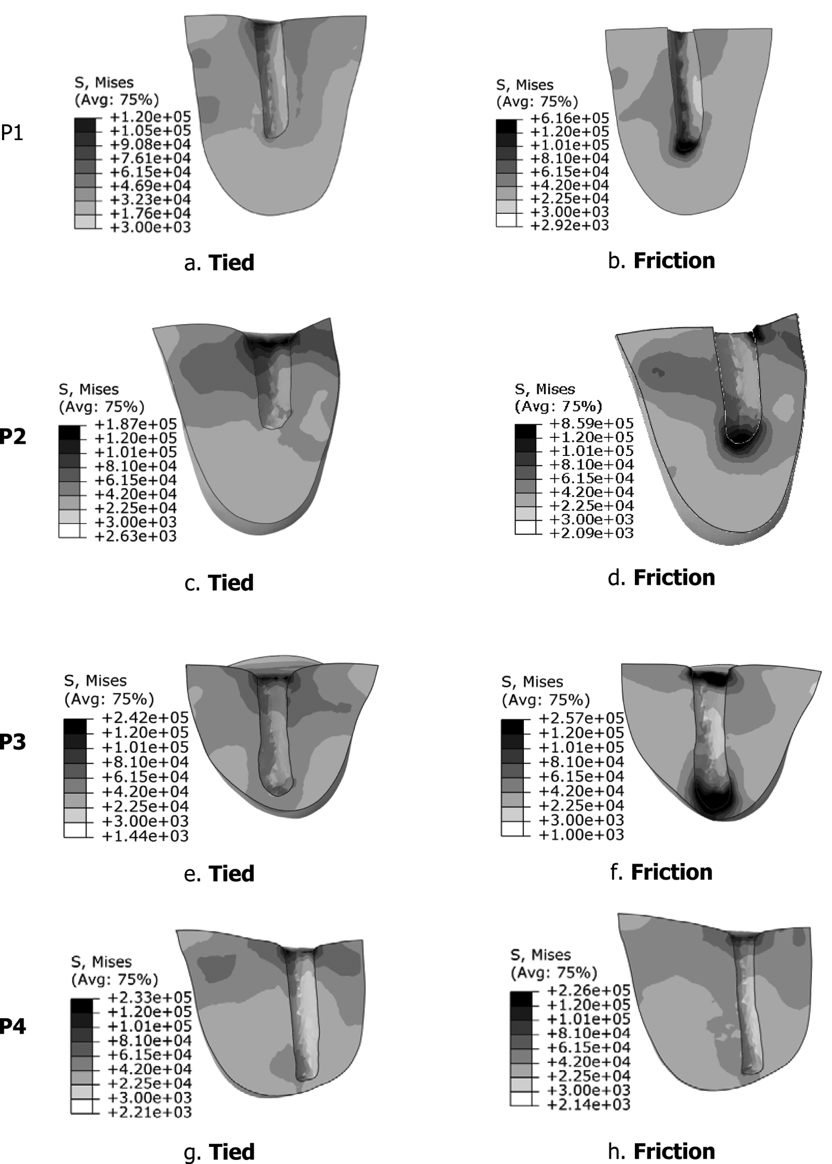
Von Mises Stress distribution (Pa). Tied: P1 a, P2 c, P3 e, and P4 g. With friction: P1b, P2 d, P3 f, and P4 h.
For models with friction boundary condition formulation (Figures 2b, 2d, 2f and 2h) there are two zones where the maximum von Mises stresses are located, the proximal and the distal zone of the interface bone-soft tissue.
In order to show the variation of the stresses’ magnitude, two graphic charts were made to make a comparison: Figure 3a shows the peak von Mises stress for each patient and type of interaction (tied or friction), while Figure 3b presents the mean von Mises stress for each patient and type of interaction.
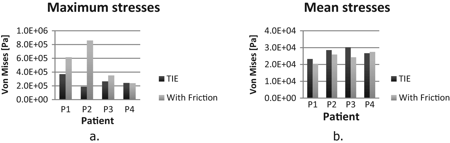
Peak von Mises stress (a) and Mean von Mises stress (b).
For all patients, except P4, there is an increase in the maximum von Mises stress value when the definition of the contact between bone and soft tissues changes from tied to friction (Figure 3a). Patient P2 has the largest variation, almost 600 kPa. For patients P3 and P4 the peak von Mises stress has the same order of magnitude for tied boundary conditions, while P3 increases with the friction definition, P4 remains almost equal.
The mean von Mises stress was calculated as the mean of all the elements of the soft tissue, and as can be seen in Figure 3b, the variation of the mean stress was consistent between patients, it decreases in P1, P2 and P3 and these variation range from 2.4 kPa in P2 to less than 6 kPa in P3. For patient P4 the mean stress increases less than 1 kPa.
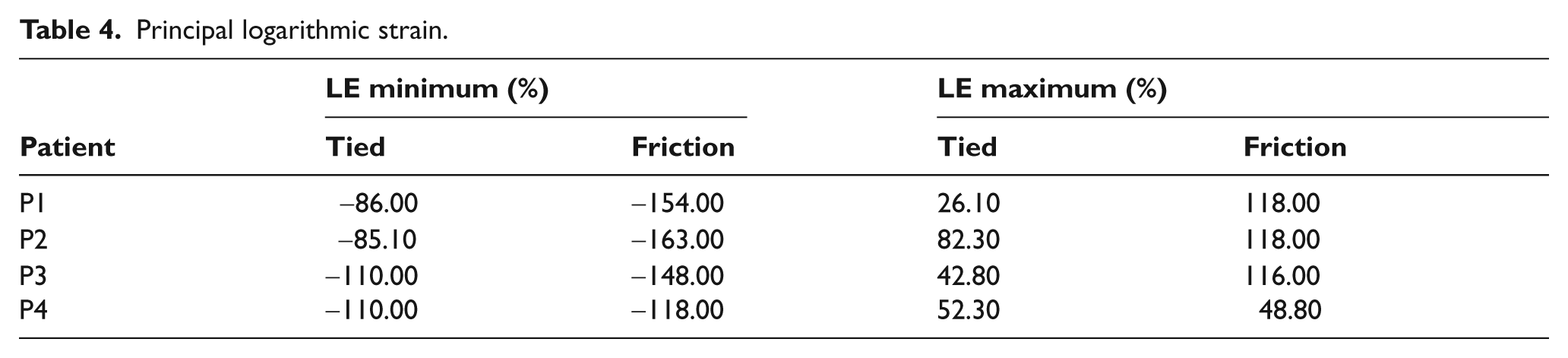
Table 4 shows that there is a significant increase in the peak principal strain values when the contact definition changes from tied to friction in all patients, this happens for tensile strains as well as for compressive strains. The peak values are 163% in tensile and 118% in compressive. Both peaks are developed under friction boundary condition for patient P2.
Principal logarithmic strain.
Figures 4 and 5 depict the respective pattern distribution of maximum principal logarithmic strains and minimum principal logarithmic strains. It can be seen that the patterns of strains change consistently with the stress patterns shown in Figure 2. The peak strains are grouped in the proximal zone of the soft tissues for the models with the tied contact definition (Figures 4 and 5), while in the models with the friction contact definition, the peak strains are located both in the proximal zone of the soft tissues and in the distal end of the bone-soft tissue interface.
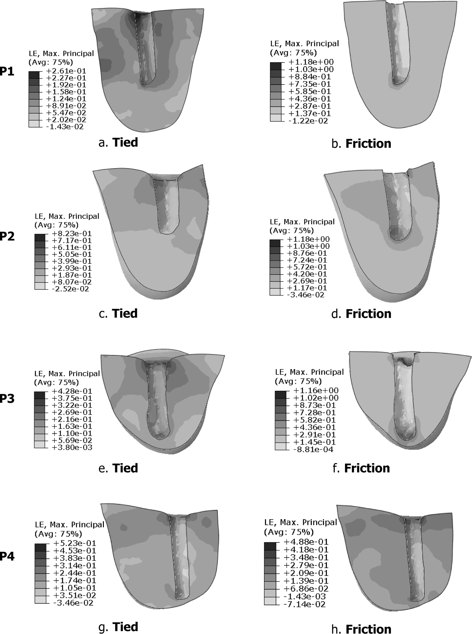
Maximum principal logarithmic strain distribution. Tied: P1 a, P2 c, P3 e, and P4 g. With friction: P1b, P2 d, P3 f, and P4 h.
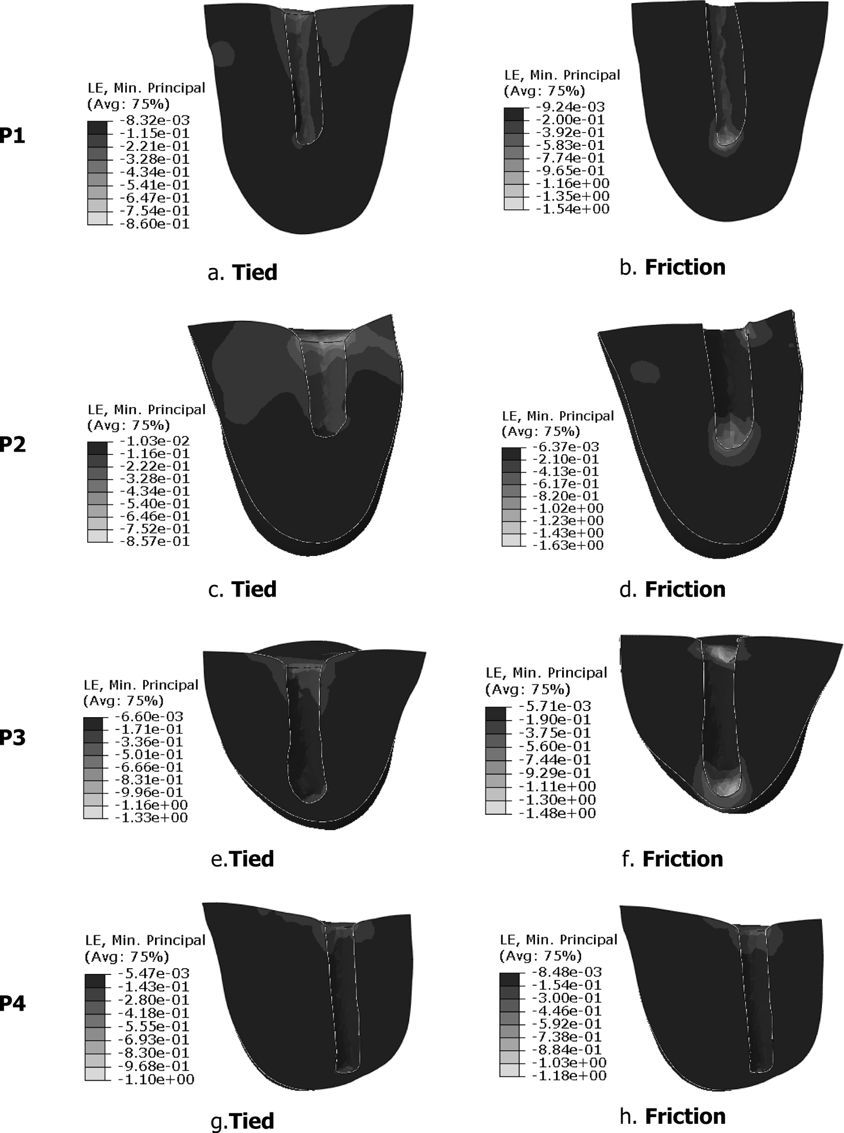
Minimum Principal Logarithmic Strain distribution. Tied: P1 a, P2 c, P3 e, and P4 g. With friction: P1b, P2 d, P3 f, and P4 h.
The mean compressive and tensile strains in the models with the tied definition are 50.87% and 97% respectively; while in the models with friction definition between the bone and soft tissue have values that are 100.2% compressive and 145% tensile.
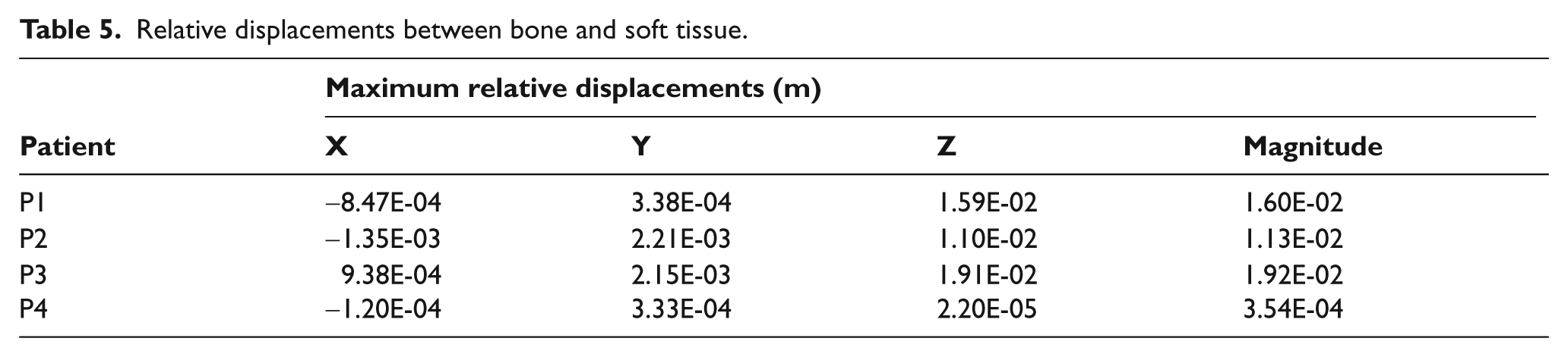
Maximum relative displacements between soft tissue and bone can be seen in Table 5. Most of the relative displacement occurs along the vertical direction as was expected for all patients except P4, who shows little relative displacement which is consequent with the small changes in its stress-strain state. For the others patients the magnitude of this displacements ranges from 1.13 cm to 1.92 cm.
Relative displacements between bone and soft tissue.
Discussion
Changes in contact definition between bone and soft tissues from tied to friction, not only modify the magnitude of the stresses and strains, but also generate changes over the stress-strain distribution patterns.
For a below the knee amputee (BK), Portnoy et al. 24 found 85% and 129% peak compressive and tensile strain respectively, while in this study the peak principal logarithmic strain values are 110% for P4 and 82.3% for P2 in compressive and tensile strain respectively. The differences can be associated with the patient specific models since the models developed by Portnoy et al. 24 were for BK amputees, while the models developed in this study were for above the knee amputees, also the constitutive equations used are different; Portnoy et al. 24 used viscoelastic, while linear elastic behaviour was used here.
Comparing the strains over the four patients involved in this study, it is possible to identify that there is a significant arise in the peak strain values, not only in compressive, but also in tensile strain when the friction condition between bone and soft tissue was considered, and this difference demonstrates the need of a patient specific model for stress-strain state determination.
When examining the stress-strain pattern distribution, there is clearly a change in the location of the maximum stresses and strains, which in the models under the tied condition (Figures 2a, 2c, 2e and 2g) are grouped mainly in the proximal zone of the soft tissues (bone-soft tissue interface), while in the models with friction formulation (Figures 2b, 2d, 2f and 2h) the maximum stresses and strains were grouped in the distal zone. These changes in magnitude and in location of the stresses and strains are due to changes in the transmission way of the vertical force.
In the models with tied formulation between bone and soft tissues, the forces are transmitted from the soft tissues to the bone through all interfaces in contact. This creates a relative uniform distribution of the stresses and strains around the bone, except in the proximal zone where the stresses and strains arise, because the edge of the soft tissue propitiates a stress concentration. Therefore the distal zone of the bone-soft tissue interface under tied formulation is not as critical as in the in the models with friction boundary condition, where the vertical forces are supported by the distal area of the bone-soft tissue interface and by the friction forces in the contact surfaces.
The decrease in the mean stresses (Figure 3b) when the formulation of the contact changes from tied to friction is due to the restriction imposed by the tied formulation of the relative displacements in all of the nodes in the bone-soft tissues, this restriction makes the load transfer occur in the entire surface of the bone-soft tissue interface and therefore submits under stress a large quantity of elements. In cases where friction formulation is used, the relative displacements of the nodes involved in the bone-soft tissue interface are allowed, and therefore the stresses are grouped in smaller areas involving a smaller quantity of elements.
Conclusions
The obtained results prove that the variation in the formulation of the contact interaction, between bone and soft tissue have a significant impact in the stresses and strains that are generated in the soft tissue, not only by magnitude but also by its distribution patterns. Therefore, this interaction should be taken into consideration when a FEM is used to evaluate or predict pathologies and injuries in transfemoral amputees.
The small quantity of patients do not allow a generic quantification of the change in magnitude and distribution of these stresses and strains when the contact formulation between bone and soft tissue changes, yet, some tendencies were found. In a study containing a higher number of patients these tendencies can be established, if they are generalized.
The relative displacement between bone and soft tissue is not only dominated by the friction coefficient, there is no data about the influence of the fasciae in this interaction, and other factors as the insertion points of the muscle in the bone or the way the remaining muscle is folded in the amputation process can modify the magnitude of this displacement, that is why an experimental measurement of the relative displacements between bone and soft tissue and the pressures in the contact interface is the next step in order to provide a deeper insight in the subject.
Due to the simplifications used in the formulation of the model such as: the materials and the boundary conditions, these results may not be a precise representation of the in vivo phenomenon; however, the consistency of the stress and strain changes between the presented models and the similar order of magnitude of the strains found within those reviewed in several references (Portnoy et al., 24 Lacroix and Ramírez Patiño 26 ) validates the results. The complete validation of the results requires the development of in vivo measurement technics, because there is no experimental data of the stresses, pressures or slips in the interface bone-soft tissue.
The method used in this study allows repeatability and it can be used to conduct a more ambitious research encompassing a greater quantity of patients in order to assess with greater accuracy the influence of the friction between bone and soft tissue in the performance of biomechanical models.
The use of friction between bone and soft tissue as a boundary condition is an important step in the formulation of more realistic numerical models of biomechanical systems.
Footnotes
Acknowledgements
The authors want to express their gratitude for the collaboration and involvement of The Neurologic Institute of Antioquia and Orthopraxis.
Funding
Partial funds were provided by National University of Colombia, research calling 2009, mode 2, codes 20201008161 and 20201008165.
Conflict of interest
The authors declares that there is no conflict of interest.