
Abstract
Background: A non-articulated plantarflexion resist ankle foot orthosis (AFO), commonly known as a posterior leaf spring AFO, is indicated for patients with motor impairment to the dorsiflexors. The AFO is often custom molded to a patient's lower limb anatomy and fabricated from polypropylene. There are no established guidelines for fabricating this type of AFO with predetermined stiffness of the ankle region for normal walking speeds. Therefore an AFO may not meet the biomechanical needs of the patient.
Objectives: Quantify the biomechanical ankle stiffness requirement for an individual with complete dorsiflexor impairment and develop a method for fabricating an AFO with ankle stiffness to meet that requirement.
Study Design: Experimental, bench research.
Methods: The literature on sagittal biomechanics of non-pathological adults was reviewed to derive the stiffness of the ankle during loading response. Computer models of 144 AFOs were created with geometric variations to account for differences in human anthropometrics. Computer-based finite element analysis was employed to determine the stiffness and safety factor of the models.
Results: Stiffness of the AFOs ranged from 0.04 to 1.8 Nm/deg. This ample range is expected to account for the stiffness required for most adults with complete dorsiflexor impairment. At 5° deflection the factor of safety (ratio of strength to stress) ranged from 2.8 to 9.1. A computer program was generated that computes AFO stiffness from user-input variables of AFO geometry. The stiffness is compared to a theoretically appropriate stiffness based on the patient mass. The geometric variables can be modified until there is a close match, resulting in AFO design specification that is appropriate for the patient.
Conclusion: Through validation on human subjects, this method may benefit patient outcomes in clinical practice by avoiding the current uncertainty surrounding AFO performance and reducing the labor and time involved in rectifying a custom AFO post-fabrication.
This method provides an avenue for improving patient outcomes by avoiding the current uncertainty surrounding non-articulated plantarflexion resist ankle foot orthosis performance. The ability to quantify the biomechanical ankle stiffness requirement for an individual with complete dorsiflexor impairment provides insight into how other AFO types should be designed as well.
Background
A non-articulated dorsiflexion assist ankle foot orthosis (AFO) is indicated for patients with flaccid equinus (foot drop) secondary to motor impairment to the ankle dorsiflexors. This AFO is often custom-molded to a patient’s lower limb anatomy and composed of a thermoplastic material such as polypropylene. The region posterior to the malleoli typically displays a narrow profile that transitions into the footplate distally and the calf band proximally. The flexibility of this region allows limited motion at the ankle joint. When weight is applied to the AFO footplate, the stiffness of the ankle region and its tendency to return to its thermoformed shape generates a resistance to plantarflexion of the ankle. 1 The AFO serves to maintain the forefoot clear of the ground during swing and to simulate eccentric activity of the dorsiflexors during loading response. From mid to terminal stance the AFO permits ankle dorsiflexion with limited resistance. 2,3 The ankle stiffness of the dorsiflexion assist AFO is dependent upon several factors: material properties, plastic thickness, cross-sectional shape of the flexible region and configuration of the trimlines. 3,4
There are no established methods for custom fabricating this type of AFO with predetermined ankle stiffness. An orthotic practitioner relies on trial and error due to an inability to anticipate the stress distribution in the orthosis. 5 The stiffness is not known in advance of fabrication and is typically not measured afterwards. Because many orthoses are over- or under-engineered, they may not meet the biomechanical needs of the patient. There is the potential for the AFO to have negative effects on knee biomechanics. Excessively stiff dorsiflexion assist AFOs behave more like solid ankle AFOs by delaying loading response. This subjects the user to an increased knee flexion moment that may threaten stance stability if the patient lacks inadequate knee or hip extensor strength. 6,7,8 Lehmann concluded that there is a positive correlation between the amount of plantarflexion resist for swing phase and the amount of knee instability induced after heelstrike. 6 A study on non-pathological subjects demonstrated that a solid ankle AFO may require 20% more activity of the quadriceps than an appropriate dorsiflexion assist AFO. 9
Studies suggest that the AFO should provide a level of plantarflexion resist that simulates eccentric contraction of the dorsiflexors, thereby allowing a limited amount of loading response plantarflexion to occur. 7,8,10,11 For this reason a dorsiflexion assist AFO is contraindicated for individuals presenting with plantarflexor spasticity that would overpower the stiffness control. 12 A study by Geboers et al. involving immobilization of the ankle and its effect on dorsiflexor strength concluded that people using an AFO after neurological damage risk further strength loss due to disuse. 13 A study by Hesse et al. concluded that reduced dorsiflexor activity may lead to disuse atrophy and long-term dependence on the orthosis. 14 Thus an AFO that provides excessive ankle stiffness could delay rehabilitation if the patient were expected to recover from the neurological damage. Patients should be fitted with an AFO having the minimal ankle stiffness required to promote a functional gait pattern. However, if the AFO stiffness is insufficient there will be inadequate biomechanical control of ankle motion during gait. Loading response may be too brief, which may create an excessive knee extension moment. Considering these consequences, it would be beneficial if orthotists had the ability to design a custom thermoplastic dorsiflexion assist AFO with predetermined stiffness that meets the needs of a patient. The purpose of this research was to develop a method for accomplishing this.
Materials and methods
In order to arrive at a method for achieving AFO ankle stiffness, it was first necessary to understand the biomechanical control necessary to restore function in an individual with complete dorsiflexor impairment. Thus the literature on the sagittal biomechanics of the non-pathological ankle was reviewed. Research has shown that the eccentric activity of the dorsiflexors during loading response can be modelled as a torsional spring with a linear spring rate. 15 Published gait data from non-pathological subjects was used to determine the AFO spring stiffness. Winter reported instantaneous values of internal ankle joint moment normalized for body weight throughout the walking gait cycle, with cadences ranging from approximately 85 to 125 steps per minute. 16 It was possible to calculate the average stiffness of the ankle over the first 6% of the gait cycle that corresponds to the controlled plantarflexion beginning at heel strike (Appendix A1). This stiffness was in units of torque per angular change per body mass (Nm/deg/kg). There was a positive correlation between walking speed and calculated ankle joint stiffness. Palmer provided stiffness data for 10 non-pathological subjects, which was converted into these units (Appendix A2). 15 Palmer’s mean ankle joint stiffness values for slow, normal and fast walking speeds of approximately 0.9 to 1.8 metres per second showed no such correlation, yet the overall mean was of similar magnitude to Winter’s normal-speed walkers.
In order to create fabrication guidelines that consider differences in human anthropometrics and biomechanical requirements, a wide range of AFO geometries needed to be tested. However, the labor and materials involved in fabricating and experimentally testing many thermoplastic AFOs would have been cost-prohibitive. Therefore a more efficient method involving computer-based finite element modelling (FEM) was employed. FEM reduces a physical structure to smaller substructures known as finite elements. These substructures and their interrelationships are used to determine the magnitude and distribution of stress and deflection under loading conditions. Although FEM can be very accurate, it is recognized that the multiple AFO geometric variables measured in this study are all sources for error. Therefore it was necessary to first evaluate the accuracy of FEM when used for the purposes of this study. A pilot study compared 10 polypropylene dorsiflexion assist computer models against real AFOs. 17 The real AFOs were fabricated to have geometry that closely matched their respective computer models at the level of the ankle where the majority of stress and strain was expected to occur. For each AFO, theoretical FEM and empirical testing resulted in less than 10% difference in stiffness.
One variable affecting the stiffness of a dorsiflexion assist AFO is the
cross-sectional shape of the posterior extension. This shape is based on patient
anatomy. A transverse sectional view of the anatomy at the level of the ankle
demonstrates an irregular posterior contour (Figure 1). This contour is unique for every
individual. Quantifying the expected stiffness of an AFO that matches the posterior
anatomy would require prior acquisition of a 3D patient model and the use of
analytical software. This technology is available but has not been universally
applied to orthotic clinical practice. To be useful and promote acceptance, a new
fabrication technique should be based upon current practice. Today this generally
involves generating a positive model of the patient’s anatomy via a
negative impression. The model is then rectified to ensure an AFO fabricated from
thermoformed plastic will fit and function correctly. In order to base new
guidelines on this practice and to avoid the issue of complex anatomy, it was
decided that the region where the AFO bends should be of a generic shape with
pre-determined dimensions (Figures
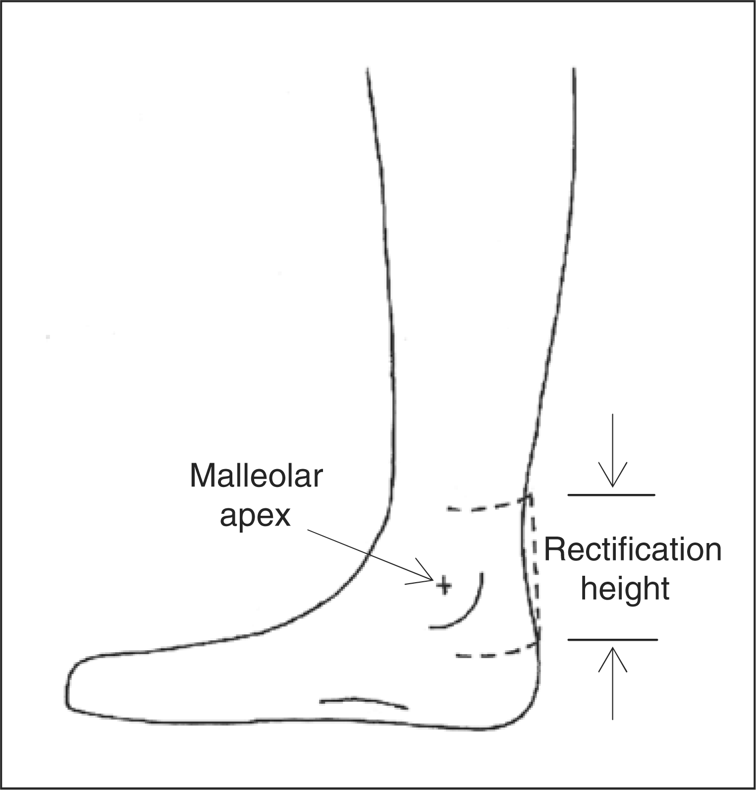
1 and 2). This
was done by rectifying the posterior positive model to create a constant radius in
the transverse plane that extends over a vertical range, beginning proximal to and
ending distal to the malleolar apices. The other aspects of the AFO would remain
custom molded to the anatomy to ensure an appropriate fit. Transverse ankle cross section with irregular posterior anatomy
(——) and rectification radius
(- - -). Vertical range of rectification (- - -) to create
the posterior extension.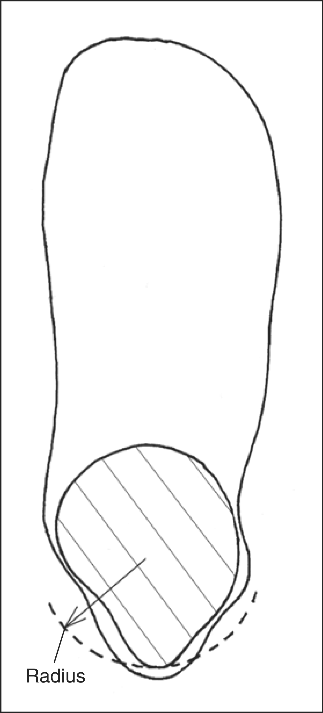
Computer models of 144 AFOs were created. Each AFO model had a unique flexural zone
geometry to account for variations in human anatomy and to provide varying levels of
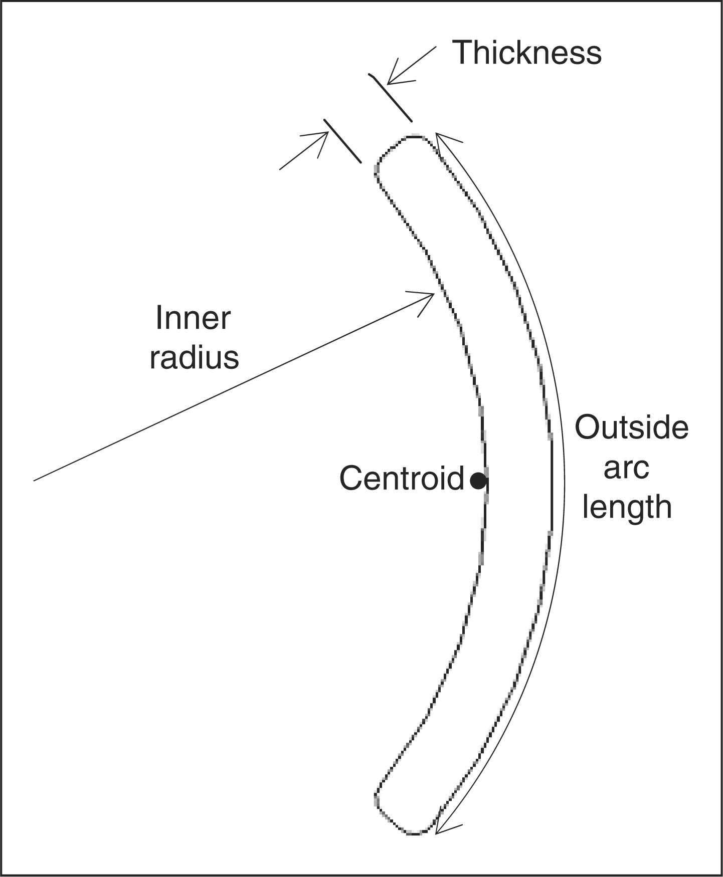
stiffness. Geometric measurements that defined the flexural zone were: transverse
plane inner radius, outside arc length, plastic thickness, sagittal zone height, and
the radii of the transition from the flexural zone to the rest of the AFO shape
(Figures 3 and 4). The inner radius was equal
to the rectification radius and the rectification height was intended to be ample
enough to span both the height of the zone and its transitional radii. Zone radius
and height were based upon anthropometric values for bimalleolar width and malleolar
height among adult males and females.
18,19
All measurements that
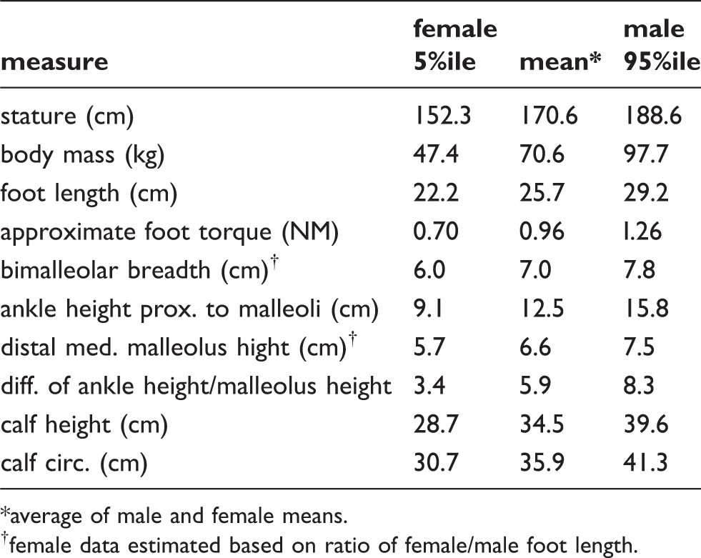
influenced the models are listed in Table 1. For the 5th percentile, mean and
95th percentile, bimalleolar diameters approximately matching transverse radii of
30.2, 36.5 and 44.5 mm, respectively, were used. These corresponded to
the inner radii of Schedule 40 PVC pipe couplers with nominal dimensions of 2, 2.5
and 3 in. For each percentile and mean group, three different zone
heights were used to ensure that the zone height and transitional radii were ample
enough to avoid plastic impingement on the region of malleolar prominences as
predicted by the anthropometric values for ankle height and distal malleolus height.
The mean foot length, calf height and calf circumference values were used to define
the remainder of the AFO model shape. Stature and body mass did not influence the
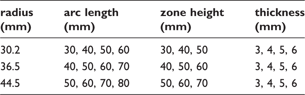
models but are included for reference. For each of the small, medium and large inner
radii, 48 models were created with combinations of four plastic thicknesses, four
arc lengths and three zone heights. A summary of the combinations are listed in
Table 2. Sagittal flexural zone geometry. Transverse flexural zone geometry. Anthropometric data. average of male and female means. female data estimated based on ratio of female/male foot length. Flexural zone geometry combinations.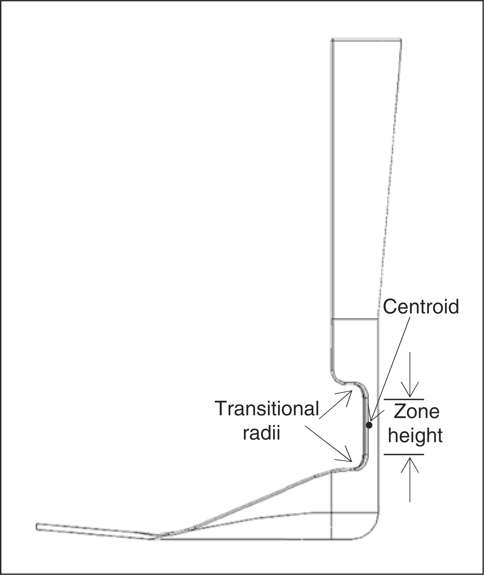
Computer-assisted design software (SolidWorks®, Solidworks Corporation,
Concord, MA) was used to create solid models (Figure 5). Regardless of flexural zone
geometry, a 12.5 mm transitional radius was used to blend the proximal
and distal flexural zones into the remainder of the structure (Figure 3). A finite element analysis tool
(CosmosWorks®, Solidworks Corporation, Concord, MA) was used to
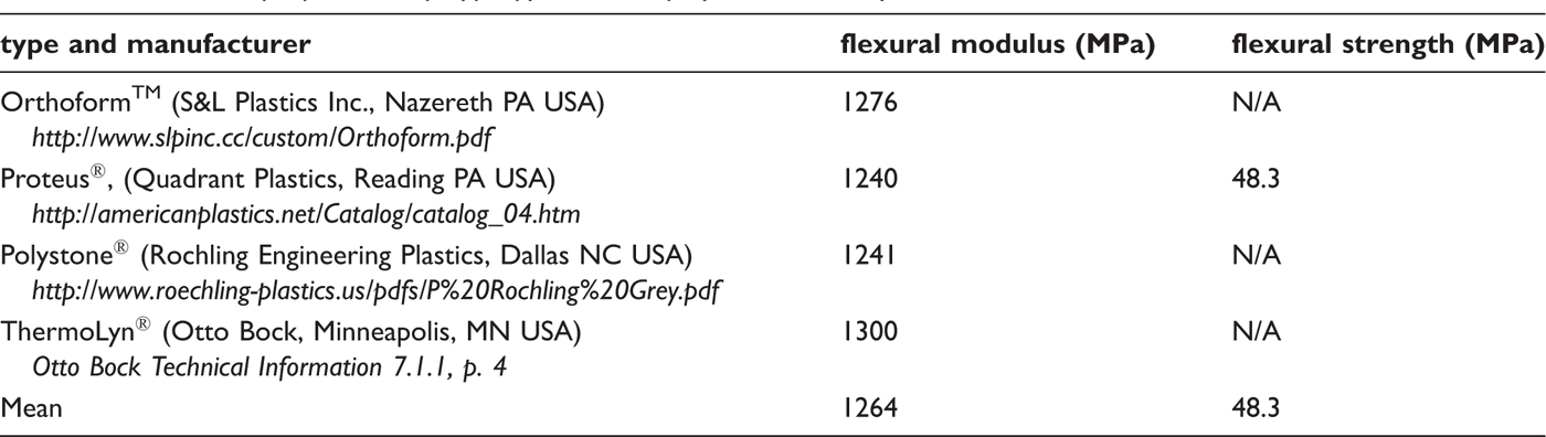
determine AFO stiffness and peak stress. The mechanical properties of polypropylene
from several orthotic and prosthetic plastic manufacturers were averaged and entered
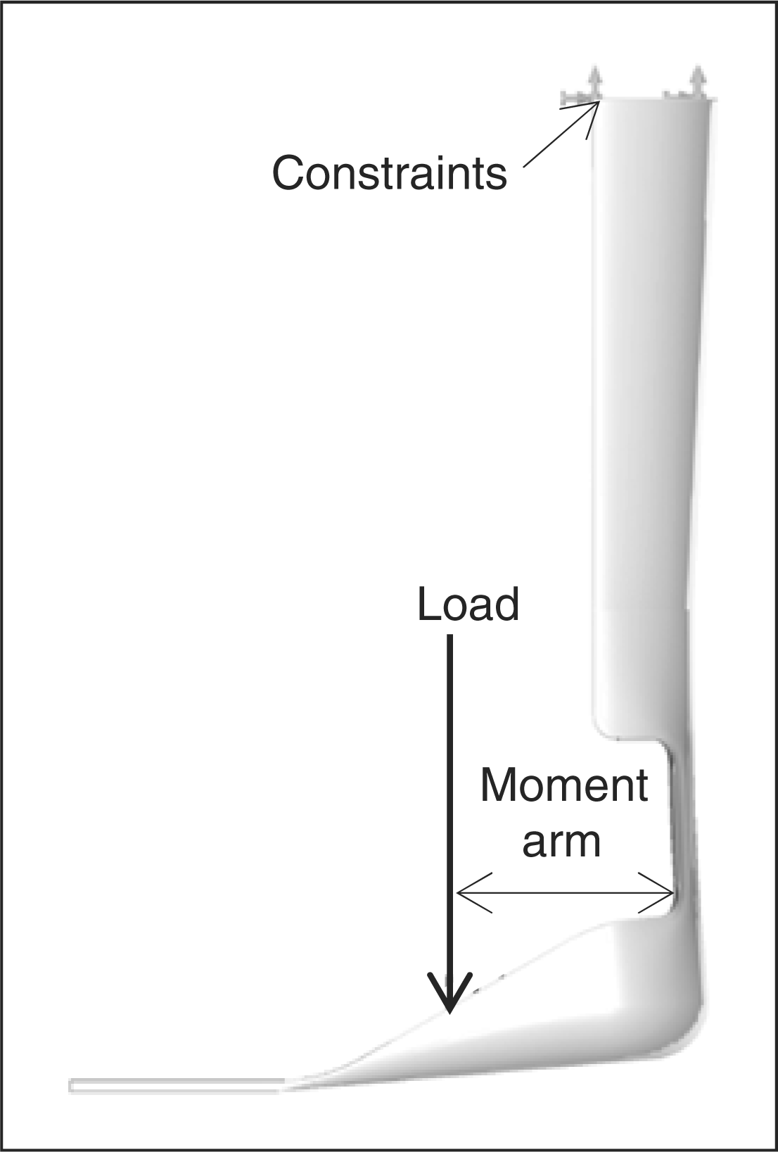
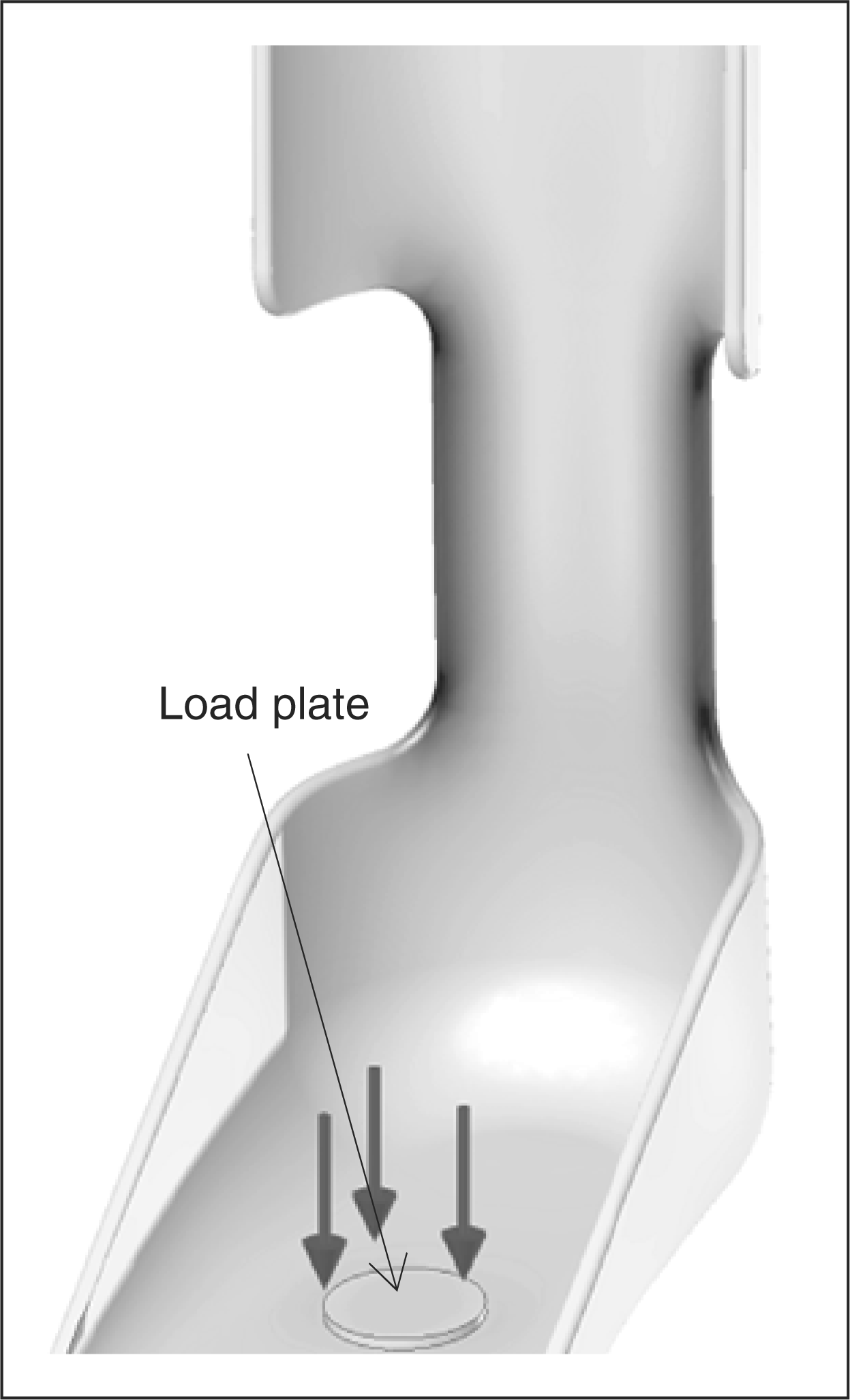
into the software as a linear elastic material (Table 3). Each model was restrained at the
proximal shank and a normal force was applied to the footplate to represent the
resultant of the distributed load from the foot. The load required to elicit
5° deflection in the direction of plantarflexion was determined,
utilizing an iterative technique that accounted for geometric changes occurring
during a large displacement (Figure
6).
20
This amount of deflection approximates the amount of ankle plantarflexion
that occurs during loading response at a non-pathological self-selected walking
cadence. The required force and peak von Mises stress were recorded for each model.
The moment arm was defined as the distance between the applied force and the
centroid (centre of bending) in the transverse plane. The moment was calculated and
converted to stiffness units of moment per angle (Nm/deg). From the peak von Mises
stress, the factor of safety (ratio of strength to peak stress) at 5°
plantarflexion was calculated. Computer-generated AFO model. AFO deflection post-analysis. Mechanical properties of polypropylene homopolymer commonly used in
orthotics. Poisson's ratio of 0.35 was used.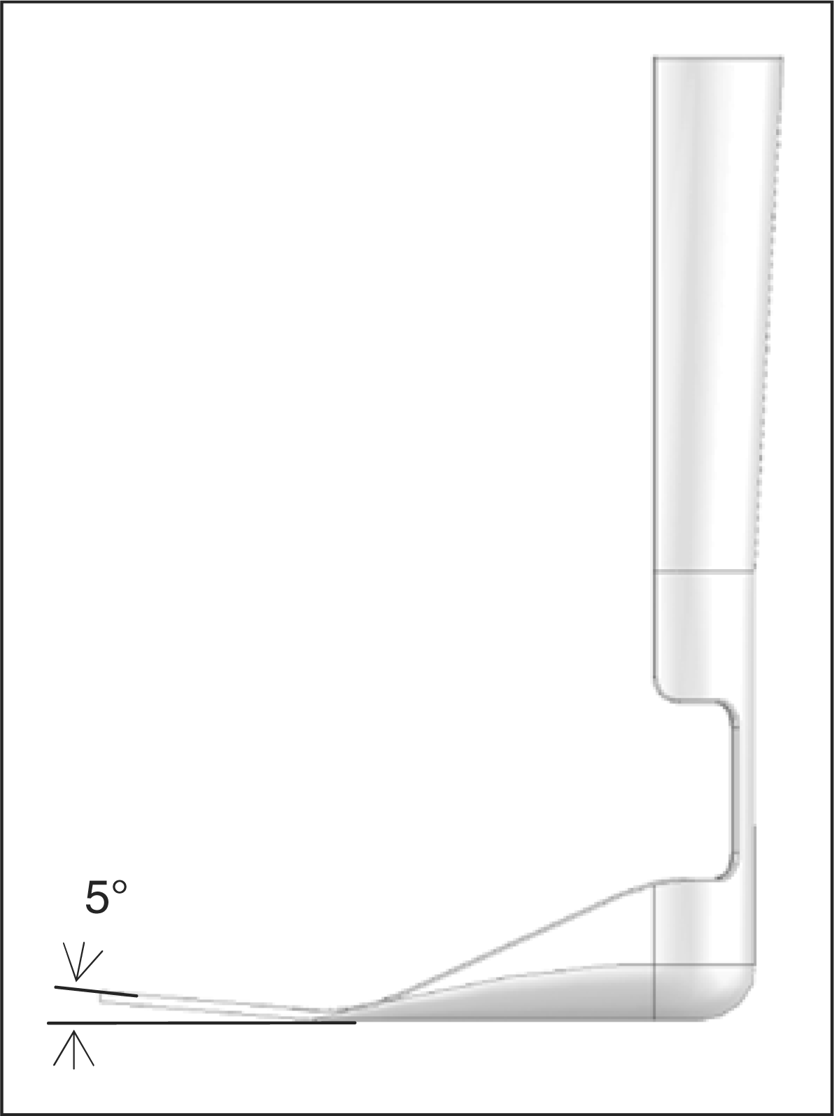
Results
Stiffness of the AFOs ranged from 0.04 to 1.8 Nm/deg. The results using
the iterative loading technique were on average 11.2% greater than if
geometric changes during deflection had not been considered. At 5°
deflection the factor of safety (ratio of strength to stress) ranged from 2.8 to
9.1. For each zone height and plastic thickness combination (12 per radius size),
stiffness was plotted against the four arc lengths (Figure 7). Using second order polynomial
trendlines, it was possible to input arc length and determine the stiffness with a
high level of accuracy in relation to the data points (coefficient of determination,
R2 > 0.99). The same was true for
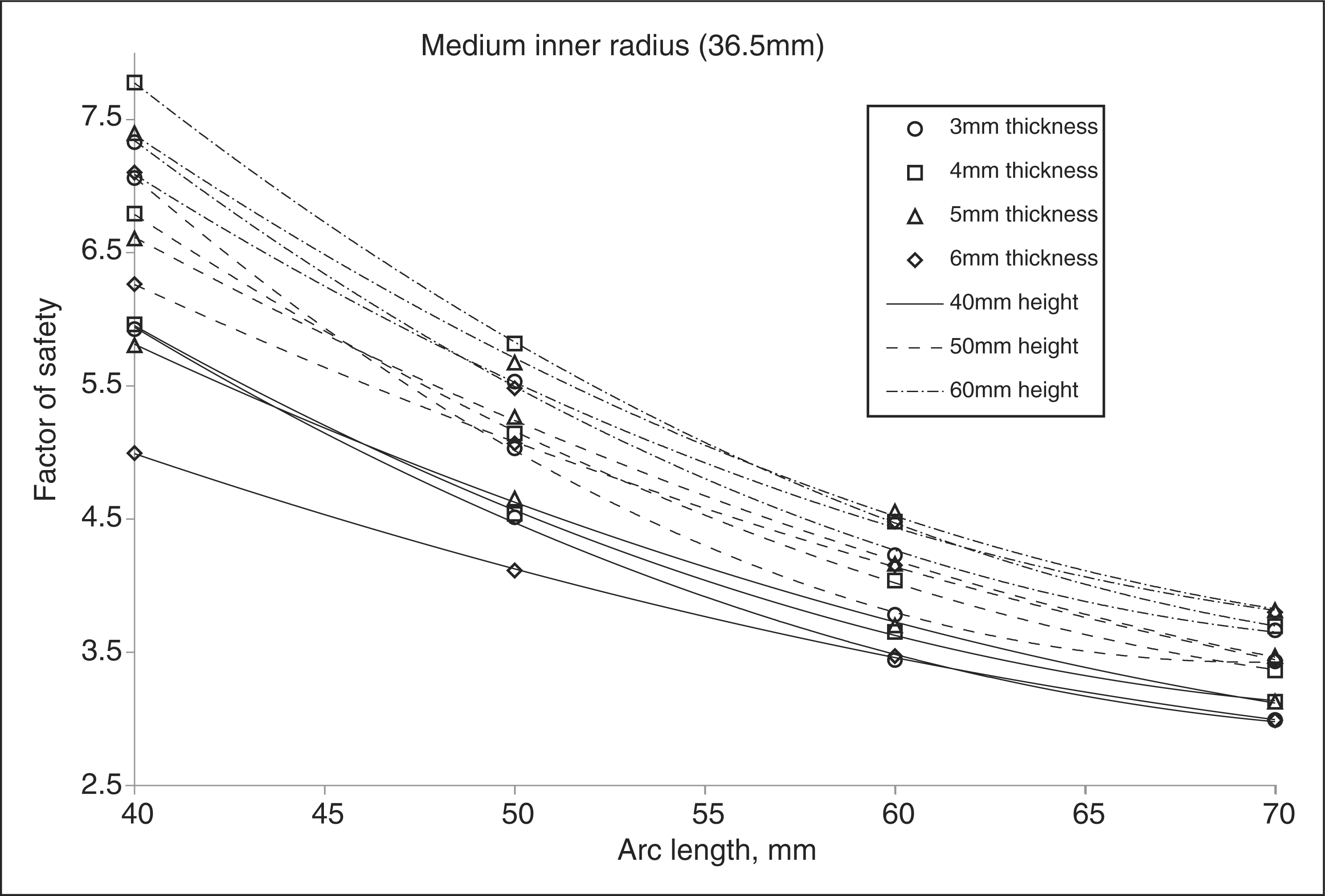
factor of safety versus arc length (Figure 8). The maximum differences between the stiffness data points and
the trendlines were 3.53%, 1.82% and 0.76% for
AFOs having small, medium and large transverse radii, respectively. The maximum
differences for factor of safety were 5.08%, 1.31% and
1.83%. The medium AFO trendline in Figure 7 demonstrates that a large arc length
and a small zone height result in the greatest stiffness. However, from Figure 8 it is seen that they
also result in the lowest factor of safety. A large stiffness can be achieved
without sacrificing flexural strength by using a thicker plastic, thereby making it
possible to use a smaller arc length and/or larger zone height. From the results of
finite element analysis, peak stresses always occurred along the inner edges of the
flexural zone, particularly at the transitional radii (Figure 9). If an AFO were to become
excessively stressed, its failure would begin in one of these locations. AFO stiffness vs. arc length for medium inner radius. AFO factor of safety vs. arc length for medium inner radius. Inner aspect of AFO with darkened regions representing areas of greatest
stress under load.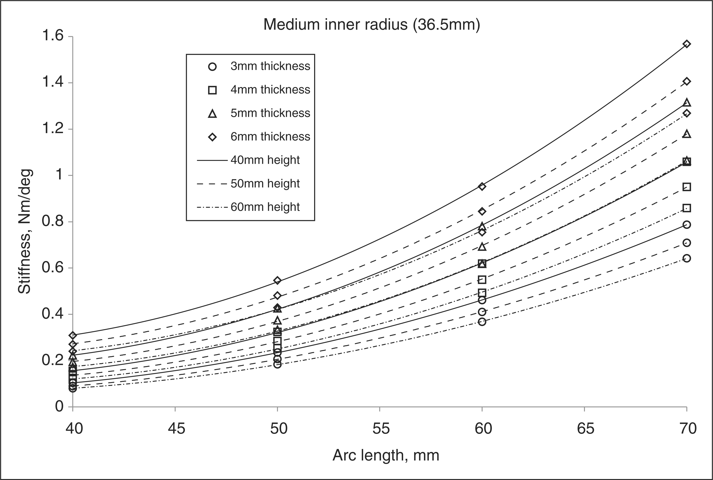
Discussion
For each size of cross-sectional radius listed in Table 2, a calculation tool was created in Excel 2003 (Microsoft Corporation, Redmond WA) spreadsheet format. The calculation tool programming was based upon the data point trendline equations exemplified in Figures 7 and 8. Increased resolution of thickness was possible through linear interpolation between equations representing consecutive whole number thickness values listed in Table 2. The calculation tool determines the stiffness of an AFO based on flexural zone geometry and compares the stiffness to that recommended for a person with complete dorsiflexor impairment (sample in Appendix B). This tool serves as a guideline for an orthotist to fabricate an AFO.
A physiological stiffness factor of 0.01 Nm/deg/kg for a non-pathological person was used to represent the lower end of the range of values derived from the literature. 15,16 This is a value normalized for body mass and when multiplied by a subject’s mass results in expected non-pathological ankle stiffness during loading response. It was chosen based on an expectation that the average patient treated with an AFO will ambulate within the slow to natural cadence/speed range of the non-pathological subjects studied by Palmer and Winter (Appendix A). The average stiffness factor of the slow and normal walking speeds from both Palmer’s and Winter’s studies was 0.0115 Nm/deg/kg. A low-magnitude factor was further presumed to be appropriate because a dorsiflexion assist AFO bends on an axis posterior to the anatomical ankle axis. 21 The reduced heel lever results in less plantarflexion moment that the ground reaction force can induce on the AFO structure as compared to the anatomical heel lever of a non-pathological subject. Additionally, any intrinsic resistance to plantarflexion remaining in the impaired ankle will further reduce the stiffness requirements of the AFO design.
The stiffness factor used in this study only accounts for patient body mass while other variables such as walking speed and limb length may also influence ankle stiffness. The stiffness of a passive dorsiflexion assist AFO cannot adapt to changing demands; therefore an ankle stiffness appropriate for a ‘slow’ to ‘normal’ speed was the basis for analysis. Further gait studies are necessary to determine the optimal physiological stiffness factor. This could be accomplished by repeating the research of Winter and Palmer with a larger sample size of non-pathological subjects and accounting for stature or limb length. It would be ideal to test the subjects at walking speeds that match those of the self-selected speeds for users of dorsiflexion assist AFOs. Presently, a practitioner has the ability to fabricate an AFO with excess initial stiffness and subsequently reduce stiffness through reconfiguration of trimlines to optimize patient gait. 3
A pilot study was performed that compared stiffness of actual dorsiflexion assist AFOs with computer models of similar AFOs, resulting in less than 10% difference. 17 Being able to provide an AFO with a predetermined stiffness that is 90% accurate should be acceptable to most practitioners. It is anticipated that a similar level of error would be present in AFOs fabricated using the technique described. Empirical testing would be beneficial since the theoretical results in this study encompassed a greater number of AFOs having a broader range of geometries. Sources of error include differences in thermoformed polypropylene flexural modulus and strength as compared to manufacturer data and how well the computer models reflect a fabricated AFO shape. The maximum difference between the average polypropylene flexural modulus and individual values was 2.8%, indicating consistency between the selected manufacturers. A thermoformed AFO with transverse flexural zone radius that is larger than the positive model due to ‘spreading’ from thermoforming insufficiency will be more flexible than intended. Techniques to avoid or rectify this phenomenon are necessary.
Estimate of swing phase deflection based on anthropometric data and AFO stiffness.
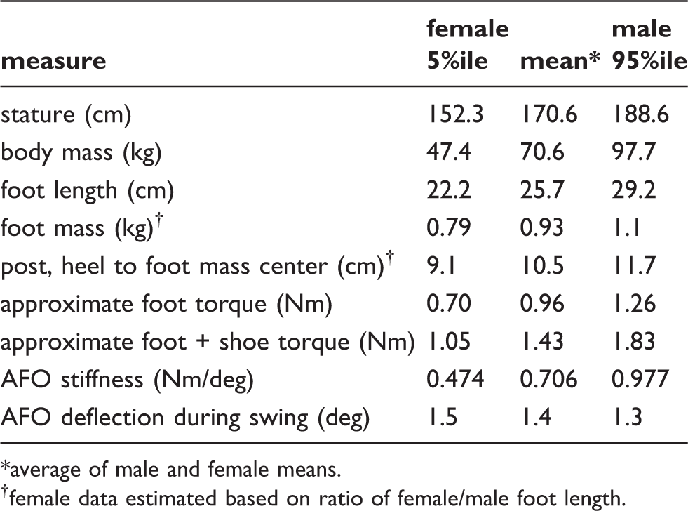
average of male and female means.
female data estimated based on ratio of female/male foot length.
A single AFO was fabricated using the instructions described in Appendix C to assess the technical challenges and additional time involved when compared to fabricating a traditional dorsiflexion assist AFO. Fabrication instructions can be accessed at http://sites.google.com/site/afostiffness/. The additional step of creating a constant radius build-up posterior to the malleoli added a few minutes to the fabrication process. More time was spent carefully delineating the flexural zone and finishing the trimlines. The fabrication process took approximately 50% more time than would have been spent on a standard dorsiflexion assist AFO and no unexpected technical challenges were encountered. As with any new task, repetition of the process reduces the time involved. Stiffness of the AFO was not quantified and was not tested on a human subject. The AFO was loaded into plantarflexion and dorsiflexion. During dorsiflexion it was visually observed that the center of bending occurred in the distal flexural zone and that diametrical strain occurred in the heel section just distal to the flexural zone. In plantarflexion the center of bending occurred closer to the mid-level of the flexural zone and no diametrical strain was visually observed. Dorsiflexion of the AFO required less force than plantarflexion. This has been reported to occur in traditional dorsiflexion assist AFO designs as well. 22 It also supports the established contraindication of a dorsiflexion assist AFO for a patient that has significant plantarflexion weakness as it provides poor control of tibial advancement during stance. 3,12,24
Conclusion
This research serves as a starting point for stiffness control of custom polypropylene dorsiflexion assist AFOs. The guidelines and calculation tools are intended for experimental use and validation through further research. If proven to be a reliable technique, orthotists would have a new method for AFO fabrication that avoids trial and error. Less time would be spent on modifications to achieve appropriate AFO performance. The practitioner would have greater confidence in the durability of an AFO. By recording the stiffness of a patient’s AFO it would be less difficult to reproduce it if it were to need replacement. The overall result would be improved patient outcomes and time savings for both patient and practitioner.
Footnotes
Acknowledgments
William J Barringer, MS, CO; Gary S Trexler, CO; Jonathan D Day, CPO – University of Oklahoma Health Sciences Center, Department of Orthopedic Surgery and Rehabilitation, Orthotics and Prosthetics Section, USA; Christopher F Hovorka, MS, CPO, FAAOP – Georgia Institute of Technology School of Applied Physiology, USA and Dr David P Miller, PhD – University of Oklahoma School of Aerospace and Mechanical Engineering, USA.
Funding
This research received no specific grant from any funding agency in the public, commercial or not-for-profit sectors.
Appendix A1. Internal ankle moment (stiffness) characteristics of non-pathological subjects
Derived from: Winter DA. 1991. The biomechanics and motor control of human gait: normal, elderly and pathological. 2nd ed. Waterloo: University of Waterloo Press. pp 121–9.
Appendix A2. Internal ankle moment (stiffness) characteristics of non-pathological subjects
Derived from: Palmer ML. 2002. Sagittal plane characterization of normal human ankle function across a range of walking gait speeds. Thesis submitted to Department of Mechanical Engineering, Massachusetts Institute of Technology, Boston, MA.
Appendix B1. Sample calculation tool results for 70 kg patient using 36.5 mm inner radius,pre-thermoforming
– Preliminary results based on expected plastic
thickness.
Appendix B2. Sample calculation tool results for 70 kg patient using 36.5 mm inner radius,post-thermoforming
– Updated results based on plastic thickness measured
post-thermoforming.
Appendix C. Fabrication instructions for a non-articulated dorsiflexion assist AFO with predetermined stiffness
A patient impression should be obtained with the ankle in 2–3° additional dorsiflexion than would be used for a solid ankle AFO. This alignment will limit the footplate from plantarflexing beyond neutral when subjected to the gravitational forces of the foot and shoe during swing. This will maintain adequate ground clearance and will pre-emptively compensate for AFO fatigue or deformation that contributes to excessive plantarflexion over time. Mark the apices and borders of the malleoli with an indelible pencil. Mark all other relevant anatomy.
This fabrication technique requires the use of a shaping tool made from a PVC
pipe coupler with diameter equal to or slightly larger than the mediolateral
distance between the malleolar apices. For adults of small, average and large
size, PVC pipe couplers of 2, 2.5 and 3 in nominal dimension provide
the necessary diameters. Each tool is created from about 1.5 in
(4 cm) × 150° of the
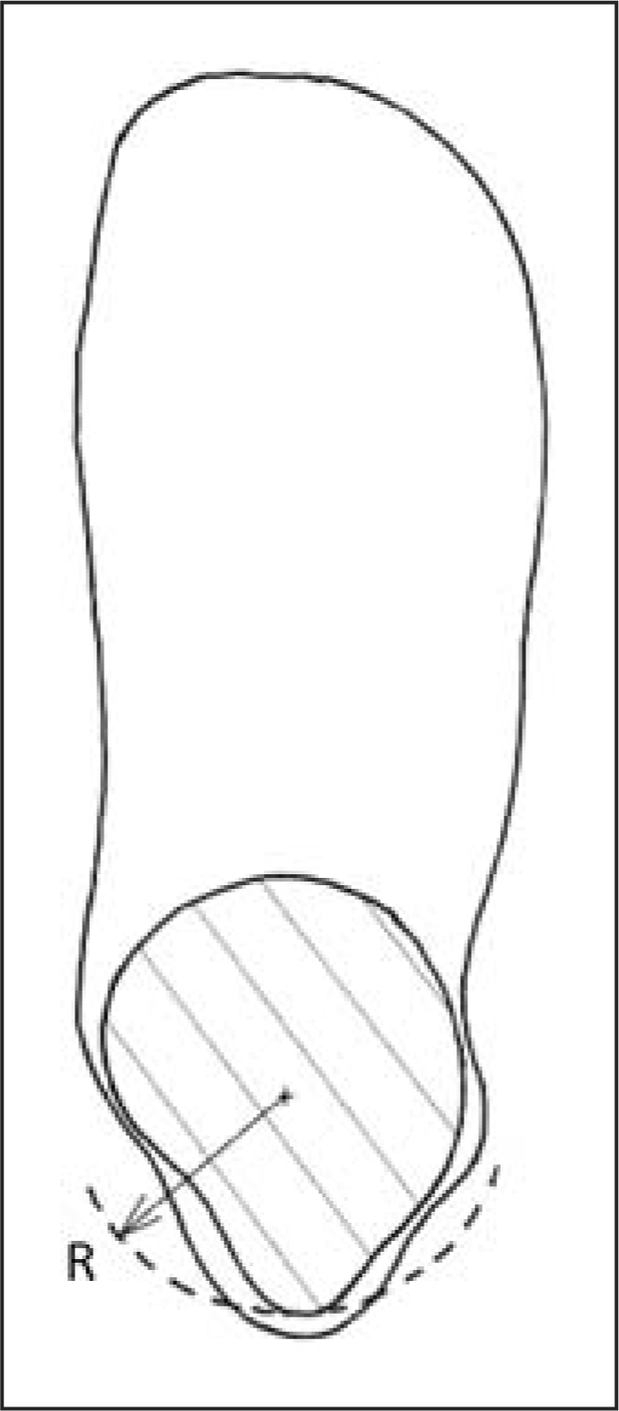
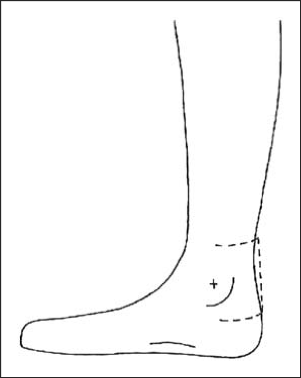
coupler with the corners and inside edges rounded (Figure C1). The shaping tool is used to
create a plaster build-up on the posterior positive model at the level of the
malleoli (Figures C2
and C3). The chosen
radius should not be excessively large as this will make it difficult to
transition the proximal and distal ends of the build-up back into the remaining
positive model. The radius should not be so small that it curves into the medial
and lateral model, which could cause plastic impingement. The build-up should
extend from the posterior calcaneus to at least 1 to 2 cm above the
proximal border of the medial malleolus. It should wrap around the ankle
approximately 180°. A build-up for the posterior calcaneus can be
provided before or after creation of the posterior radius. If provided after, it
must not encroach upon the intended flexural zone as this would affect the cross
sectional shape. Shaping tool made from PVC pipe coupler. Transverse radius (R) of rectification. Sagittal range of rectification.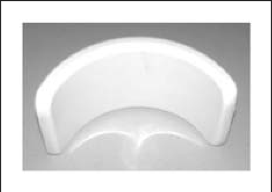
The calculation tool (http://sites.google.com/site/afostiffness/) recommends the AFO stiffness based on patient weight and helps determine an appropriate plastic thickness for thermoforming. Use the calculator corresponding to the rectification radius used. Enter patient weight in kilograms. A theoretical stiffness is given that assumes complete dorsiflexor impairment. Enter a sheet plastic thickness. Select a zone height from the available values and an arc length value within the recommended range. Alter zone height and arc length until stiffness is optimized to match that recommended for the patient’s weight. Ensure that the factor of safety is at least 3. To increase the safety factor, increase the plastic thickness value followed by a reduction in arc length and/or increase in zone height to maintain stiffness. The plastic will be measured subsequent to thermoforming to fine-tune the calculation and determine the final flexural zone trimlines.
Thermoform the AFO with the polypropylene thickness determined from the
calculation tool. Avoid stretching the plastic around the heel and posterior
positive model as this could affect the distal flexural zone thickness. Plastic
spreading in the flexural zone should be avoided, as any change to the geometry
will affect stiffness. Otherwise the shape must be corrected later to match the
model. Once the plastic has cooled, draw a vertical line on the posterior
plastic to bisect the flexural zone in the coronal plane. Trace a horizontal
line distal to malleolar prominences yet remaining within the distal end-range
of the posterior radius. Trace another horizontal line at a proximal distance
equal to one of the zone height values given by the calculation tool and
sufficient to clear any malleolar prominence. Finally, trace vertical lines to
each side of the bisection line at a surface distance equal to half of the
maximum arc length specified in the calculation tool (Figure C4). The final arc
length will be determined later. Posterior AFO with a selected zone height and maximum arc length
defined.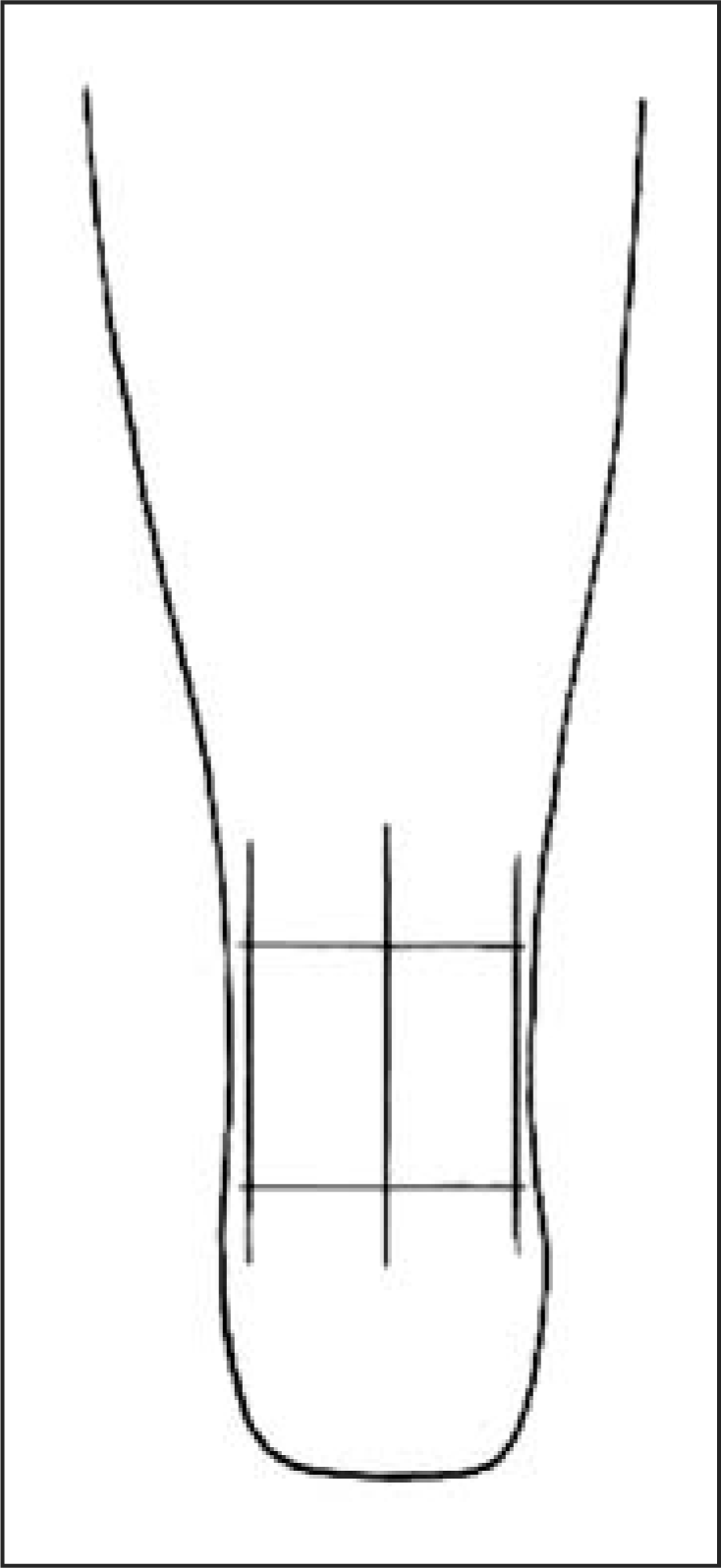
Trim the plastic at least 25 mm anterior to the flexural zone, leaving enough material to transition anteriorly from the proximal and distal ends of the flexural zone into the rest of the AFO shape. At the proximal and distal flexural zone, measure the plastic thickness on the medial and lateral sides with a micrometer or calliper. Enter the average thickness to the nearest 10th of a millimeter into the calculator and modify the zone height and arc length until the appropriate stiffness is achieved.
Define the final zone height with horizontal lines and the arc length with
vertical lines. Trace a quarter circle transition with 12.5 mm
radius between the horizontal and vertical lines using a pencil or other
fine-tipped writing instrument and a template such as quarter US dollar (Figure C5). On each side
of the AFO extend the trimline anteroproximally to create a transition into the
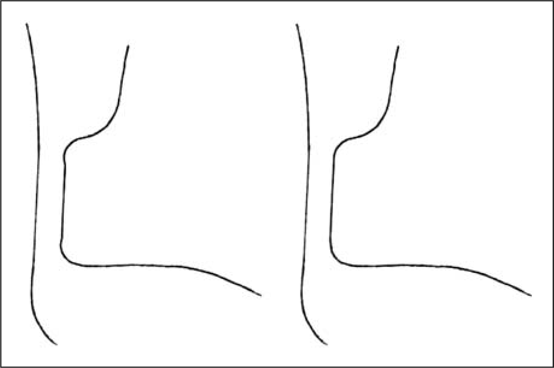
calf band shape. Ensure that the arc length at the mid-level of the zone is not
greater than the arc length at the level of the transitional radii, or else
stresses at the transitions will be amplified and lead to premature failure of
the AFO (Figure C6).
Carefully finish and round the trimlines, ensuring that they are smooth and free
of surface imperfections that could lead to premature AFO failure. AFO trimlines refined with the corrected arc length (A) after
initially defining the maximum arc length (B). Incorrect flexural zone trimlines (left) and correct trimlines
(right).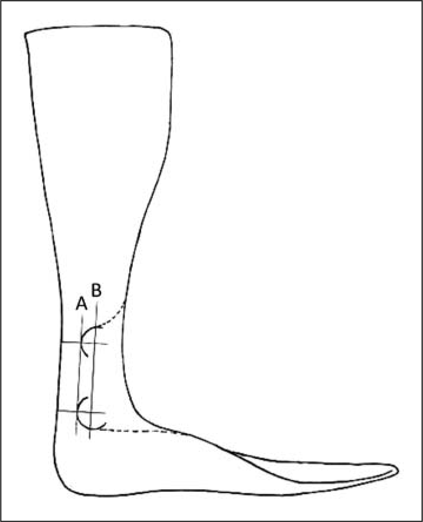
Fit the AFO to the patient. When modifying the footplate or calf section to optimize the fit, avoid the flexural zone. Any modification to the flexural zone shape will affect the stiffness! Observe the patient ambulating at a self-selected normal speed. If loading response plantarflexion is inhibited or if instability of the knee is induced, the arc length of the flexural zone can be reduced to improve loading response and enhance knee stability. If abrupt, uncontrolled plantarflexion occurs the stiffness is insufficient. Once the AFO optimally affects the gait pattern through clinical observation, the final zone dimensions should be entered into the calculator to determine the final AFO stiffness. This value can be included in the patient record so that an AFO of equivalent stiffness can be reproduced in the future.