
Abstract
Objective
The aim of this study was to evaluate, using the finite element method (FEM), the stresses generated on various parts of the mini-screw and on the bone resulting from the insertion of mini-screws of varying lengths and under different forces.
Materials and Methods
Three-dimensional models of mini-screws (1.6 × 6, 8, and 10 mm) and bone (mandible cortical bone thickness of 2 mm) were constructed and simulated using FEM. The mini-screws were inserted using force loads of 10 and 20 Ncm, and stress evaluation was carried out on screws and bone. The stress evaluation was also performed across different levels of insertion (at the point of insertion, half-insertion, and full insertion).
Results
A direct correlation between the force applied and the stresses on the body of the screws was observed. There was an inverse relationship between the length of the mini-screw and the resulting stress on the bone with the highest stress of 14.58 Mpa with 6 mm long and the minimum stress of 3.81 Mpa with longer mini-screws. On application of different force magnitudes, the stress levels increased linearly with a change in the length. The highest stresses on the bone were observed only when the screw was fully inserted in the bone.
Conclusion
When mini-screws of different lengths were inserted using different magnitudes of forces, the stress levels increased linearly on the bone. A combination of longer mini-screw and lesser force magnitude used during insertion produced less stress on the bone.
Introduction
The success rates of mini-screws have been reported to range from 80% to 89%.1, 2 Despite the documented benefits of using mini-screws for various types of tooth movement, one of the principal problems faced by orthodontists is loosening of mini-screws.3, 4 Several studies have been conducted on the clinical behavior of mini-screws and have concluded that a variety of factors such as type of mini-screws, dimensions, angle of insertion, insertion torque and force, placement site, and even proximity to roots are responsible for the success or failure of mini-screws.5–10
Although the success of mini-screws can be attributed to multiple factors, primary stability has been shown to be of utmost importance. Primary stability of mini-screws is observed in bone remodeling, and it can be described as a favorable tissue response from the hard tissues. The positive tissue response depends on the stress–strain response elicited during the initial placement of the mini-screws. 7 To predict the outcome of mini-screw placement, it is essential to measure the stresses generated on the mini-screws and hard tissues during the insertion of mini-screws. However, such stress measurements during the insertion procedures cannot be performed intra-orally. Finite element analysis (FEA) is one of the established methods to visualize and measure the biomechanical stresses generated during the placement of the mini-screws.5 Previously published literature has shown a positive correlation between the biomechanical characteristics of mini-screws and their in vivo performance.5, 11
The Temporary Anchorage Devices (TADs) placement torque (PT) is defined as the quantifiable measure of resistance to insertion of the anchorage device. It has been seen that the insertion torque is higher in the mandible compared to the maxilla, and there are more chances of failure of the TADs because of high torque during placement.12, 13 PT values below or above a certain threshold have been associated with up to 12 times higher risk for early failure.
Excessive force application can damage the mini-screws and the surrounding tissues, which could result in adverse effects on the patients. Hence, the current study was conducted to better understand the precise lengths and forces that are required to place orthodontic mini-screws on several sites of the mandible.
Objectives
The objectives of this study are as follows:
To compare stresses on different parts of mini-screws of different lengths when they are inserted into the mandibular bone.
To evaluate and compare stresses on the bone when mini-screws of different lengths are inserted with different force magnitudes.
Materials and Methods
Mini-screws (Dentaurum, Langhorne, PA, USA) of dimensions 1.6 × 6, 1.6 × 8, and 1.6 × 10 mm were used (Figure 1). The forces required to insert the various lengths of mini-screws on different sites of the mandible were measured using a torque gauge. Using a finite element model of the mandible with a cortical bone thickness of 2 mm overlying trabecular bone and considering the material properties of the mini-screws, the analysis was done to find out the best length of mini-screws for a particular area of the mandible.
The Three-dimensional Construction Model of the Screw.
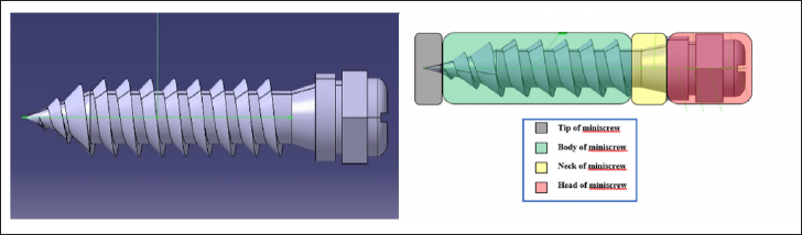
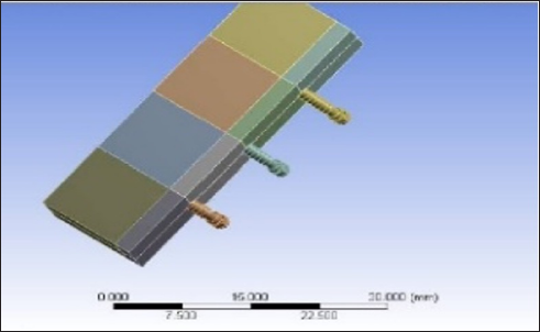
In the current study, the main areas considered for the study were the neck, the body, and the tip of the screw, as well as the corresponding areas on the alveolar bone during the insertion of the mini-screws. 3 Lengths of mini-screws were compared (6, 8, and 10 mm) when applying an insertion torque of 10 and 20 Ncm at various sites of the mandible. Further, the stresses were observed on the different parts of mini-screws and the alveolar bone to figure out the suitable length for that area of bone; hence, any additional stress or complications can be avoided. The dimensions (length, outer diameter, depth, pitch, and the lead angle) of the mini-screws were adapted from a previous study 14 (Figure 1). A three-dimensional mathematical finite element model was designed for analysis using CATIA software after applying the measurements from the previous step. After acquiring the images or dimensions, the following step was modeling the screws and the bone. The mandibular cortical and trabecular bone blocks were designed using MIMICS software (Materialise NV, Leuven, Belgium) using three-dimensional mathematical models (Figure 2). The material properties used in this study were adapted from a previous finite element study 5 done on elasticity and Poisson’s ratio of the cortical and trabecular bone of the mandible. Further, the virtual geometric models were divided into several finite elements. ANSYS software (Versetia Technologies, ANSYS workbench 12, Canonsburg, PA, USA) was used to create the FEA. After the preparation of the finite element models, mechanical properties were applied to the bone models along with the mini-screws (Figure 3).
Simulated Screws in the Bone Block Model.
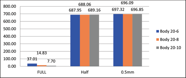
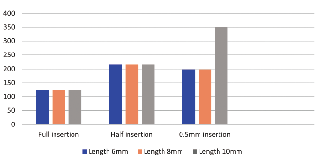
Bar Graph Showing Stress Analysis on the Body of Different Lengths of Screws at Different Levels of Insertion with Force Magnitude of 20 Ncm Torque.
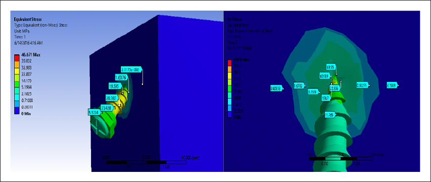
Following the meshing of the mini-screw and mandible models and feeding the properties of the finite element models, the generated models of the screws with the dimensions 1.6 × 6, 1.6 × 8, and 1.6 × 10 mm were then strained to 10 and 20 Ncm loads on the head of the screws to simulate the clinical situation under which they are typically placed (Figure 2). The load was applied, and the deflection and the Von Misses stresses generated across the bone and the screws during various stages of insertion, such as 0.5 mm, half-length, and full-length insertion, were studied using the ANSYS solver (Figures 4–6). The stress distribution was plotted using the general post-processor of ANSYS.
Stresses on the Alveolar bone and the Screw at 0.5mm Insertion of the Mini Screw.
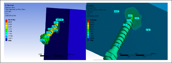
Stresses on the Alveolar Bone and the Screw at 0.5mm Insertion of the Mini Screw.
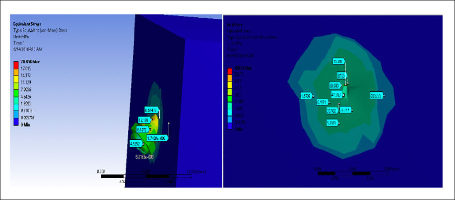
Stresses on the Alveolar Bone and the Screw at Full Insertion.
Results
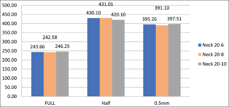
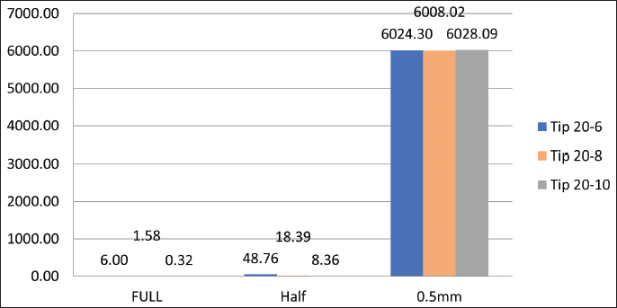
The results were analyzed using SPSS (version 20.0; SPSS, Chicago, Illinois, USA) and one-way analysis of variance (ANOVA) was tabulated using the general post-processor of ANSYS. On the body of mini-screws tested, the magnitude of maximum stresses at 0.5 mm, half length, and full-length insertion with torque were [for 10 Ncm (6 mm, 348.55, 344.14, 14.58 MPa) (10 mm, 351.12,345.69, 3.81 MPa)] and [for 20 Ncm (6 mm, 697.32, 687.95, 37.01 MPa), (10 mm, 696.85, 689.16, and 7.70 MPa)], respectively. On the neck of mini-screws tested, the magnitude of maximum stresses at 0.5 mm, half length, and full-length insertion with torque were [for 10 Ncm (6 mm, 197.9, 216.27, 123.93 MPa) (10 mm, 199.17, 216.22, 123.64 MPa)] and [for 20 Ncm (6 mm, 395.26, 430.10, 243.66 MPa), (10 mm, 397.51, 420.10, and 246.25 MPa)], respectively. On the tip of mini-screws tested, the magnitude of maximum stresses at 0.5 mm, half length, and full-length insertion with torque were [for 10 Ncm (6 mm, 3004.54, 22.22, 4.52 MPa) (10 mm, 3013.83, 4.18, 0.05 MPa)] and [ for 20 Ncm (6 mm, 6024.30, 48.76, 6.00 MPa), (10 mm, 6028.09, 8.36, and 0.32 MPa)], respectively.
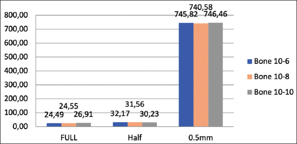
The stress levels at the bone with different lengths of mini-screws and under different force magnitudes are shown in Figures 7 and 8. The stresses increased to almost double their value when the insertion torque was doubled, showing a direct correlation in all the mini-screw lengths tested. For instance, for 10 Ncm of torque, the magnitude of maximum stresses on the bone when the mini-screw was 0.5 mm inserted in the bone recorded was 746.46 MPa, and when it was half length inserted in the bone was 30.23 MPa, while when it was full length inserted in the bone was 26.91 MPa. For 20 Ncm, the magnitude of maximum stresses on the bone when the mini-screw was 0.5 mm inserted in the bone recorded was 1483.11 MPa, and when it was half-inserted in the bone was 52.65 MPa, while when it was full length inserted in the bone was 49.52 MPa (Figures 6–13).
Bar Graph showing Stress Analysis on the Bone When Mini-Screws of Different Lengths Were Inserted Using 10 Ncm Insertion Torque.
Bar Graph Showing Stress Analysis on the Body of Different Lengths of Screws at Different Levels of Insertion With Force Magnitude of 20 Ncm Torque.
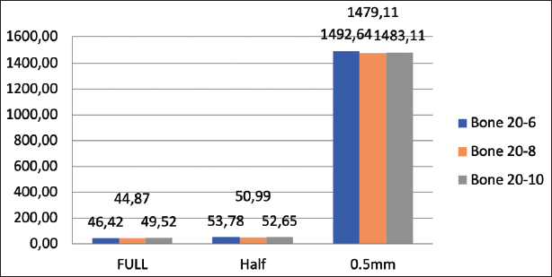
Bar Graph Showing Stress Analysis on the Body of Different Lengths of Screws at Different Levels of Insertion with Force Magnitude of 20 Ncm Torque.
Bar Graph Showing Stress Analysis on the Body of Different Lengths of Screws at Different Levels of Insertion with Force Magnitude of 20 Ncm Torque.
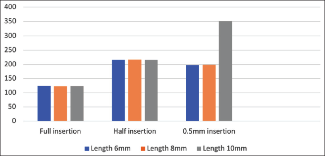
Bar Graph Showing Stress Analysis on the Neck of Different Lengths of Screws at Different Levels of Insertion with Force Magnitude of 20 Ncm Torque.
Bar Graph Showing Stress Analysis on the Tip of Different Lengths of Screws at Different Levels of Insertion with Force Magnitude of 10 Ncm Torque.
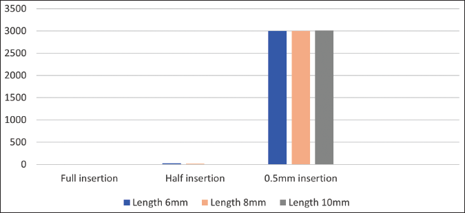
Bar Graph Showing Stress Analysis on the Tip of Different Lengths of Screws at Different Levels of Insertion with Force Magnitude of 10 Ncm Torque.
One-way ANOVA was carried out to determine whether there were any statistically significant differences between the means of the three screws of different lengths under 10 and 20 Ncm forces. According to p values, there was a significant difference between the stresses on the bone when the screws were inserted full and half their lengths using two different torque values of 10 and 20 Ncm, respectively. It was seen that with p values of less than .5, there was a higher standard deviation between fully inserted and half inserted mini-screws, which suggested that as the position decreased, the values became more dispersed (Figures 2–6).
Discussion
The objective of the present study was to carry out a biomechanical analysis of mini-screws at different levels during insertion, namely, at the point of insertion, at half insertion, and when completely inserted. The current study results showed no significant difference in the stresses generated across the body and the neck of 6, 8, and 10 mm length of implants for full, half, and 0.5 mm depth of insertion. It was seen that there was only a significant difference for full implant insertion at the three bone levels when the force level was 10 Ncm. There was an inverse relationship between the length of the mini-screws and the resulting stress on the bone when the force was 10 Ncm since the highest stress appeared at (14.58 Mpa) with 6 mm long and the minimum stress on the bone (3.81 Mpa) appeared when longer implant had been used. It was seen that the tip of the implant showed highly significant stresses when they were half or fully inserted into the bone but no significance when they were inserted only up to 0.5 mm. It was seen that there was a direct relationship between the force applied and the stresses on the body, the neck, and the tip of the implant at different implant lengths. As the force increased, the stress increased, and there was an inverse relationship between the stress and the length of the implant, as the length increased the stress decreased. The biomechanical success of a mini-screw is mainly dependent on the transfer of mechanical stresses from the screw to the adjacent bone. 15 These stresses should be of a magnitude sufficient to ensure success. If these are extremely high, it may lead to necrosis of the surrounding tissues, and if too low, it may result in poor osseointegration.16, 17
The diameter of the mini-screws in this study was kept constant, as previous studies have evaluated the effects of an increase in diameter on Von Mises stresses.2, 18–21 Since previous studies have shown that a 1.6 mm screw is three times less likely to fracture during placement compared to small diameter ones, this is the reason for deciding on a single diameter for the analysis. 18 The maximum generated stresses on the mini-screws and bone were found to be 14.58 and 3.81 Mpa, which are much lower than the individual threshold limits of 692 and 200 Mpa, respectively.22, 23
While there have been debates regarding the viability of FEA-based studies and their correlation with clinical behavior of various biomaterials, they have been found to be accurate in terms of results.7, 24 The overall results of this study depicted an interactive reaction demonstrated by the mini-screws and the bone. Previous studies have evaluated the association between the characteristics of mini-screws and stresses on the bone adjacent to the screws. Similar to the previous studies conducted by Dubais et al., mini-screw length affected the stresses during insertion.25, 26
Results from previous studies have demonstrated that the length and diameter of an implant have a direct effect on the stability.27, 28 Although biological materials are anisotropic and non-uniform, previous studies show that when the deformation is small in magnitude, finite element studies can be conducted using isotropic and homogenous properties. 29
A major limitation of this study was that the results were obtained using a three-dimensional
Model, which is although, similar in behavior, but do not replicate a clinical scenario. In a clinical setting, there are various factors responsible for successful placement of a mini-screw, such as bone density, age, gender, and periodontal health. Also, many parameters related to the mini-screw such as the thread pitch, width, and depth can be studied in the future.
Conclusion
Based on the findings of the study, the following are concluded:
On applying a load of the same intensity on different sizes, similar stresses were observed in mini-screws of 6, 8, and 10 mm in length.
On application of forces of 10 and 20 Ncm, the stress levels increased linearly when there was a change in the length.
A significant difference in the stresses generated on the mini-screws only when they were fully inserted inside the mandible.
As the lengths of the mini-screws increased, the stress decreased establishing an inverse relationship between them.
A direct relationship between the applied force and the stresses observed as an increase in the former led to a subsequent increase in the latter.
Footnotes
Declaration of Conflicting Interests
The authors declared no potential conflicts of interest with respect to the research, authorship, and/or publication of this article.
Ethical Approval
All procedures followed were following the ethical standards of the responsible committee on human experimentation and with the Helsinki Declaration of 1975, as revised in 1983.
Funding
The authors received no financial support for the research, authorship, and/or publication of this article.
Informed Consent
The participant has consented to the submission of the article to the journal.