
Abstract
Advanced imaging techniques have made available extensive three-dimensional microvascular network structures. Simulation of oxygen transport by such networks requires information on blood flow rates and oxygen levels in vessels crossing boundaries of the imaged region, which is difficult to obtain experimentally. Here, a computational method is presented for estimating blood flow rates, oxygen levels, tissue perfusion and oxygen extraction, based on incomplete boundary conditions. Flow rates in all segments are estimated using a previously published method. Vessels crossing the region boundary are classified as arterioles, capillaries or venules. Oxygen levels in inflowing capillaries are assigned based on values in outflowing capillaries, and similarly for venules. Convective and diffusive oxygen transport is simulated. Contributions of each vessel to perfusion are computed in proportion to the decline in oxygen concentration along that vessel. For a vascular network in the mouse cerebral cortex, predicted tissue oxygen levels show a broad distribution, with 99% of tissue in the range of 20 to 80 mmHg under reference conditions, and steep gradients near arterioles. Perfusion and extraction estimates are consistent with experimental values. A 30% reduction in perfusion or a 30% increase in oxygen demand, relative to reference levels, is predicted to result in tissue hypoxia.
Introduction
Delivery of oxygen throughout the body is an essential function of the circulatory system. The maximum distance that oxygen can diffuse from blood into tissue is generally in the range of 20 µm to 100 µm, depending on the oxygen consumption rate.1,2 The blood vessels forming the microcirculation transport oxygen by convection to within a short distance of oxygen-consuming cells. Multiple mechanisms including angiogenesis, structural remodeling and blood flow regulation are responsible for ensuring that the microvascular structure is adequate and that blood flow is distributed and regulated according to local needs.3,4 Impairment of these mechanisms plays a role in many pathologies, including neurodegenerative diseases, heart disease and sepsis.5–8 Understanding these phenomena requires consideration of network-level microvascular functions. 9
A number of imaging techniques are available to provide information on the three-dimensional structure of microvascular networks, 10 including scanning electron microscopy of corrosion casts,11,12 reconstruction from serial sections,13–16 confocal and multiphoton imaging, 17 micro-CT imaging18–20 and optical coherence tomography. 21 Some of these techniques allow imaging down to the capillary scale in regions with overall dimensions of order 1 mm or more, containing thousands of vessel segments. Quantitative structural information about microvascular networks can be derived from these images, including positions, lengths, diameters, and topological connectivity of vessel segments.22–24
The rate of convective delivery of oxygen by blood vessels depends on blood flow. In thin sheet-like tissues, such as the mesentery, techniques are available to measure flow rates or red blood cell fluxes throughout extensive networks. 25 In other tissues, such as brain or myocardium, flow rates can be measured in at most a small subset of vessels. 26 For such cases, methods have been developed 27 to obtain estimates of flow rates throughout the network.
The short diffusion distances of oxygen imply the existence of steep oxygen gradients in tissue, over scales of tens of µm. Experimental methods for measuring tissue oxygen levels, including microelectrodes and phosphorescence quenching, have limited ability to resolve spatial distributions on these scales, particularly in three dimensions. 28 Theoretical models can be used to estimate tissue oxygen distributions. 29 Such models simulate convective transport within blood vessels and diffusion from blood to surrounding tissue. The Green’s function method30,31 has been developed to allow computationally efficient simulations with extensive, geometrically realistic network structures.
In many tissues of interest, including brain, the microvessels form a continuous three-dimensional mesh throughout the tissue. When the microvascular structure of an imaged region (referred to as the “simulation region”) is observed, many vessels cross the boundaries of the region, in addition to the main feeding and draining vessels. This creates a challenge when simulating oxygen transport by such networks, since oxygen levels must be specified in all vessels entering the simulation region. Major feeding arterioles may be assumed to receive arterial blood with high oxygen saturation, but this assumption is not appropriate for capillaries and venules. Furthermore, when analyzing effects of changing blood flow rate or oxygen consumption rate, fixed levels of oxygen in inflowing vessels cannot be assumed, since their oxygen content should depend on the perfusion and the oxygen consumption rate. One objective of the present work is to develop a physiologically realistic method for assigning oxygen levels to inflowing vessels for simulations of oxygen transport.
The presence of a large number of vessels that cross boundaries of sample tissue regions creates a further challenge, with regard to the estimation of tissue perfusion, defined as blood flow rate per unit tissue volume. When regions of different sizes are sampled, the number of inflowing vessels crossing the region’s boundaries, and hence also the total flow rate entering the region are approximately proportional to the surface area of the region. If this flow rate is used to estimate perfusion, it is divided by the volume of the region. For a region of a given shape and with linear dimension L, the surface area is proportional to L2 and the volume is proportional to L3. As a consequence, the estimated perfusion is approximately proportional to 1/L. 32 For small regions, the resulting estimates are much higher than estimates based on overall flow to an organ or tissue. A second objective of the present work is therefore to develop a method for estimating tissue perfusion from data on flows in networks that gives consistent results independent of the size of the region.
To address these objectives for a given simulation region containing an extensive microvessel network, an approach is developed including the following steps. (i) Blood flow rates in all segments are estimated using a previously developed method. 27 (ii) Oxygen boundary conditions for inflowing vessels are estimated by classifying them as arterioles, capillaries or venules, and assigning oxygen concentrations for each category based on oxygen levels in corresponding outflowing vessels. (iii) Two “virtual regions” are constructed, an upstream region and a parallel region (Figure 1(a)), which together with the simulation region constitute a flow pathway from arteries to veins that is self-contained, in the sense that no blood flow is exchanged with other regions, except via the main feeding and draining vessels. (iv) Vessel and tissue oxygen levels in the simulation region are computed using a Green’s function method. (v) For each region, a measure of perfusion is defined based on the declines in oxygen concentration along flow pathways passing through that region. This approach is applied to a vascular network in the mouse cerebral cortex, yielding estimates of perfusion and oxygen extraction fraction that are consistent with experimental values, and allowing predictions of the effect of changes in perfusion or oxygen demand on the distribution of tissue oxygen levels.
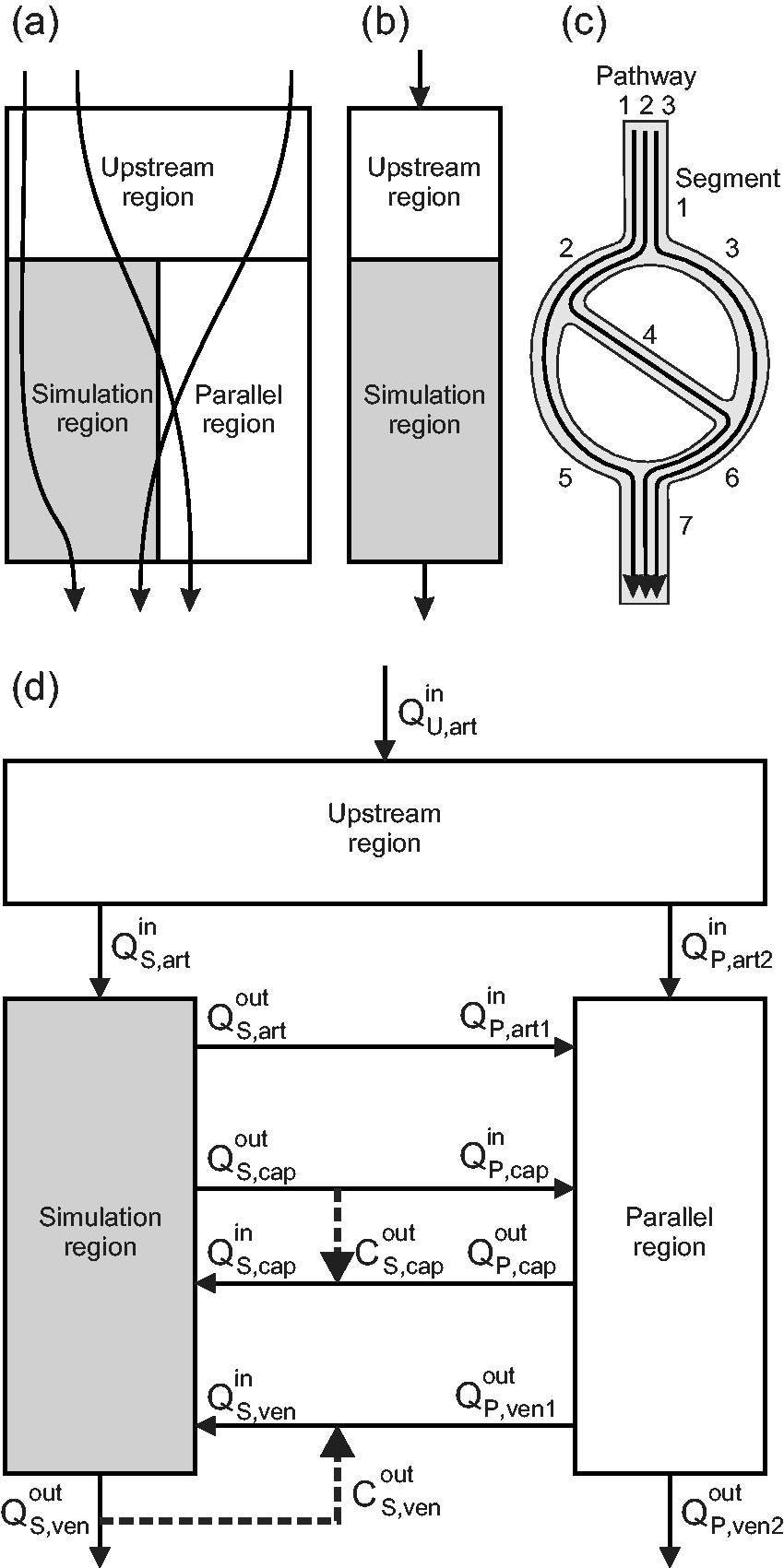
(a) Schematic illustration of flow pathways for blood entering and exiting the simulation region. (b) Schematic illustration of configuration used to define effective perfusion. (c) Relationship between flow pathways and segments in a simple network. The flow in segment 1 is the sum of the flows on pathways 1, 2 and 3, while the change in concentration on pathway 1 is the sum of the changes in segments 1, 2, 5 and 7. (d) Schematic illustration of configuration including simulation, upstream and parallel regions. Solid lines represent blood flows in and out of each region. Heavy dashed lines represent assumptions on oxygen concentrations of blood in capillaries and venules entering the simulation region. See text for details.
Methods
Estimation of blood flow rates
The network structure is represented as a set of cylindrical segments with known lengths and diameters, meeting at a set of nodal points. The flow resistance of each segment, defined as the ratio of the pressure drop along the segment to the blood flow rate, is estimated using Poiseuille’s law with an effective viscosity dependent on tube diameter and hematocrit.33,34 If conditions on pressure or flow were specified at every boundary node of the network, along with hematocrits at all inflow nodes, then the flows in all internal segments could be predicted using established theoretical models.33,35 Typically, however, such information is unavailable or insufficient. Fry et al.
27
developed a method to obtain physiologically reasonable estimates of flow rates throughout the network by minimizing the summed deviations of pressures and wall shear stresses from target values estimated from observations of blood flow in microcirculation. In this method, the quantity

In the present work, this method is further developed in several ways. (i) An option is introduced to specify the flow directions in boundary segments, without defining the flow rate. Even in the absence of flow information, specification of the flow directions in the main feeding and draining vessels makes the method more robust by avoiding the possibility of predicting reversed flow directions in large parts of the network. Such specification can be based on anatomical features or on oxyhemoglobin saturation levels. (ii) Improved computational speed for large N is obtained by using iterative methods that take advantage of the sparseness of the system, namely the conjugate gradient method and the relaxation method.
37
(iii) A factor κ is introduced to compensate for a bias in the least squares method, which arises because any solution for the flows can be multiplied by an arbitrary scaling factor and still satisfy conservation of flow at all interior nodes. Suppose that τi is a random variable, τ0 is the target value of its mean
Classification of boundary flows for the simulation region
In assigning oxygen levels to vessels entering the simulation region, different classes of microvessels must be distinguished. For instance, the assumed oxygen content should be lower in an inflowing venule or capillary than in an arteriole. In the present method, all inflowing and outflowing boundary segments are classified as arterioles, capillaries or venules, giving six classes of boundary vessels. In the first step of this classification, boundary vessels with diameters below a threshold value (here 8 µm) are identified as capillaries. The second step requires consideration of the pressures at the boundary nodes of the network, which are computed during the estimation of the blood flows in the network. First, the mean pressure of all capillaries is computed. Then, non-capillary vessels are classified according to the pressure at their boundary nodes: if the pressure exceeds the mean capillary pressure, they are classified as arterioles, otherwise as venules. This procedure ensures that arterioles are generally upstream of capillaries and venules are generally downstream of capillaries.
Assignment of oxygen boundary conditions for the simulation region
The set of outflowing capillaries is assumed to be representative of the inflowing capillaries with regard to oxygen content. The oxygen concentrations of inflowing capillaries are therefore set equal to the flow-weighted mean of the concentrations in outflowing capillaries. For the venules, the distributions of oxygen concentrations in inflow and outflowing vessels are not necessarily equivalent. However, changes in oxygen content occurring along venules are generally small, and can be positive or negative. 38 Therefore, the oxygen concentrations in inflowing venules are set equal to the flow-weighted means of the concentrations in the outflowing venules. For inflowing arterioles, the oxygen concentrations are calculated from the outflow of the upstream region, as described below. In this scheme, the conditions imposed on inflowing vessels depend on the estimated oxygen concentrations in outflowing vessels, which are themselves influenced by the assumed inflow conditions. Consequently, an iterative method is used to obtain the oxygen boundary conditions, as described below.
Simulation of oxygen transport in the simulation region
Within the simulation region, the spatially varying tissue PO2, P(x,y,z), satisfies
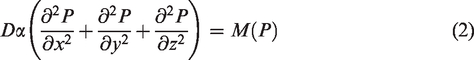
These equations are solved numerically using the Green’s function method as described previously30,31 and summarized here. The vessel network is subdivided into many short pieces, and for each piece, the Green’s function, i.e. the PO2 field resulting from a source of unit strength, is defined for an infinite spatial domain. The use of an infinite domain avoids artifacts that arise at the boundaries if a finite domain is assumed. 31 Oxygen consumption is represented by a cubic array of sinks in the tissue region, and the Green’s function is similarly defined for these sinks. The PO2 at any point can be expressed in terms of the strengths of these sources and sinks and the Green’s functions. The source and sink strengths are computed to satisfy discretized forms of the governing equations.
The solution to this system depends on the assumed oxygen concentrations in the inflowing vessel segments. Initially, these concentrations are set to arbitrary values and the simulation is run. From the resulting concentrations in the outflow vessels, the inflow boundary conditions are updated as described in the previous section, and the simulation is repeated. This process is continued until the boundary conditions converge within a specified tolerance, which normally requires less than 10 iterations.
Definition of effective perfusion for small tissue regions
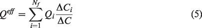
A goal of this work is to develop a method for estimating the perfusion of small tissue regions, so that the results are consistent with overall tissue perfusion. As mentioned previously, estimates of perfusion based on the total inflow to a region divided by its volume depend strongly on the size of the region. 32 Flow pathways that pass through a given region generally contribute to the perfusion of other regions (Figure 1(a)). Therefore, the flow on a pathway should not be fully attributed to one region, but should be apportioned among the regions through which it passes. In previous work, 12 we addressed this issue by considering the fraction of the overall pathway length that lies within the region. Here, a different approach is presented. The flows through a region can be represented as a superposition of flows along a number of unbranched pathways through the region. 12 We define the “effective flow” of a region as the sum of the flows on these pathways, each flow being first multiplied by the change in oxygen concentration on that pathway within the region divided by the total change in oxygen concentration from arteries to veins. The effective perfusion is then defined as the effective flow divided by the volume of the region.
The analysis leading to this definition is based on imposing the conditions that both the effective perfusion and the oxygen consumption rate per volume in individual regions (representing the microscale) should equal those in the combined regions (representing the macroscale). To demonstrate the implications of these conditions, we consider first a simple system consisting of an upstream region with volume VU connected in series with a simulation region with volume VS (Figure 1(b)), with a blood flow rate Q passing through both regions. Steady-state (or quasi-steady-state) conditions are assumed. The overall decrease in oxygen concentration is written as the sum of the decreases in the upstream and simulation regions, i.e.
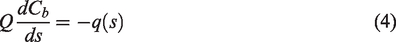
This definition of perfusion can be extended to configurations with any number of regions and flow pathways. Consider a region traversed by Nf flow pathways, each of which has a flow Qi and an associated change ΔCi in oxygen concentration. If the overall decline in oxygen concentration from arteries to veins is ΔC, then according to the above definition, the effective flow rate is
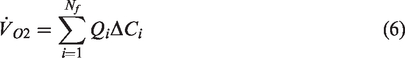
Under steady-state conditions, the total consumption rate must equal the total rate of oxygen delivery to the region, i.e.
For computational purposes, the network is represented as a set of segments rather than as a set of pathways. Figure 1(c) illustrates the relationship between pathways and segments. If Ns is the number of segments, each of which has a flow
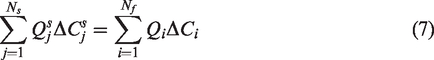
This relationship can be demonstrated by writing the flow
System with upstream and parallel regions
As an illustration of the approach presented above, the simulation region containing the observed network is combined with parallel and upstream “virtual” regions (Figure 1(d)) to obtain a self-contained flow system. The parallel and upstream regions have defined volumes, blood flows and oxygen consumption rates, but their vascular structure is not specified. In general, the simulation region has arteriolar outflows and venular inflows, and the inflow and outflow rates in capillaries do not balance. The inclusion of the parallel region results in a combined system that has only arterial inflows and venous outflows. Any inequality between the arteriolar inflows and the venular outflows is balanced by an inflow or outflow of the parallel region. The upstream region is introduced to allow for cases in which the arteriolar inflow to the simulation region has significantly lower oxygen concentration than arterial blood. A corresponding downstream region is not needed, because oxygen exchange by venules and veins is assumed to be small.
To describe oxygen transport in this configuration, we define blood flow rates
The volumes and consumption rates of the upstream and parallel regions can be calculated based on the stated assumptions. To match the parallel region with the simulation region, the conditions

Similarly, the volume

This analysis provides a mathematically precise relationship between the flows in a representative tissue region and the perfusion of a larger region fed by arterial blood and drained by venous blood. It shows that the effective perfusion of the simulation region as defined here equals the overall perfusion as conventionally defined. Two further points should be noted. Firstly, this result does require the assumptions that
Summary of method
The approach for simulating blood flow and oxygen transport in a microvascular network with specified geometry is summarized in Figure 2. Flow rates throughout the region are estimated as described previously.
27
Given vessel flow rates and nodal pressures, the boundary segments are classified as arterioles, capillaries or venules. To initialize the oxygen simulations, the concentrations
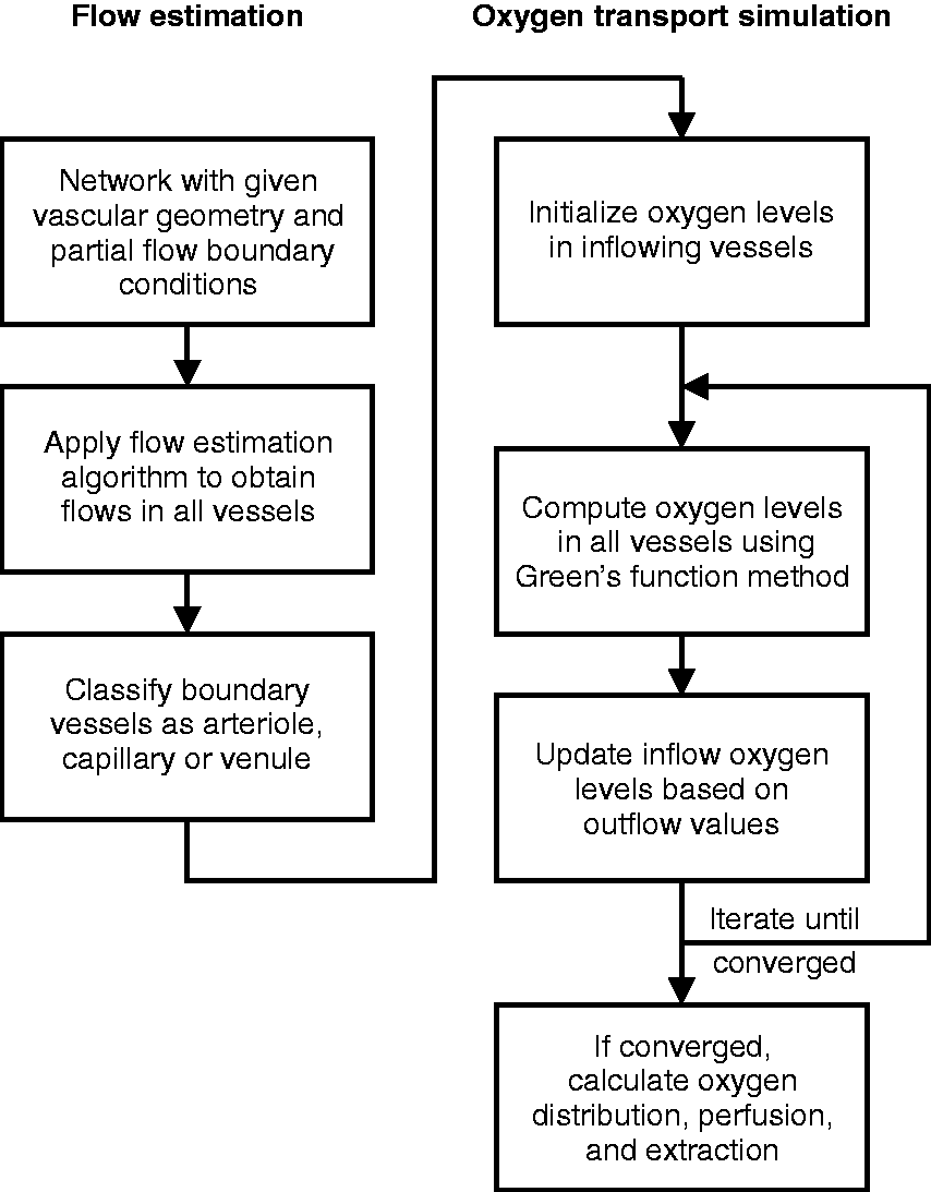
Flow chart of method for assigning blood flow rates and boundary conditions for simulation of oxygen transport in regions with defined microvascular network structures.
Application to a microvascular network in mouse brain cortex
Gagnon et al. 41 reported observations of the microvascular network in a region approximately 600 × 600 × 660 µm of mouse cerebral cortex, in which the vascular structure was obtained by two-photon microscopy of fluorescently labeled vessels. The original image stack was here reanalyzed to obtain a structure with 4908 segments and 4126 nodes, including 208 terminal segments, nearly all of which lie close to the region boundaries, and with geometrical characteristics as shown in Table 1. Based on the published observations of this network, 41 flow directions were assigned to 12 boundary segments having diameters greater than 15 µm.
Reference parameter values.
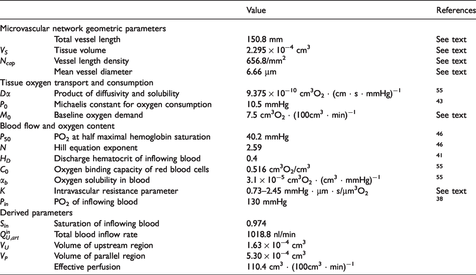
Parameters were chosen to represent typical conditions in the normal mouse cerebral cortex (Table 1). Values are given to 3 or 4 significant figures to maintain internal consistency in the calculations, even if not known to corresponding accuracy. The oxygen diffusivity and solubility in tissue are based on measurements made at body temperature.
42
In previous work,
12
the Michaelis constant for oxygen uptake was assumed to be 1 mmHg. In the present study, a higher value, 10.5 mmHg, is assumed, based on in vivo studies.
43
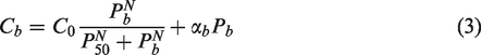
As a consequence, the oxygen consumption rate according to Michaelis–Menten kinetics is significantly less than the oxygen demand, even at typical levels of tissue PO2. The reference oxygen demand M0 was chosen to yield oxygen consumption rates CMRO2 of about 6 cm3O2 · (100 cm3 · min)−1, similar to observed values in non-anesthetized mice.44,45 The oxygen binding characteristics of hemoglobin are represented by the Hill equation, with coefficients specific for C57BL/6 mice.
46
The Green’s function method includes effects of intravascular resistance to oxygen diffusion, according to the equation
31
Results
Figure 3(a) shows the structure of a microvessel network in mouse brain cortex 41 used in the present simulations. The flow directions in the main feeding arterioles and venules were specified based on experimental observations. Flows in all segments were estimated according to the algorithm as described above. The resulting mean flow velocities are shown by the color coding in Figure 3(a), and their distribution, ranging from below 0.01 mm/s to above 10 mm/s, is indicated in Figure 3(e). Flow rates (Figure 3(c)) ranged from below 0.1 nl/min to above 100 nl/min. Nodal pressures (Figure 3(b)) show a peak around the target value of 31 mmHg, with higher values in feeding vessels. The pressure-dependent target values for wall shear stress ranged from 17 to 97 dyn/cm2. As Figure 3(d) shows, the wall shear stresses obtained by this method are clustered around this range, but with some higher and lower values.
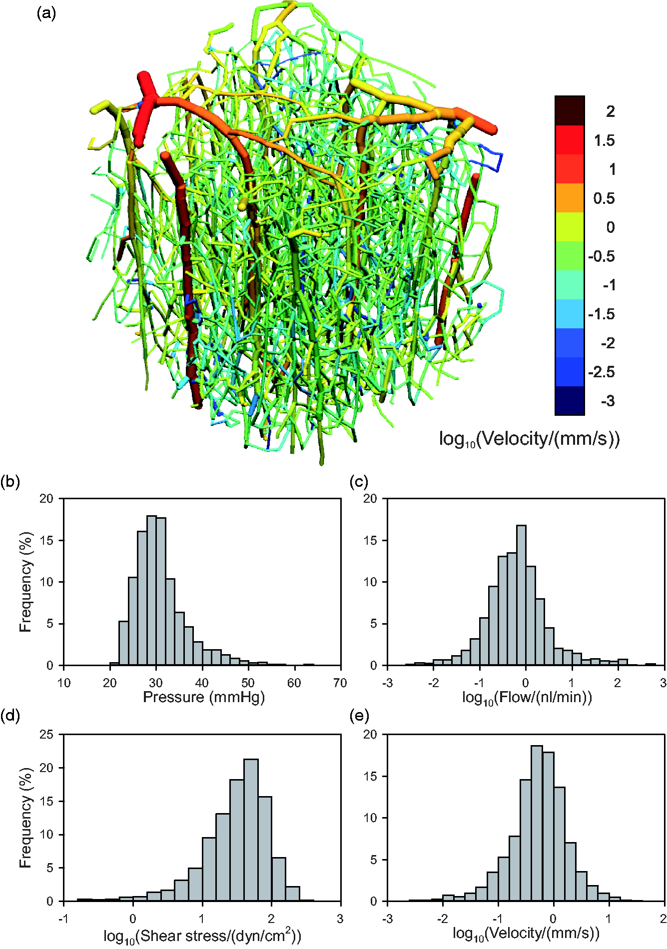
Results of flow estimation algorithm. (a) Vascular network, color-coded by mean blood flow velocity according to scale at right. (b–e) Histograms showing distributions of segment flow parameters, weighted according to segment length. (b) Intravascular pressure. (c) Flow rate (log scale). (d) Shear stress (log scale). (e) Mean flow velocity (log scale).
Results of the simulation of oxygen transport are shown in Table 1 and in Figure 4. Under the assumed reference conditions, the estimated inflow PO2 values for capillaries and venules are 52.6 mmHg and 56.8 mmHg, respectively. The sum of the volumes of the simulation, upstream and parallel regions (Table 1) is 922 nl, or approximately four times the volume of the simulation region. The computed distributions of vessel and tissue PO2 are illustrated in Figure 4. Vessel levels are indicated in Figure 4(a), and Figure 4(b) shows tissue levels on the slice labeled A-A in Figure 4(a). Histograms of vessel and tissue PO2 (Figure 4(c) and (d)) show broad distributions, with higher average values in vessels (55 mmHg) than in tissues (47 mmHg), as expected. For the assumed reference values of the parameters, PO2 levels at virtually all points in the tissue and the vessels are at least 20 mmHg. Most tissue PO2 values (99%) are below 80 mmHg. These results are for the simulation region and do not reflect heterogeneity that may be present on larger spatial scales, which would result in broader distributions of tissue PO2.
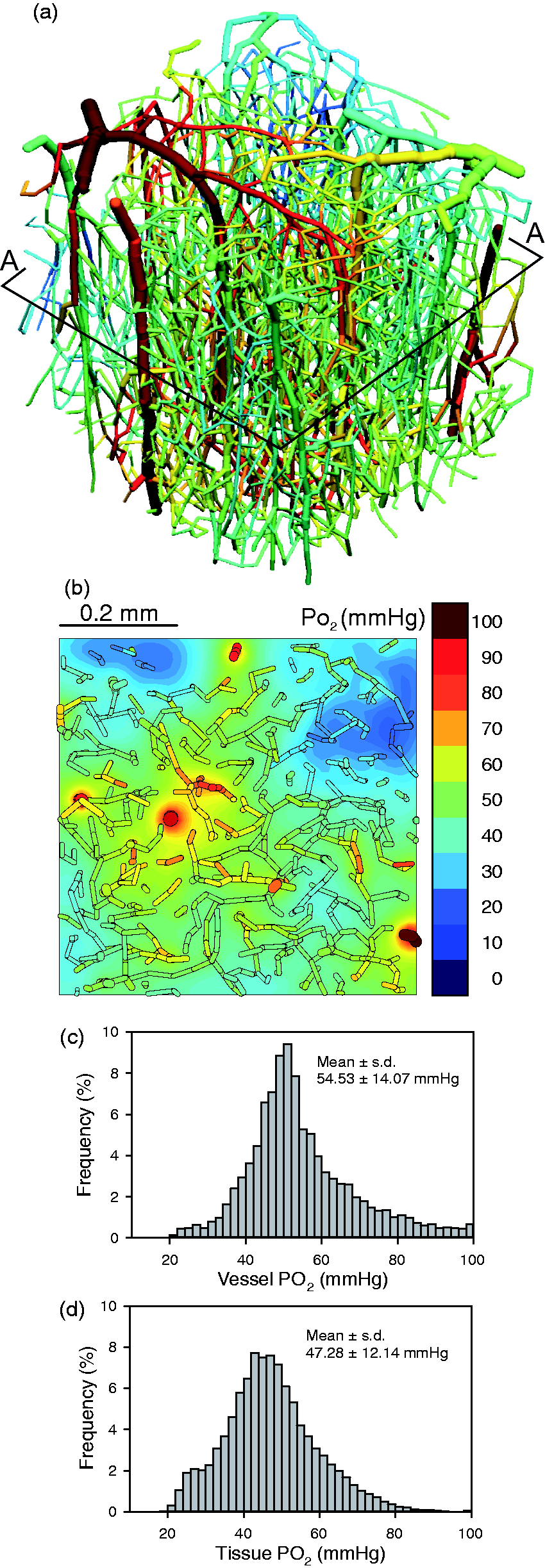
Results of oxygen transport simulation, under control conditions, with arterial PO2 = 130 mmHg. (a) Vascular network, color-coded by vessel PO2 according to scale in (b). A-A indicates plane on which contours of tissue PO2 are computed. (b) Distribution of tissue PO2 in plane section A-A. Segments lying within 50 mm of the plane section are included to show relationship between vessels and tissue oxygen levels. (c) Histogram showing distribution of vessel PO2. (d) Histogram showing distribution of tissue PO2.
This method allows exploration of the effects of varying oxygen transport parameters on the distributions of vessel and tissue PO2. Effects of reducing arterial PO2 below the reference value of 130 mmHg are shown in Figure 5. Levels of vessel PO2 are shown corresponding to the flow-weighted averages of oxygen concentration. As expected, the arteriolar inflow PO2 (i.e. that of blood exiting the upstream region) declines in parallel with arterial PO2. Oxygen levels in vessels and tissue decline slightly as arterial inflow PO2 is reduced from the reference level of 130 mmHg to 65 mmHg, because arterial saturation remains relatively high in this range. The decline in tissue and vessel PO2 is more pronounced at lower levels of arterial PO2. The computed inflow PO2 values in capillaries and venules,
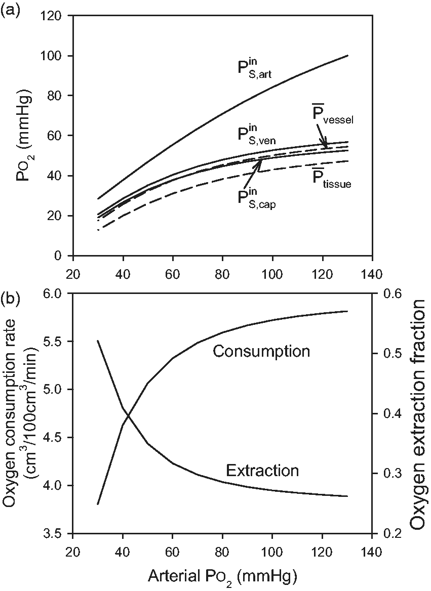
Effect of varying arterial PO2 on oxygen transport parameters. (a) Levels of PO2 in vessels entering the simulation region (arterioles:
Effects of varying both blood flow rate and oxygen demand are examined in Figure 6, for arterial PO2 fixed at the reference value. Figure 6(a) shows that mean tissue PO2 decreases with increasing oxygen demand and increases with increasing blood flow, as expected. Figure 6(b) shows the variation of tissue hypoxic fraction, defined as the percentage of tissue with PO2 below 10.5 mmHg. This is the level at which oxygen consumption falls to 50% of demand, according to the assumed Michaelis–Menten kinetics. With increasing oxygen demand, hypoxia first appears when oxygen demand reaches 10 cm3O2 · (100 cm3 · min)−1, a 30% increase. Alternatively, with variation of perfusion, hypoxia first appears when perfusion is reduced by 30%, relative to the assumed reference conditions.
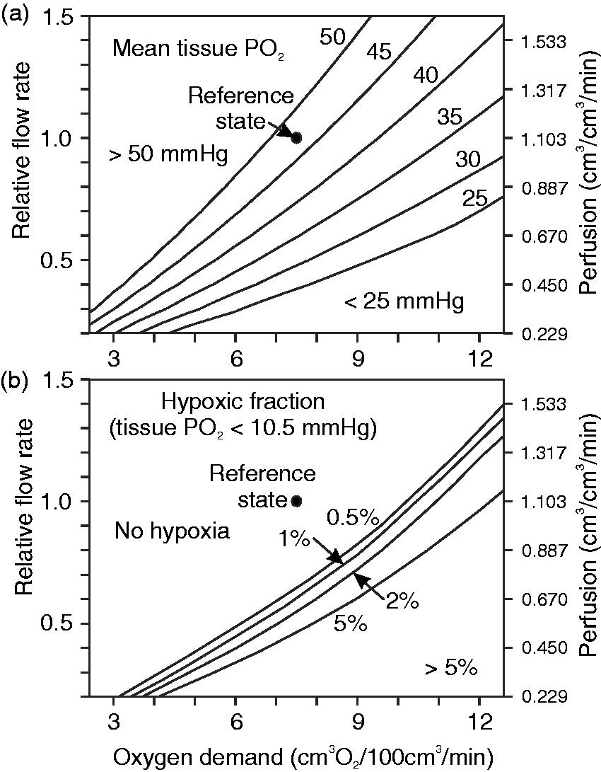
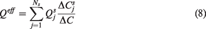
Contour plots showing effects of varying blood flow rate and oxygen demand on tissue hypoxic fraction and on mean tissue PO2. Left-hand axes show flow rate relative to reference value. Right-hand axes show approximate values of effective perfusion for each relative flow rate. Effective perfusion is calculated according to equation (8) and is not exactly proportional to blood flow rate. (a) Mean tissue PO2. (b) Hypoxic fraction, defined as percentage of tissue points below the assumed Michaelis constant for oxygen uptake (10.5 mmHg).
Discussion
Despite advances in imaging of the microcirculation of the brain and other tissues, the ability to draw conclusions about tissues’ functional status from such data has been limited. Oxygen delivery is the most critical function of the microcirculation, and vascular network structure strongly influences oxygen transport. Theoretical methods have been developed for simulating blood flow and oxygen transport in networks with prescribed geometries.29,33 These methods require information about flow conditions and oxygen levels in vessels that cross the domain boundaries, which is generally difficult or impossible to obtain. In the absence of such information, blood flow and oxygen content cannot be accurately predicted in each individual vessel segment. One way to circumvent this problem is to use homogenization methods, in which the microvasculature is replaced by a porous medium with a permeability derived from the typical microvascular structure.47,48 Hybrid approaches, combining explicit network structures with a continuum representation of the smallest vessels, have also been used.49–51 The approach taken here uses an explicit representation of the network structure down to the capillary level. Information about typical distributions of hemodynamic and oxygen transport variables in the microcirculation, combined with the physical principles governing blood flow and oxygen transport, is used to obtain physiologically realistic solutions, and thereby estimate key properties of the resulting tissue oxygen field.
A further challenge in analyzing oxygen transport in microvascular networks is the problem of relating microscale and macroscale parameters. In particular, estimation of perfusion based on the total blood flow rate entering a micro-region leads to inconsistent results. 32 Here, we present a novel method to solve this problem, based on simulation of oxygen transport in the region. In this method, the effective blood flow is computed as the sum of the flows in each vessel multiplied by the decline in oxygen concentration along that vessel divided by the overall artery-to-vein decline in oxygen concentration. The effective perfusion is calculated by dividing this effective flow by the volume of the region. The analysis presented here shows that this estimate is unbiased, in the sense that when the simulation region is combined with parallel and upstream regions, all three regions having the same volume-specific oxygen consumption rate and perfusion, a complete self-contained flow pathway from arteries to veins is obtained.
Arteriovenous shunts may occur in the cortical vasculature, including pial vessels.52,53 Such shunts would result in reduced arteriovenous decline in oxygen concentration from arteries to veins (ΔC), and therefore, from equation (8), increase the estimated perfusion proportionately.
In this approach, the estimated effective perfusion depends not only on the blood flow rates, but also on predicted oxygen concentrations in vessels. Consequently, when blood flow or oxygen demand is varied, effective perfusion is not necessarily proportional to flow rate. The volume of the parallel region also varies with the assumed flow rate and oxygen demand, with values from 4.6 to 5.3 × 10⁻⁴ cm3 for the conditions examined here. However, when the flow rate was varied, the effective perfusion was found to be approximately proportional to the assumed flow rates, with a ratio varying by a few percent at most. Similarly, the effective perfusion for a given flow rate was found to vary only slightly (up to 3%) over a wide range of oxygen demand. Therefore, the effective perfusion as defined here closely reflects the blood flow rate to tissue, despite the fact that its definition depends on simulations of oxygen transport. An analogous definition of effective perfusion could be developed for any other solute that experiences significant extraction in a single pass through the tissue region. The resulting estimates would likely differ from those obtained based on oxygen transport.
To illustrate the application of this approach, a network derived from observations of the mouse cerebral cortex is used. Of 4908 segments in the discretized form of this network, 208 are boundary segments. The only explicit information about the flows and oxygen levels of these boundary segments used in the present analysis is the flow direction in the 12 largest boundary vessels, together with the PO2 value in the inflowing arterioles. This information was derived from experimental observations. 41 The other physiological input data to the model consist of the typical distribution of shear stress in microvascular networks as a function of intravascular pressure, and the typical capillary pressure. These values were derived from previous observations of blood flow distributions in rat mesentery networks, 27 as comparable data for brain microcirculation are not available. The overall flow characteristics resulting from these assumptions are consistent with known hemodynamic parameters of the mouse cortex. The mean vessel flow velocity was found to be 0.57 mm/s, similar to the mean value of approximately 0.7 mm/s in capillaries found by Li et al. 54
For the assumed reference state, the total of all inflows to simulation region was estimated as 1261.6 nl/min. If this flow is divided by the volume of the region, the resulting estimate of perfusion is 549.6 cm3 · (100 cm3 · min)−1, an unrealistically high value. The effective flow to the simulation region as defined in equation (5) was estimated as 253.5 nl/min, yielding an effective perfusion of 110.4 cm3 · (100 cm3 · min)−1, which is within the range of 75 to 125 cm3 · (100 cm3 · min)−1 reported in previous studies. 41 The oxygen extraction fraction involves the ratio of oxygen consumption rate to perfusion. If the perfusion is estimated from the entire flow entering the region, then the resulting estimate of extraction is unrealistically low, relative to values for the whole tissue. When the effective perfusion as defined here is used, the estimated oxygen extraction fraction is 26.2% for the reference state, similar to previous estimates for mouse cortex. 41 These results emphasize the importance of compensating for the effects of region size 32 when estimating perfusion based on microscale observations, and support the utility of the method used here.
The results depend on the assumptions used in estimating vessel flow rates by minimizing the quantity in equation (1). The key assumption is that wall shear stresses tend to follow an experimentally observed increasing functional relationship with intravascular pressures. 36 This behavior is a consequence of known structural adaptation responses of blood vessels, whose luminal diameters increase with increases in wall shear stress and decrease with increasing pressure. The pressure-dependent term in equation (1) penalizes large deviations in pressure, but does not strongly constrain the pressure distribution (Figure 3(b)). The estimates of perfusion by this method are particularly sensitive to vessel diameters, because the volume flow rate for a given target wall shear stress varies as the cube of diameter. Reliable estimates of diameters for all vessels, including capillaries, are therefore needed.
The present simulations were carried out assuming a fixed discharge hematocrit of 40% in all vessels. In reality, hematocrit varies in microvascular networks as a result of uneven hematocrit partition in diverging bifurcations. 35 The present approach could be modified to include this effect, with some additional complexity because the relationship between oxygen concentration and PO2 depends on hematocrit. Oxygen demand was assumed to be uniform in these simulations. The effects of variations in oxygen demand through the cortical layers 54 could be introduced into the computations in the simulation region, while maintaining consistency of average oxygen consumption rate with the parallel and upstream regions.
In the present approach, oxygen levels in inflowing capillaries were estimated as the average of those in the outflowing capillaries, and similarly for the inflowing venules. When oxygen transport parameters such as arterial PO2 are varied, the inflow PO2 values
The results in Figure 6 illustrate the application of this approach to investigate the variation of key parameters describing tissue oxygenation, with alterations in blood perfusion and oxygen demand. Comparison of the two panels in Figure 6 shows that hypoxia starts to appear when the mean tissue PO2 is in the range of 35 to 40 mmHg. This result emphasizes the importance of considering the heterogeneity of tissue PO2 levels when analyzing the conditions leading to tissue hypoxia.
In conclusion, a systematic approach is presented for investigating tissue oxygenation by extensive microvascular networks with defined geometries, which requires minimal information about conditions on the vessels that cross the domain boundaries. For a network derived from the mouse brain cortex, this approach yields a flow distribution that agrees with previous observations of hemodynamics in that tissue, and allows systematic predictions of the effects of varying blood flow, arterial oxygen level and oxygen demand on tissue oxygen levels. A novel definition of tissue perfusion is introduced that reconciles microscale and macroscale estimates of perfusion and oxygen extraction ratio. This approach has potential applications for functional assessment of microcirculation in normal and pathological conditions, in brain and in other tissues.
Footnotes
Funding
The author(s) disclosed receipt of the following financial support for the research, authorship, and/or publication of this article: Supported by NIH grants R01 HL070657, U01 HL133362, T32 GM008718, R01 NS091230 and R01 MH111359.
Declaration of conflicting interests
The author(s) declared no potential conflicts of interest with respect to the research, authorship, and/or publication of this article.
Authors’ contributions
JC, GL, AS and BL developed the approach and the computational methods. SS and DB provided the vascular geometry of mouse cortex and conceptual guidance. TS conceived and carried out the study and wrote the text. All authors edited the text.