
Abstract
Orthopedic medical devices are continuously evolving for the latest clinical indications in craniomaxillofacial, spine, trauma, joint arthroplasty, sports medicine, and soft tissue regeneration fields, with a variety of materials from new metallic alloys and ceramics to composite polymers, bioresorbables, or surface-treated implants. There is great need for qualified medical device pathologists to evaluate these next generation biomaterials, with improved biocompatibility and bioactivity for orthopedic applications, and a broad range of knowledge is required to stay abreast of this ever-changing field. Orthopedic implants require specialized imaging and processing techniques to fully evaluate the bone-implant interface, and the pathologist plays an important role in determining the proper combination of histologic processing and staining for quality slide production based on research and development trials and validation. Additionally, histomorphometry is an essential part of the analysis to quantify tissue integration and residual biomaterials. In this article, an overview of orthopedic implants and animal models, as well as pertinent insights for tissue collection, imaging, processing, and slide generation will be provided with a special focus on histopathology and histomorphometry evaluation.
Keywords
The diversity of indications and materials utilized for orthopedic medical devices have greatly expanded in recent years. This expansion is due to both new technologies and reformulation of preexisting materials. For conducting safety and efficacy testing of orthopedic devices, it is paramount to count on the combination of a highly skilled technical team to generate excellent quality histology slides and an experienced pathologist to evaluate the tissue response to the presence of the implant and to assess the sites for evidence of adverse effects or safety concerns. The histopathological evaluation needs to be tailored to each individual orthopedic device study in order to assess every applicable end point, utilizing a qualitative and/or semiquantitative evaluation (via histopathology) and a quantitative evaluation (via histomorphometry) to fully characterize the healing response. Obtaining valuable insight from the technical team and pathologist prior to starting the animal studies is important to determine the necessary necropsy, fixation, imaging, sectioning, processing, histopathological, and histomorphometry end points.
Definitions and Types of Orthopedic Materials
Several definitions for orthopedic applications are as follows: osteoinduction is the promotion of undifferentiated cells into preosteoblasts to generate new bone growth. Osteoconduction is the ability of an implant material to support bone growth directly on the implant surface or within the implant’s porous structure, depending on the biomaterial type. Osseointegration is the formation of bone directly on an implant surface without fibrous tissue intervening between the newly mineralized bone and the implant surface (Albrektsson and Johansson 2001).
Scaffolds for orthopedic uses can come from multiple sources. Autograft (i.e., bone harvested from the animal to serve as a bone filler) is considered to be both osteoconductive and osteoinductive by nature (Cypher and Grossman 1996), and allograft (i.e., bone harvested from a donor) has several potential issues of supply limitation, the potential for disease transmission, and possibly rejection by the recipient’s immune system. Bone graft substitutes consisting of either demineralized bone matrix or collagen are typically osteoconductive and sometimes osteoinductive, while synthetic bone graft substitutes (e.g., ceramic material) are typically osteoconductive but not osteoinductive when used alone. When biologic material such as bone marrow aspirate, demineralized bone matrix, or growth factors (e.g., bone morphogenic proteins) is combined with a synthetic material, this often adds osteoinductive and/or osteogenic properties, thereby cultivating a similar healing response as an autograft without the comorbidity associated with autograft harvesting (Giannoudis, Dinopoulos, and Tsiridis 2005).
Orthopedic implants typically can be biostable (i.e., inert with minimal foreign body reaction), bioactive (i.e., eliciting a specified cellular response), bioabsorbable, or can have a combination of bioactive and bioabsorbable properties. Biostable implants tend to form a layer of nonspecific proteins on the surface, resulting in fibrous encapsulation of the implant. These implant types are commonly metallic (titanium and titanium alloys, stainless steel, cobalt–chromium, or tantalum, with or without surface treatments or coatings to promote osseointegration), ceramic (alumina, zirconia, or porous ceramics), or polymers (polyethylene such as ultrahigh molecular weight polyethylene, acrylic resins, polyurethane, polypropylene, or polymethylmethacrylate [PMMA]), and polymer composites such as polyetheretherketone (Navarro et al. 2008). Bioactive implants target a specified cellular response (e.g., bioactive glass, ceramics, or composites that have a surface modification that encourages osseointegration rather than fibrous tissue encapsulation), while bioabsorbable implants can be composed of either natural materials (i.e., polysaccharides and proteins) or synthetic polymers, with polylactide, polyglycolide, and poly(lactic acid-co-glycolic acid) being the most common (Tan et al. 2013). Recently, magnesium and its alloys have been utilized for orthopedic implantation (Cho et al. 2012). And finally, the developing field of tissue engineering involves using implant materials that are both bioactive and bioabsorbable in order to recreate the actual tissue type for an intended location (Navarro et al. 2008). Biostable/inert and bioabsorbable implants are intended for different purposes and need to have a uniquely tailored evaluation plan to fully and accurately assess the healing response.
Animal Models for Orthopedic Studies
Numerous models have been used to study the biocompatibility and performance of orthopedic devices. Common species include rabbit, sheep, pig, dog, goat, and rat models (Assad and Jackson 2019). Midshaft cortical defects in the femur or tibia of rabbits or sheep (Yildirim et al. 2005) is a commonly used model to test both biostable and bioabsorbable orthopedic implants. In the case of rabbit cortical implants, 2 mm in diameter and 6 mm long cylindrical implants are recommended. Large animal models such as dogs, sheep, and goats can handle up to 4 to 5 mm in diameter and 12 mm long cylindrical implants for unicortical press-fit implants, or up to 25 mm in length if a bicortical implant is used (ISO 10993-6 2016; Bobyn et al. 1999). Epicondylar defects, located in the distal femur, or proximal tibial defects are commonly used in rabbits (Liao et al. 2011) and sheep (N. Patel et al. 2005), especially when the orthopedic device being tested is intended for indications in areas of trabecular/cancellous bone formation, as is typically the case for synthetic bone graft materials.
Finding a consistent model to test orthopedic implants intended for fracture repair can be challenging due to the interspecies and interanimal variation that is inherently present with fracture repair. Long bone fracture models are commonly utilized to test innovative bone plates or external fixator and intramedullary pin systems (O’Loughlin et al. 2008). A median sternotomy fracture repair model in sheep or pigs can be used to test the efficacy and safety of bone wax material or other hemostatic compounds (with the intended use of treating or preventing postoperative hemorrhage; Gallo et al. 2010; Vestergaard et al. 2010). One notable difference between humans and animals is that animals typically sleep in ventral recumbency while humans can avoid lying on their chest after a surgical procedure; thus, poor fracture apposition and healing may occur in animal models when utilizing a median sternotomy model. Another model for fracture repair is the canine mandibular fracture model, in which a full-thickness osteotomy is made in the mandible in a transverse plane, and the two sides of the fracture are repaired using a biostable or bioabsorbable bone plate and screw system (Quereshy et al. 2000). The mandibular forces exhibited due to chewing are quite high and thus can have an effect on the success of the fracture repair in this high load-bearing setting. The porcine craniomaxillofacial midface osteotomy fixation model can also be used for fracture repair (Schaller et al. 2018).
A critical-sized defect, defined as a defect large enough to not exhibit full healing within the specified study time frame (Gosain et al. 2000), is essential when testing bone fillers and other types of orthopedic devices. The rationale for this is ensuring that the orthopedic material augments the healing potential of the site beyond that of the intrinsic bone healing process, which allows the bone remodeling response to be greater than that of an empty sham site. Critical-size defects are commonly tested using calvarial defects in pigs, rabbits, dogs, guinea pigs, or rats (Gosain et al. 2000; Hobar et al. 1993, 1996; Hollinger and Kleinschmidt 1990; Schmitz and Hollinger 1986), or by using epicondylar femoral defects (Fellah et al. 2008; Hutchens et al. 2016; Figure 1A and B).
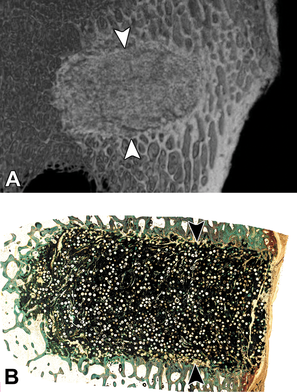
(A) Ex vivo microcomputed tomography of a bioresorbable porous scaffold implanted into the distal femur of a sheep; arrowheads demarcate the edges of the implantation site. (B) Histology slide correlating to Figure 1 demonstrating the healing response to the presence of the bioresorbable porous scaffold within the critical size defect in the sheep distal femoral condyle; arrowheads demarcate the edges of the implantation site, methyl methacrylate embedding with ground sectioning, Goldner’s trichrome stain.
Dental studies commonly utilize either a canine or porcine model, with typically bilateral extraction of several premolars and molars on the mandible, followed by osteotomy creation. The osteotomy sites are subsequently filled with a bone filler and covered with a dental membrane to promote guided tissue regeneration (GTR), which serves to inhibit the infiltration of fibrous connective tissue and to promote the entrance of growth factors and other cellular milieu that contribute to new bone formation (Sculean, Nikolidakis, and Schwarz 2008). Two common models are alveolar ridge restoration and lateral ridge augmentation. The main objective of alveolar ridge restoration is to restore the height of the alveolar ridge for bone implant placement (Jovanovic et al. 2007), while in lateral ridge augmentation, the lingual aspect of the alveolar ridge remains intact while the osteotomies occur on the buccal aspect of the alveolar ridge (Zubery et al. 2007). After the premolars and molars are extracted, it is recommended to allow the extraction sites to heal for 8 to 12 weeks prior to creation of the osteotomy/defect site and placement of bone filler within the osteotomy sites. When testing various bone fillers and/or GTR membranes, it is important to dedicate an appropriate number of sites to a sham group (Figure 2), which essentially has the same size defect created but no bone filler or membrane is placed; the amount of new bone growth can then be compared across all treatments to assess the amount of bone that would grow with and without treatment. When testing dental implants, these are typically either implanted directly into the healed tooth extraction sites (i.e., without an osteotomy defect created) or can be implanted 2 to 3 months after bone filler is placed within an osteotomy site (i.e., when the bone filler has been remodeled or integrated into the new alveolar bone formation) in order to have a solid base within the alveolar ridge into which to place the implant. Smeets et al. (2016) have recently published a review of various dental implant surface modifications and the impact of the modifications on osseointegration.
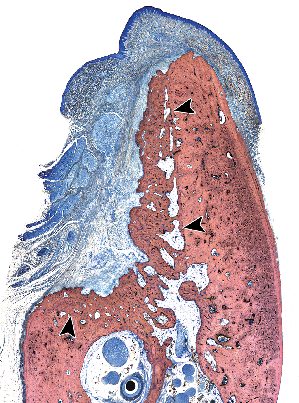
A mandibular defect lateral ridge augmentation model in the canine at 13 weeks after defect creation. This is a sham control site and is meant to demonstrate the amount of bone that would grow within a defect without the placement of a bone filler and/or a membrane for guided tissue regeneration; arrowheads demonstrate the edges of the defect; methyl methacrylate-embedded ground section, Stevenel’s blue stain.
The rabbit and sheep posterolateral lumbar intertransverse process spinal fusion (PLF) models are commonly used but are not always successful as bridging of bone across the transverse processes can be difficult to obtain, depending on the type and amount of bone filler that is used for the augmentation (Ghodasra et al. 2014; Kim et al. 2004; Wheeler et al. 2007). An ASTM standard has recently been published describing the rabbit lumbar intertransverse PLF model (ASTM F3207-17 2017). Other common procedures are interbody fusion (at cervical or lumbar intervertebral locations) or testing of artificial intervertebral discs; these studies are most commonly performed using the ovine model due to the similarity in size and healing response to humans (Lindley et al. 2017), though the nonhuman primate has been utilized in the past (McAfee et al. 2003).
Osteoinduction studies consist of the implantation of a biomaterial into nonbone tissue such as muscle or subcutaneous tissue, with subsequent evaluation for evidence of ectopic bone growth (osteoinduction) within the implantation areas. The dog, goat, baboon, rat, rabbit, and sheep models are commonly used for osteoinduction studies (Barradas et al. 2011).
The modeling of tendon repair surgeries can be challenging in animals due to the difference in anatomy between bipeds and quadrupeds. Rotator cuff tendon repair is a common procedure in the aging human population; because of this, innovative techniques and anchors are being developed to support the healing process and the combined system must undergo preclinical testing. Sheep are commonly used for rotator cuff tendon repair testing as the infraspinatus tendon of sheep is similar to the supraspinatus tendon anatomy in humans (Gerber et al. 1994). These can be difficult studies as the transection of the infraspinatus tendon can lead to excessive retraction of the tendon and it is not possible to prevent sheep from full weight-bearing after a reattachment surgery (Turner 2007). Achilles tendon repair can be done using biomaterial scaffolds or suture models in dogs, rats, or rabbits (Gilbert et al. 2007; Liao et al. 2011; Ouyang et al. 2003; Zantop et al. 2006). Several techniques for soft-tissue reconstruction of the anterior cruciate ligament (ACL) and interference screw fixation exist, most of which involve a bone tunnel with implanted interference screw retaining a bone-patellar tendon-bone graft within the distal femur and proximal tibia (Stratton-Powell et al. 2016; Weiler et al. 2002; Zantop et al. 2006).
Osteoarthritis is a complicated process, in which trauma to the cartilage and menisci as well as inflammation within the joint synovium contribute to degeneration of the cartilage and osteophyte formation, ultimately resulting in pain and chronic progression of the inflammatory cascade. During the degenerative process, cartilage fissures and defects can form that lead to instability of the joint, resulting in pain when the subchondral bone is affected (Kuyinu et al. 2016). Sheep serve as a very useful animal model to test osteochondral defect repair biomaterials (i.e., bone filler or scaffolds used to replace the damaged cartilage) due to the similarity in size between sheep and human femoral condyles (Kon et al. 2010). It is important to compare a novel test article to a sham-operated site, such as a surgical chondroplasty, in which a similar size defect is made in the femoral condyle and tissue is removed to the subchondral bone layer (Figure 3A and B); this will allow for comparison of healing for each treatment to the standard surgical treatment. End-stage osteoarthritis is frequently treated with a joint replacement, which can sometimes result in wear particle debris entering the joint fluid or synovium (Ingham and Fisher 2000; Purdue et al. 2006). Common models for wear particle debris include canine, rabbit, and rodent models (i.e., wear particle debris is injected or inserted into the hip, knee, or spinal joints; Evans et al. 1984; J. Patel et al. 2018).
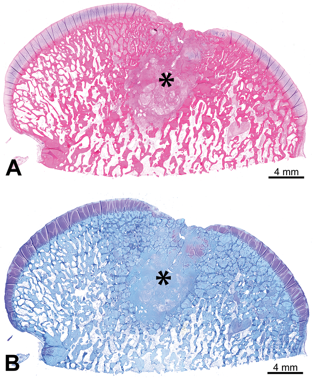
(A) and (B) Distal femoral condyle of a sheep with a 10-mm full-thickness chondroplasty control defect in the cartilage of the medial condyle at 3 months postsurgery, demonstrating the appearance with an hematoxylin and eosin stain (A) and toluidine blue stain (B); defect site is marked by an asterisk; decalcification with paraffin embedding.
Newer technology for bone and tissue regeneration such as utilizing gene therapy or mesenchymal stem cells to encourage growth of an intended tissue type (i.e., bone formation) within a defect is becoming more common (Lichte et al. 2011); this technology can be tested in calvarial defects (Koob et al. 2011) or in long bone defect models if load-bearing is necessary (Seebach et al. 2010).
Tissue Collection at Necropsy
At the time of necropsy, the bone containing the orthopedic implant (i.e., explanted orthopedic device or defect site) needs to be isolated in such a manner that the surrounding soft tissues (muscle, subcutaneous adipose tissue, and skin) are removed, leaving any relevant soft tissue overlying the defect site intact as well as at least 1 to 2 cm of bone surrounding the defect on all sides. Gross examination of the defect sites with a description of the shape and location of the implant (if visible) and a description of any notable local tissue reaction (redness, swelling, edema, etc.) are important parts of the necropsy and provide pertinent information about the performance of the orthopedic device. Digital imaging of the implantation sites prior to sample collection is recommended as the gross appearance of the defect sites may serve as a useful reference during the evaluation. Various scoring systems exist to macroscopically evaluate and semiquantitatively score the gross findings; these can either originate from published material or can be adapted or developed by the study pathologist to adequately evaluate each particular study. For example, in the case of an osteochondral implant (Cook et al. 2014; Husby et al. 2016), the implant can be evaluated macroscopically to determine the position of the implant with respect to the adjacent cartilage surface; additional features such as macroscopic appearance of the surface, integration with surrounding cartilage, color of the graft, etc., can be assessed as applicable (van den Borne et al. 2007).
Regardless of the type of orthopedic implant, it is necessary to ensure proper fixation of the bone samples at the time of necropsy. One of the most important steps for fixation is to be sure to fully transect at least one end of a long bone to allow for infiltration of 10% neutral-buffered formalin (NBF) into the marrow cavity. For example, with intramedullary pin implants, if at least one end of the long bone is not transected at necropsy, then fixation will likely be poor, resulting in autolysis and undesirable histology slides. Depending on the size of bone samples, fixation in NBF can take 7 days or longer, at which time the samples should be trimmed and assessed for full fixation prior to processing for histology (i.e., if the marrow cavity or surrounding connective tissue is pink or red instead of white or pale tan upon trimming, then the sample is not fully fixed and needs to remain in NBF until full fixation occurs).
For rabbit posterolateral spinal fusion studies, manual palpation is performed in a nondestructive manner in order to assess the efficacy of fusion of the intervertebral space. This is conducted at the time of necropsy, prior to fixation in formalin, and involves flexing the spine in the dorsal–ventral axis and in the medial–lateral axis to assess for various bending forces (ASTM F3207-17 2017). It is important to exercise caution during the manual palpation process to avoid dislodging the healing bone. Also, performing high-resolution radiography and/or microcomputed tomography (microCT) prior to manual palpation is important to rule-out artifacts caused by the manual palpation. This palpation technique can be helpful to use as evidence of bone healing, but the results need to be interpreted in accordance with the imaging and histopathology results.
For intervertebral spinal fusion cage studies in sheep, performing a full body perfusion with formalin can be extremely helpful to both decrease the time needed for fixation after the necropsy and to increase the uniformity and completeness of the fixation. This is especially helpful when the implantation sites contain additional internal fixation devices.
Due to a possible interaction of buffered formalin with some types of calcium phosphates (e.g., hydroxyapatite, tricalcium phosphate, or calcium sulfate), it is recommended by Bauer and Mahovlic (2016) to fix trimmed bone samples in 70% ethanol instead of using formalin when a calcium phosphate biomaterial is present (Kieswetter et al. 1994). Also, when bone samples have been labeled with fluorochromes, fixation in 70% ethanol has been reported to have successful results (Bauer and Mahovlic 2003). Additionally, refrigerating the bone samples and protecting them from light exposure are important to maintain a high level of fluorescence for subsequent fluorescence microscopy.
Imaging
High-resolution radiography (e.g., Faxitron) of the ex vivo tissue is very useful for determining the exact location of an orthopedic implant prior to trimming and may be helpful for evaluating the tissue response surrounding the implant. This imaging modality can be used to assess for pathologic fractures as well as for damage induced by manual palpation or handling/shipping of the sample. Additionally, it is essential to use high-resolution radiography when decalcifying bone samples to confirm full decalcification prior to paraffin processing and microtomy of the tissue.
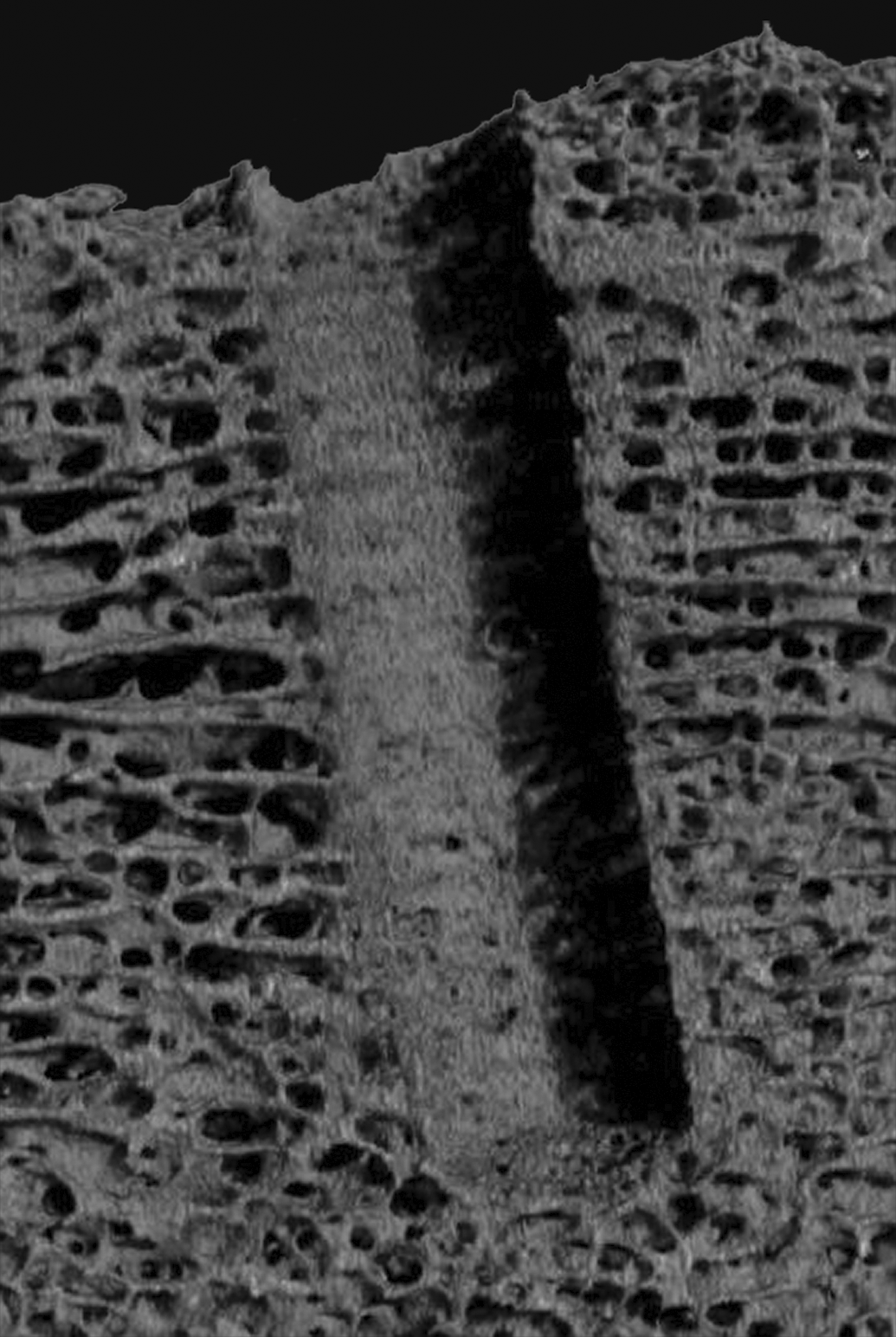
MicroCT is an excellent tool that is used both for localizing a defect site prior to trimming for histology (Figure 4) and for analyzing the implant site in 3 dimensions (3-D) to view and assess the healing response throughout the defect site. Resulting files can be presented as both 2-D images (Figures 5 and 6) and 3-D animation videos. In some cases, depending on the composition and density of the implant material with respect to its surrounding tissue, the microCT images can be analyzed to threshold the various tissue types. This allows for quantification of parameters such as bone growth within the region of interest (ROI), bone-implant surface contact, and bone marrow density quantification, as well as primary bone, implant, and soft tissue volume measurements (Kang et al. 2015). In the case of bioabsorbable implant studies, it is essential to utilize microCT at early and late time points in order to assess the biodegradation/bioabsorption response. MicroCT can be used to determine or confirm the location of a bioabsorbable implant at late time points by utilizing the bone density of the original implantation site compared to the surrounding preexisting bone after the implant is fully bioabsorbed (Cho et al. 2012; Figure 4).
Ex vivo microcomputed tomography (microCT) image of a rabbit femur implanted with three bioabsorbable polymer implants at the 13-week time point; the microCT demonstrates the implant sites due to the density differences of the implant compared to the surrounding intact bone and allows for accurate trimming of the implant sites for histology purposes.
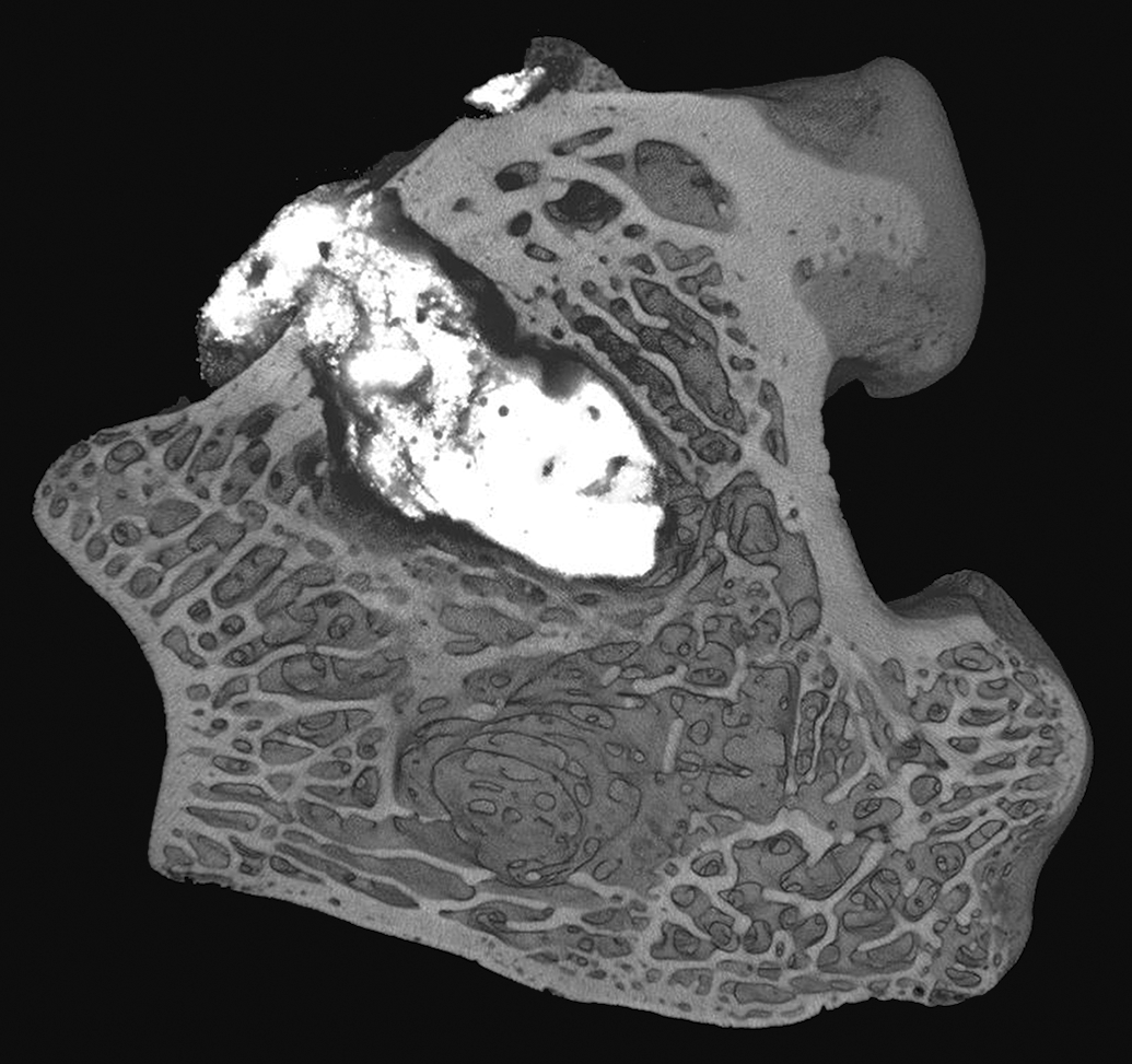
Ex vivo microcomputed tomography of the distal femoral epiphysis implanted with a radiolucent polyetheretherketone (PEEK) rod in a press-fit insertion bone defect model in sheep. Reprinted with modifications from Biomed Mater Res Part B, J. Khoury et al. (2017). Enhanced bioactivity and osseointegration of PEEK with accelerated neutral atom beam technology, 105B:531–543.
Ex vivo microcomputed tomography of a distal femur implanted with a glass ionomer cement in a bone defect model in rabbits. Reprinted with modifications from Materials Letters, C. M. Pierlot et al. (2016). A pilot evaluation of an aluminum free glass ionomer cement using a sub-chronic osseous defect model in New Zealand white rabbits, 184:301–304.
Mechanical Testing
A common type of mechanical testing for orthopedic studies is manual palpation; this can be conducted in posterolateral fusion studies with bone graft implantation in rabbits per the ASTM guidance (ASTM F3207-17 2017) or with intervertebral ovine models for interbody spinal fusion cage testing. Essentially, the vertebral column is palpated in a flexion-extension, lateral bending, and/or axial torsion direction. Alternatively, universal or multiaxial mechanical testing equipment is used, and pure moments are applied to the segment to evaluate the rigidity of the fixation (i.e., the range of motion exhibited by the spinal segments adjacent to and at the fixation site; McGilvray et al. 2018). Although this is believed to be nondestructive, care must be taken to avoid introducing artifactual microscopic changes that could be misinterpreted as treatment related by the pathologist following the mechanical testing. It is recommended to perform high-resolution radiography and microCT imaging prior to the mechanical testing, and in some cases, these imaging modalities may need to be repeated after the range-of-motion testing is completed.
Universal material testing equipment can be used to evaluate mechanical performance on specifically designated explanted samples. Static axial microindentation is a commonly used mechanical test that is performed on fresh specimens immediately after necropsy; the tissues can either be tested at room temperature or immersed in a semiphysiological solution at 37°C. For this test, various probe sizes with a smaller diameter than that of the defect or implanted ROI can be used for the microindentation procedure, and the ultimate goal is to determine the strength of the healing response without damaging the tissues or altering the histology and histomorphometry results (Hutchens et al. 2016).
For samples that are dedicated to mechanical testing (and thus will not have further histopathology or histomorphometry performed), several destructive mechanical tests exist to determine the strength of the repair. For example, for press-fit insertions, either pushout or pullout testing can be done using appropriate jigs (Babiker et al. 2012; Bobyn et al. 1999; Nishiguchi et al. 2001). For osseointegrated screws, torque-out and torsion testing can be performed via either digital torque measurement or using universal testing equipment. The osseointegrated implant is tested for stiffness and strength until failure occurs. Uniaxial tension tests can also be performed, for example, on spinal specimens with each end of the spinal sample held in place by potting in PMMA (Yamada et al. 2015). Typical measurements include the modulus of elasticity, yield strength, and ultimate strength, which can be calculated from the stress–strain curves. These results can be corroborated with the histomorphometry results for bone-implant contact (BIC) that are performed on separate samples that are dedicated for histopathological analysis.
Histology Techniques and Digital Imaging
After proper fixation has been confirmed, and after microCT and/or high-resolution radiography has been performed, the next step in preparation of histology slides is trimming of the defect sites. The methods for trimming vary depending on the ultimate goal of the histology and the embedding media used (i.e., either decalcification of the bone tissue with paraffin embedding or, alternatively, embedding in plastic resin without decalcification). Also, trimming varies significantly from study to study as it depends on the type of implant, the shape of the implant (rod, plate, screw, bone substitute, etc.), and the physical properties of the implant (solid, porous, coated, smooth vs. rough surface, etc.). If one of the goals of the histopathology and/or histomorphometry evaluation is to assess the osseointegration (BIC), then a longitudinal section through the implant is usually best as it typically maximizes the implant surface area as opposed to a cross section. Alternatively, multiple cross sections of the implant can be made depending on the structure of the implant, but this is usually less ideal as only focal areas of the implant are being evaluated compared to the entire length of the implant in the case of longitudinal sections.
Decalcification with paraffin embedding will work well only if the implant can be sectioned easily in paraffin (this may be the case for bone fillers, some bioresorbable implants, collagen-based implants, and some soft polymers), and if the decalcification process will not affect the implant. If there is any question as to whether an implant can withstand the decalcification process, then reagent testing should be performed ahead of time to test the implant in various types of decalcification solutions (i.e., formical, immunocal, ethylenediaminetetraacetic acid [EDTA]). If an implant is suitable for decalcification, then the goal is to trim the bone sample to isolate the defect with up to 1 cm of intact bone on all sides. The sample is placed into an appropriate decalcification solution that is selected based upon the intended rate and type of decalcification. Formical tends to decalcify quickly and is commonly used as a general purpose decalcification agent for most bone studies, while immunocal decalcifies at a slightly slower rate but has the benefit of retaining antigen binding sites if immunolabeling is intended for the samples. Alternatively, EDTA tends to be a very slow decalcifying agent, is less harsh than formical or immunocal, and is used for friable implants. The sample is serially radiographed using high-resolution imaging at daily or weekly intervals (depending on the size of the sample and the type of decalcification agent, as both variables will affect how quickly the decalcification process occurs). Once decalcification is confirmed via absence of densely radiopaque areas within the central aspect of the bone on the radiographs, the samples are then trimmed in a plane that will isolate the center of the defect. For example, if the defect is located in the medial condyle of the femur, a sagittal plane of sectioning through the center of the defect will provide histology that demonstrates the full sagittal section of the defect, with surrounding anterior and posterior aspects of the medial condyle. Alternatively, a coronal plane can be made that would demonstrate the medial and lateral femoral condyles. Thus, the plane of sectioning depends on the goals for the histopathological evaluation and needs to be determined prior to trimming with the assistance of the study pathologist. Upon trimming, typically one half of the defect site is submitted for paraffin embedding while the other half is retained in formalin, and the submitted tissue undergoes processing to dehydrate the tissue and infiltrate with paraffin, followed by embedding in paraffin. The tissue is then sectioned using a microtome at ∼5 to 8 µm thickness to produce histology slides that can then be stained with bone stains or immunohistochemical (IHC) markers.
The second, and arguably more common, route for processing for orthopedic studies is plastic embedding, which can include processing and embedding in methyl methacrylate (MMA), technovit (7200 or 9100), glycol methacrylate, or Spurr resin (Epon). To determine which embedding medium is best for a study, reagent testing can be performed prior to the study to ensure that the resin itself will not alter (e.g., dissolve) the implant material, resulting in loss of the implant integrity within the defect site. The most common embedding medium for bone studies in the authors’ experience is MMA as this allows for superb quality histology slides with several useful histology stains. For plastic embedding, it is important to trim the sample so that the defect or implant is surrounded by 1 to 2 cm of bone on both sides of the defect or implant site. Radiography of the samples prior to trimming is again important to allow for proper localization of the implant site; once the samples are trimmed, the implant site location or intended plane of sectioning can then be marked on the outside of the bone sample (e.g., on the cortex for long bone defects) using tissue dye. To do this, the sample should be blotted dry, the tissue dye is marked onto the sample using an applicator stick, and then either 100% ethanol or 10% acetic acid can be applied to the marked area using a cotton swab to “fix” the dye in place, so that it does not disintegrate when the sample is placed back into formalin prior to processing. After marking the plane of sectioning, the samples can be processed to dehydrate the samples and then infiltrated and embedded with MMA (or other appropriate medium). Once the plastic has hardened, the samples can be sectioned into wafers using a diamond saw, and the wafers are typically ground to a thickness ranging between 30 and 100 µm to produce ground sections. For bone studies that contain a histomorphometry end point, it is most ideal to use ground sections as very few artifacts (e.g., tissue tears/folding or artifactually induced white space between tissue types) are typically present. Occasionally, thin sections are requested for small bones (such as those of rodents), which involves microtoming at typically 5 to 10 µm; however, thin sections are technically challenging to produce and may contain folding, tearing, or other artifacts that can interfere with histomorphometry end points. The histology slides can then be stained with a variety of stains, depending on the intended histological evaluation.
The goal of staining histology slides for orthopedic studies is to visualize both the inflammatory reaction and other healing responses within the defect (i.e., the “safety” assessment utilizing the classic hematoxylin and eosin [H&E] stain for histology) as well as describing and evaluating the new bone formation (i.e., the “efficacy” assessment utilizing special stains such as Stevenel’s blue or Goldner’s trichrome). The typical H&E stain is necessary for every study as it permits the full evaluation of the inflammatory response to determine biocompatibility, but it does not allow for obvious determination of new bone versus preexisting bone within the defect site (all bone stains a purple-pink color, and thus, the transition from preexisting bone to new bone growth is not always easily discernable with H&E staining). Thus, a second stain intended for determination of the new bone formation within the defect site, and sometimes delineating osteoid versus mineralized bone, can be very helpful for the histopathological evaluation. Additional special stains or IHC reactions are necessary in some studies to fully evaluate a targeted marker or response.
For decalcification and paraffin embedding, commonly used histology stains are H&E, Masson’s trichrome, Safranin O-fast green, and Toluidine blue. Masson’s trichrome demonstrates differentiation between osteoid (orange-red or red) and mineralized bone (blue; Asonova and Migalkin 1996). Safranin O-fast green and Toluidine blue are useful for cartilage as they stain the glycosaminoglycans and proteoglycans a different shade of red-orange (Safranin O-fast green) or dark blue (Toluidine blue) compared to the areas of cartilage lacking these components (blue for Safranin O-fast green or light blue for Toluidine blue; Gerwin et al. 2010). Additionally, for histomorphometric quantification of bone trabecular thicknesses, Toluidine blue is an effective stain to use as all mineralized bone will be dark blue and is thus readily visible (Chow, Tobias, and Chambers 1992). Paraffin-embedded histology permits the use of other special stains, such as TUNEL (Terminal deoxynucleotidyl transferase mediate dUTP nick end labeling) for assessing apoptosis (Mangiavini and Schipani 2014), TRAP (tartrate resistant acid phosphatase) for labeling osteoclasts (Kollet et al. 2006), and Von Kossa for highlighting mineralized bone (Witte et al. 2007). Additionally, IHC markers can be used on both plastic and paraffin-embedded slides, though performing IHC on plastic-embedded sections can be more technically challenging and is not always successful. For example, IHC markers such as alkaline phosphatase, type I collagen, osteonectin, osteopontin, osteocalcin, and bone sialoprotein can be utilized in specially processed, resin-embedded ground sections of bone (Knabe et al. 2006).
A relatively large number of special stains can be performed with MMA, and to some extent with other plastic resins. Namely, H&E, Stevenel’s blue, Goldner’s trichrome, methylene blue-basic fuchsin, Paragon (Toluidine blue-basic fuchsin), Sanderson’s rapid bone stain, Macneal’s tetrachrome, Verhoeff-van Giesson, and TRAP staining for osteoclasts. Stevenel’s blue with van Gieson’s picrofuchsin as a counterstain (Maniatopoulos et al. 1986) is frequently used as a bone stain as it helps to differentiate new bone growth from preexisting bone. Preexisting lamellar bone is typically light brown-tan with osteon formation while newer bone growth is dark brown with osteocytes within lacunae that are closer together without osteon formation. This stain does show osteoid as dark indigo blue surrounding the calcified bone, but it can be difficult to discern osteoid versus the intervening soft tissues, which stain light blue. Most bone studies can be evaluated by using H&E and Stevenel’s blue stains. For histomorphometric quantification of osteoid, methylene blue-basic fuchsin, Sanderson’s rapid bone stain (with either an acid fuchsin counterstain or van Gieson counterstain), Verhoeff-van Giesson (in this case, bone stains black while osteoid stains pink), Goldner’s trichrome, and Von Kossa with an H&E counter stain (Lewiecki et al. 2017) will stain osteoid separately from mineralized bone. Goldner’s trichrome has been found in the authors’ experience to stain variably on ground sections (calcified bone should stain green, and osteoid should stain orange, but the center of the bone trabeculae will often stain variably orange-green on ground sections), with improved staining consistency on thin sections. When staining cartilage on ground MMA sections, Safranin O has exhibited poor results in the authors’ experience, and thus, the usual stain of choice is Toluidine blue; even so, the staining of glycosaminoglycans and proteoglycans can be somewhat variable.
Histopathology Evaluation
A major end point of many orthopedic studies is to evaluate the biocompatibility of the implant with the surrounding tissue utilizing the ISO 10993 Part 6 guidance document (ISO 10993-6 2016). This standard is also known for its appended histopathology scoring system. A modified version (Tables 1 –3) of this scoring system, with modifications created by manuscript author N. Jackson, is commonly used by the author in successful regulatory submissions for orthopedic implant studies. These modifications are most useful for long bone unicortical defect studies with biostable implants, although this scoring system can be used for bioabsorbable implants during the early time points prior to the active phase of bioabsorption (Figure 7A–D). Essentially, the ISO guidance document is followed with the addition of parameters such as osseointegration, which can be evaluated as cortical apposition separately from medullary apposition, and capsular thickness, which involves measuring the thickness of the fibrous or fibrovascular tissue surrounding the implant at typically three peripheral locations using an ocular micrometer. An irritancy/reactivity score is then calculated to determine the irritancy status of the test implant relative to the control implant; this is completed in accordance with the ISO 10993-6 guidance document. During this evaluation, the H&E stain is imperative to definitively determine the inflammatory cell types, and the bone-specific stain (such as Stevenel’s blue) is used to determine the bone quality at the interface. An additional parameter, amount of new bone growth, can be semiquantified as well depending on the study objectives.
Modified ISO 10993:6 Data Table for Evaluating Osseointgration, Healing Response, and Biocompatibility Response for Biostable Orthopedic Implants Located within a Long Bone Unicortical or Bicortical Defect.
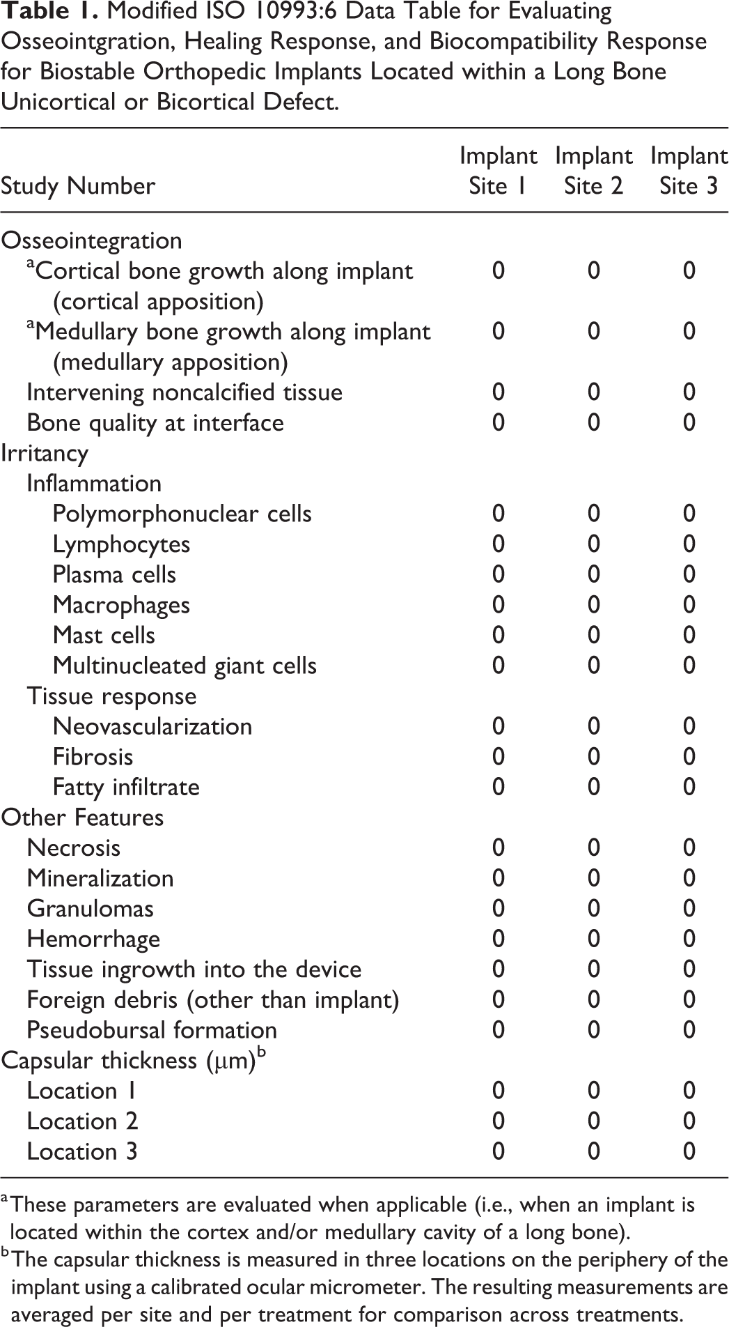
a These parameters are evaluated when applicable (i.e., when an implant is located within the cortex and/or medullary cavity of a long bone).
b The capsular thickness is measured in three locations on the periphery of the implant using a calibrated ocular micrometer. The resulting measurements are averaged per site and per treatment for comparison across treatments.
Scoring Parameters (with Slight Modifications Based on ISO 10993:6 [2016]).
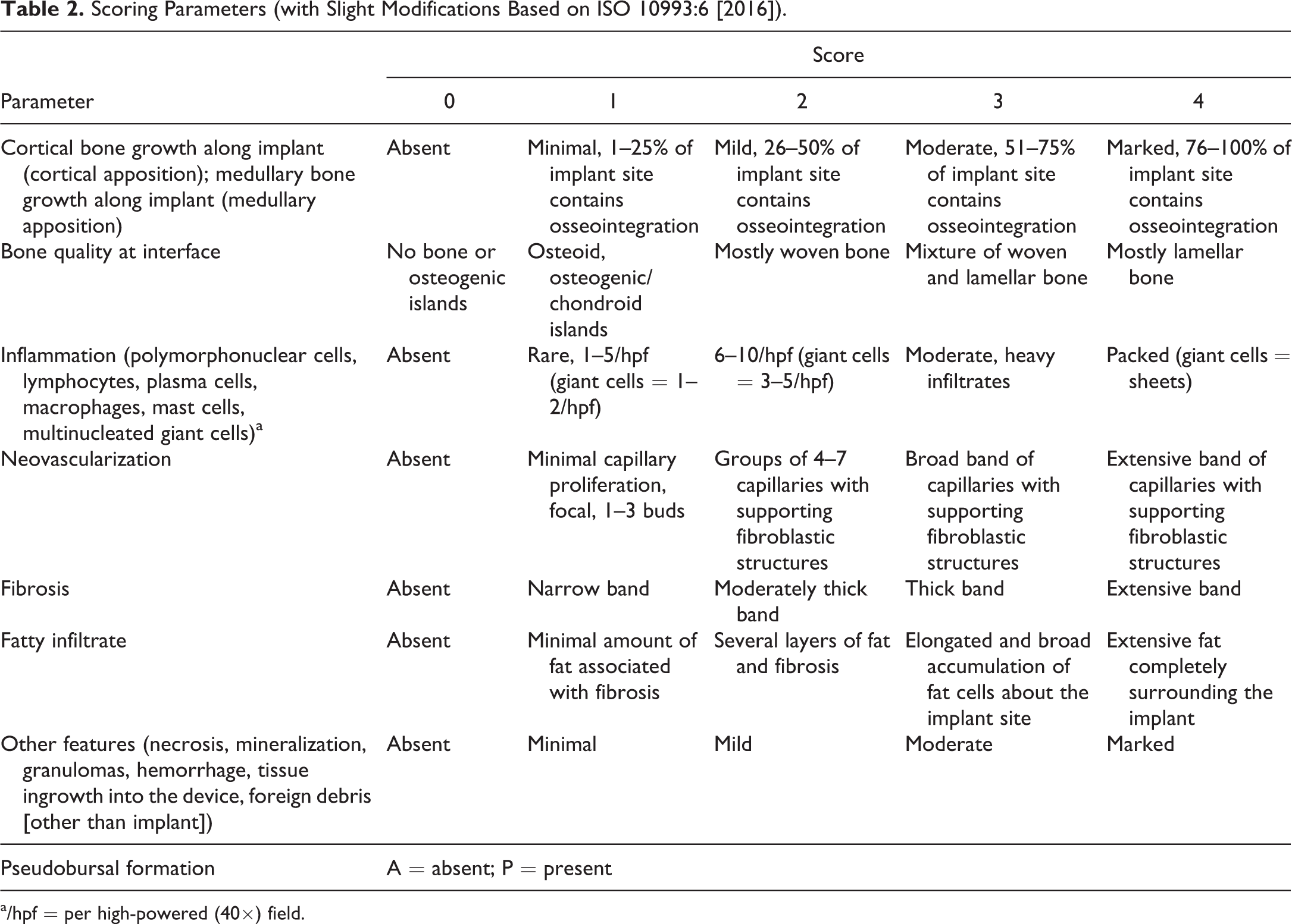
a/hpf = per high-powered (40×) field.
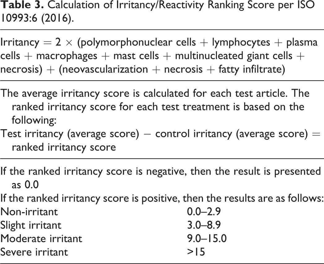
Calculation of Irritancy/Reactivity Ranking Score per ISO 10993:6 (2016).
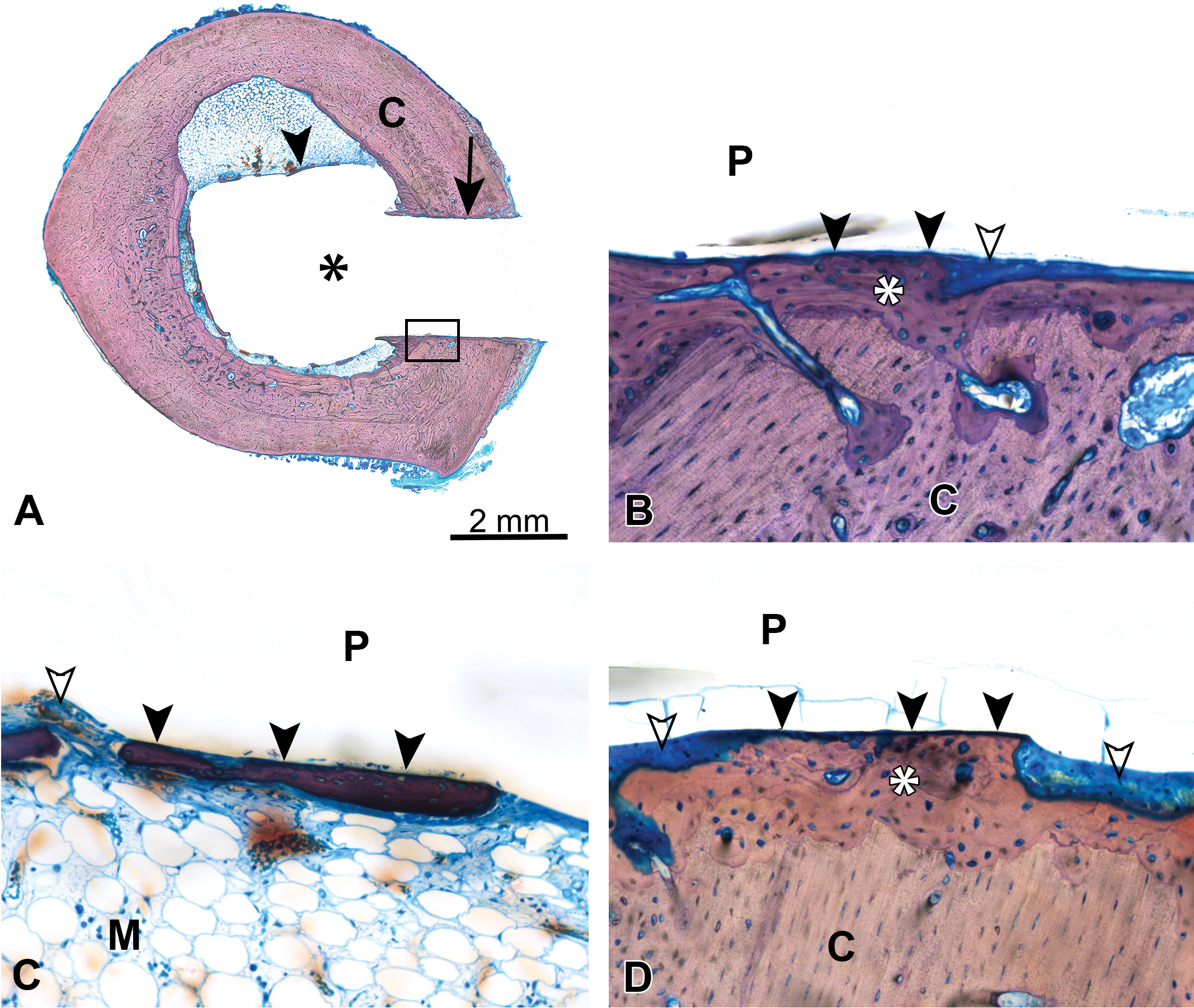
(A) Unicortical defect in a rabbit femur implant model at 4 weeks demonstrating a bioabsorbable polymer implant (asterisk) with apposition of cortical (C) bone (arrow) and few areas of apposition of medullary bone (arrowhead), box demonstrates location of image for (B); methyl methacrylate (MMA)-embedded ground section, Stevenel’s blue stain. (B) Same unicortical defect as (A) (rabbit femur model), demonstrating a bioabsorbable polymer implant (P) with preexisting cortical bone (C), new cortical bone growth (asterisk) with cortical apposition (closed arrowheads), and an area containing intervening soft tissue (open arrowhead); MMA-embedded ground section, Stevenel’s blue stain, original objective 20×, 4-week time point. (C) Similar unicortical defect as (A) (different site) at 4 weeks, demonstrating a bioabsorbable polymer implant (P) with apposition of new bone growth (closed arrowheads) within the medullary cavity (M) and areas containing intervening soft tissue (open arrowhead); MMA-embedded ground section, Stevenel’s blue stain, original objective 20×. (D) A unicortical defect in the rabbit femur model at 26 weeks demonstrating the same bioabsorbable polymer implant material (P) as presented in (A)–(C) with preexisting cortical bone (C), new cortical bone growth (asterisk) with cortical apposition (closed arrowheads), and areas containing intervening soft tissue and inflammatory cells (open arrowheads); MMA-embedded ground section, Stevenel’s blue stain, original objective 20×.
Osseointegration is usually the most important response for a biostable orthopedic implant as BIC is what will provide for long-term stability of the implant within the surrounding bone (Figure 8A and B). In contrast, for bioabsorbable implants, it is important to assess the biodegradation and bioabsorption response. Typically, the implant must first start to degrade by hydrolysis, resulting in a decrease in molecular weight, and eventually the implant will lose strength and subsequently break down into particulates and/or secondary products that are absorbed by the body and can be excreted (e.g., in the form of glycolic acid, glycoxylate, or lactic acid; Amini, Wallace, and Nukavarapu 2011; Athanasiou et al. 1998; Maurus and Kaeding 2004; Vert, Mauduit, and Li 1994). This process can appear histologically as surface fragmentation of the implant due to hydrolysis, or as a loss in width of the implant with peripheral phagocytic activity by macrophages and multinucleated giant cells that engulf the bioabsorbable material to remove the material from the site. Depending on the properties of the implant material, evaluating with polarized light may assist in determining the amount of material remaining (if the material is a bioabsorbable polymer, for instance). Also, assessing any tissue ingrowth (connective tissue or bone) into the bioabsorbable implant may be helpful to characterize and track the bioabsorption response over time.
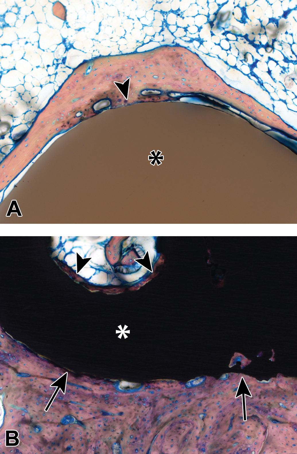
(A) A polyetheretherketone (PEEK) plug within the distal femoral condyle of a rabbit at 84 days post-implantation, demonstrating the PEEK implant (asterisk) and new bone growth that is apposed to the implant surface in this area (arrowhead); methyl methacrylate (MMA)-embedded ground section, Stevenel’s blue stain, original objective 10×. Copyright© 2018 K2M. All rights reserved. Used with the permission of K2M. (B) A porous titanium plug within the distal femoral condyle of a rabbit at 84 days post-implantation, demonstrating the titanium implant (asterisk) and new bone growth that is apposed to the implant surface (arrows) as well as within the pores of the implant (arrowheads); MMA-embedded ground section, Stevenel’s blue stain, original objective 10×. Copyright© 2018 K2M. All rights reserved. Used with the permission of K2M.
For bioabsorbable implants, osseointegration may be important at early time points but becomes less important over time as the goal of the bioabsorption response is to remove the bioresorbable material and to fill the area with tissue ingrowth. This process may take years, and thus, long-term studies may be necessary to fully investigate the bioresorption and bioabsorption processes if this information is needed for approval by regulatory agencies. A possible risk of bioabsorbable implants is having a biostable implant for 4 to 5 years that suddenly undergoes a “burst” effect, whereby the material abruptly degrades and incites a robust inflammatory response leading to osteolysis at the site and a draining tract, resulting in a late-term surgical procedure to remove the residual bioresorbable implant from the site (Amini, Wallace, and Nukavarapu 2011).
Several published evaluation techniques with histologic grading scales exist for fracture study evaluation (Allen, Wase, and Bear 1980; Inan et al. 2014). These studies can be technically challenging to evaluate due to inconsistency from interanimal variation in the healing response to the fracture, as well as lack of a “one-size-fits-all” scoring system to accurately describe the amounts of cartilage, fibrous tissue, and bone bridging within the fracture site. If necessary, the established grading scales for fracture site evaluation may be customized by the study pathologist to the particular animal model in order to obtain relevant data from the analysis.
Several prominent scoring systems have been published for osteoarthritis evaluations, with the Mankin score (Mankin et al. 1971) preceding the very popular OARSI (Osteoarthritis Research Society International) initiative (Pritzker et al. 2006). These scoring systems have been standardized for the most commonly used animal species in an effort to permit comparison of data across studies and animal models (Aigner et al. 2010; Gerwin et al. 2010; Glasson et al. 2010; Kraus et al. 2010; Laverty et al. 2010; Little et al. 2010; Mainil-Varlet et al. 2010).
Dental studies can be evaluated by using the ISO 10993 Part 6 recommendations with the addition of pertinent parameters such as degree of implant degradation, osseointegration, and/or alveolar ridge restoration.
Osteoinduction studies are commonly evaluated using the ASTM F2529-13 standard (ASTM F2529-13 2015), in which a demineralized bone product is implanted into skeletal muscle and analyzed at various time points to determine the amount of new bone growth. Other animal models and scoring systems exist for in vivo semiquantification of osteoinduction as well (Glowacki 2005; Han, Tang, and Nimni 2003).
Histomorphometry
Histomorphometry is an extremely helpful and valuable tool that is used in conjunction with the histopathological evaluation to assess the healing response for implanted biomaterials in orthopedic applications. Essentially, histomorphometry can be divided into static versus dynamic morphometry techniques. For both techniques, the first step is to use an appropriate slide scanning system to image the entire ROI. The captured image is then utilized for morphometry analysis techniques with an image analysis program such as ImagePro.
Static Morphometry
Arguably, the most important parameter to analyze for biostable implants is BIC. This is measured by tracing the edge of a solid implant to obtain the entire perimeter and additionally tracing areas that demonstrate osseointegration (BIC) with the implant surface (Figure 9); the result is presented as a percentage (%BIC = length of BIC/total perimeter length of implant).
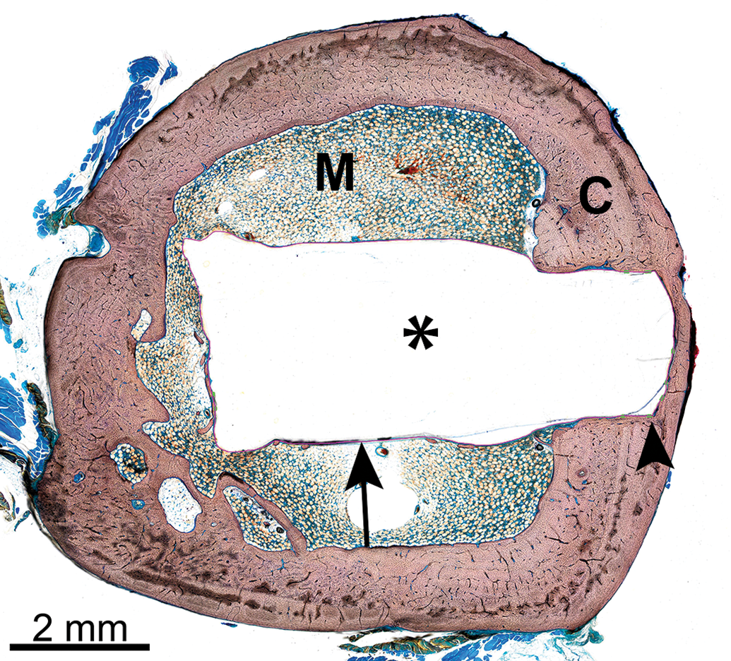
Representative histomorphometry masking of an implant site that is represented in the microcomputed tomography image of Figure 4, demonstrating the bioabsorbable polymer implant (asterisk; same implant material as Figures 7A–D), cortical bone (C), medullary cavity (M), and maskings showing areas of bone-implant contact (BIC, green lines, arrowhead) and areas lacking BIC (pink line, arrow). Methyl methacrylate (MMA)-embedded ground section, Stevenel’s blue stain.
Within the ROI, several parameters can often be color segmented to determine the proportion of the ROI that contains each tissue type. For example, new bone formation within the ROI and fibrous connective tissue within the ROI can often be segmented. Depending on the type and histological appearance of the implant material, the amount of implant remaining within the defect site can sometimes be determined via color segmentation (Figures 10 and 11). However, in some instances (such as with demineralized bone filler material), the implant biomaterial stains very similarly to bone and color segmentation will not differentiate the bone growth from the implant material; in these instances, the implant material will likely have to be hand-traced to differentiate it from bone, a process that is very labor-intensive and requires many hours to complete. Trying different bone stains may help to differentiate these findings, but typically the implant will stain similarly to bone, and thus, the implant will be visible to the human eye but will not be perceptible by the computer program (Figures 12A and B and 13).
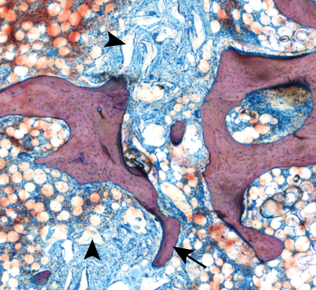
Histology slide from a median sternotomy fracture model in the ovine model with implantation of a bone hemostasis material (arrowheads), with new bone growth extending partially across the defect site (arrow); methyl methacrylate-embedded ground section, Stevenel’s blue stain, original objective 4×.
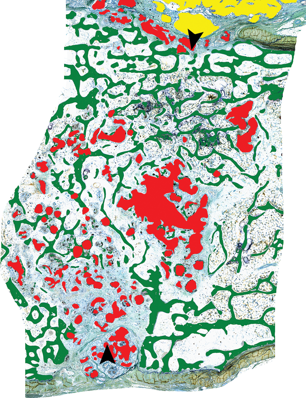
Histomorphometry masking of a median sternotomy fracture site in the sheep model demonstrating new bone growth that partially crosses the fracture plane (green), residual bone hemostasis material within the fracture site (red), and residual bone hemostasis material on the surface of the sternum (yellow); arrowheads denote the fracture edges. Methyl Methacrylate-embedded ground section, Stevenel’s blue stain.
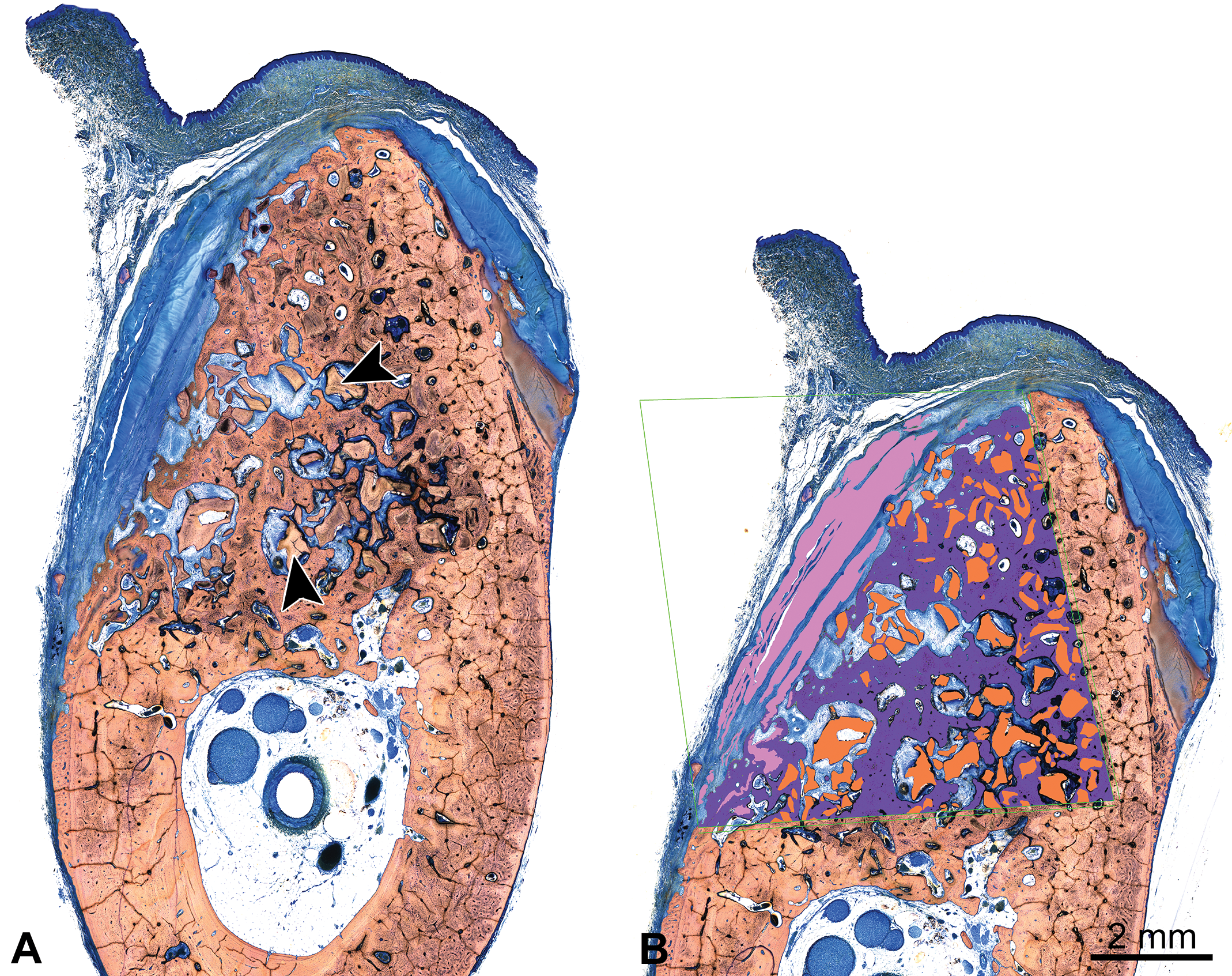
(A) Cross section of a canine mandibular defect implanted with a bone filler material (arrowheads) and covered with a collagen-based membrane for guided tissue regeneration, 24 weeks after implantation; methyl methacrylate (MMA)-embedded ground section, Stevenel’s blue stain. (B) Histomorphometry masking of the canine mandibular defect site implanted with a bone filler material (A), demonstrating new bone formation within the region of interest (purple), residual implant material (orange), and residual collagen membrane (pink); MMA-embedded ground section, Stevenel’s blue stain.
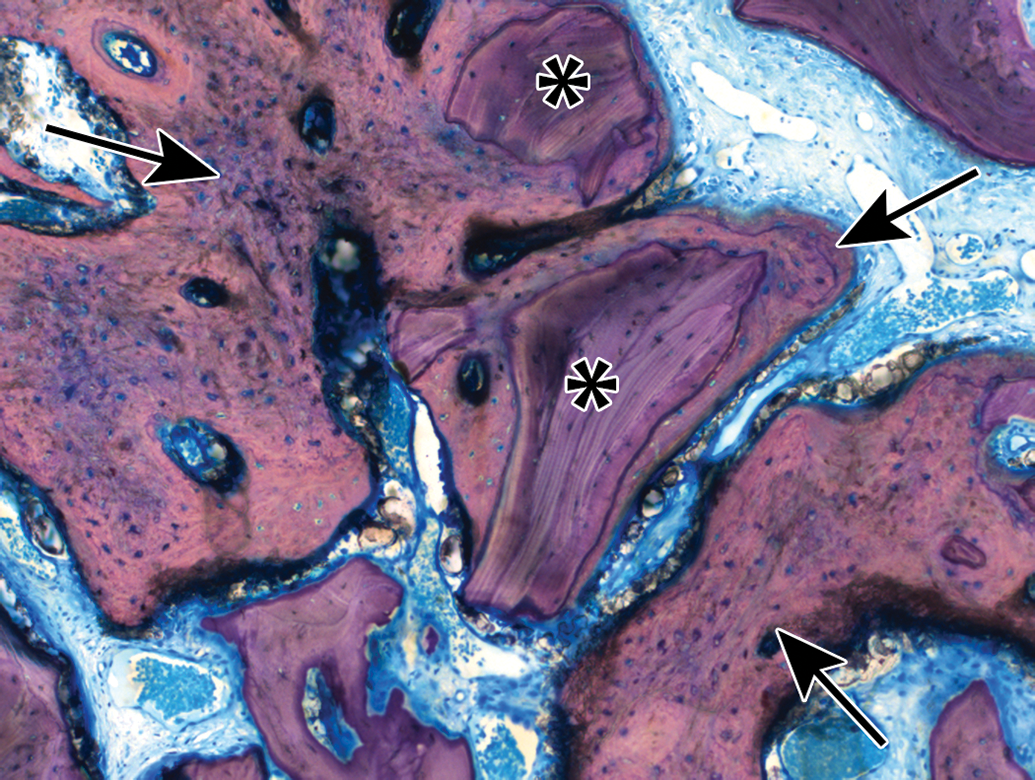
Histology slide from a mandibular defect model in a canine at 12-weeks post-implantation demonstrating new bone growth (arrows) surrounding particles of bone filler (asterisks), methyl methacrylate-embedded ground section, Stevenel’s blue stain, original objective 10×. The bone filler had to be hand-traced for histomorphometry as color segmentation was not possible due to the similar appearance of the bone filler and new bone.
Occasionally, an end point of an orthopedic device study will be to measure the amount of osteoid present within the defect site. This typically requires a different osteoid-specific stain such as Verhoeff-van Giesson, in which the bone appears black and osteoid appears pink, though Stevenel’s blue or Sanderson’s rapid bone stain may be effective in demonstrating the osteoid; the difficult part is differentiating osteoid from the medullary tissues, which stain similarly in color. When osteoid is measured morphometrically, it is typically presented as a percentage of the ROI.
Other parameters such as bone marrow, void space, and/or amount of fibrous tissue can be measured or calculated by subtracting the new bone growth and implant area from the total ROI.
Due to the variability in potentially measured parameters as well as morphology of each bone section itself, the lack of objectivity in bone quantification needs to be considered. Variability in sectioning, staining, and methodology can result in different quantitative outcomes, so consistency in the aforementioned parameters is essential for reliable study outcomes (Revell 1983).
Dynamic Morphometry
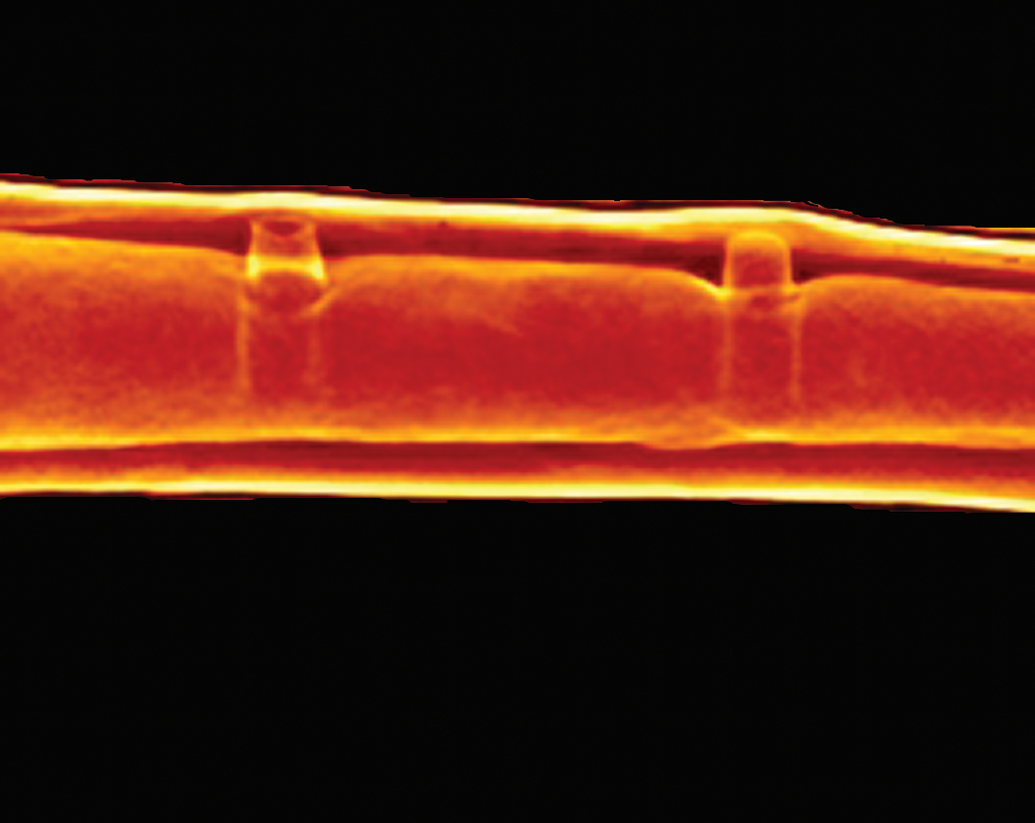
Dynamic morphometry is very useful for demonstrating the rate of new bone mineralization/bone growth and is occasionally used in orthopedic medical device studies. During the in-life phase of the study, the animal is treated with various fluorochrome labels (calcein green, alizarin red, xylenol orange, tetracycline, or calcein blue; Pautke et al. 2010; Sun et al. 1992) via either intraperitoneal, subcutaneous, or intravascular injection at predetermined intervals (e.g., at implantation, 2 weeks after implantation, and 4 weeks after implantation just prior to scheduled euthanasia). The tissues are harvested, fixed in 10% NBF or 70% ethanol, and typically ground MMA sections are made. Prior to staining the sections, the slides are scanned with an immunofluorescence scanner and the resulting images are then used for dynamic morphometry measurements. After the scans and analyses are confirmed to be acceptable, the unstained slides can then be stained and analyzed for the histopathology and static histomorphometry analyses.
Dynamic histomorphometry utilizes measurements of the distances between each fluorochrome label, called marker intervals, to determine the direction and rate of bone deposition, which is referred to as the mineral apposition rate (Hyun Hong et al. 2012; van Gaalen et al. 2010). Bone mineralization rates and the route of administration of the fluorochrome affect the resulting bandwidths, so care needs to be taken in consideration of dosing concentrations, timing, and histological sectioning thickness to optimize the visualization of fluorochrome labeling within the scanned images. While one label can be enough to determine the rate of bone deposition (Figure 14A), two labels administered at two different time points allow for more accurate measurements of bone deposition rates (Figure 14B).
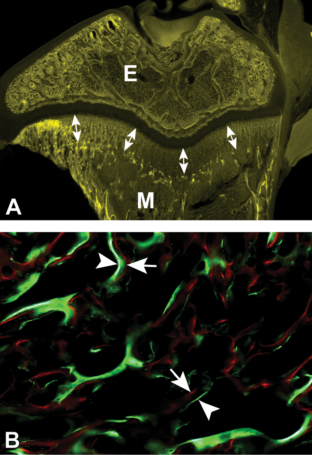
(A) Single-label dynamic histomorphometry of a rat tibia several weeks after a single dose of oxytetracycline was administered; the epiphysis (E) and metaphysis (M) are visible via fluorescence imaging with double headed arrows demonstrating the distance of bone growth along the metaphysis during this time from the initial bright band to the epiphyseal plate. (B) Dual-label dynamic histomorphometry of a canine femur with a 7-day interval between the administration of calcein green (arrowheads) and alizarin red (arrows); the distance between the red and green lines on the fluorescence image demonstrates the rate of bone growth over the 7-day period.
Conclusion
The orthopedic medical device field has undergone great expansion in recent years in both the types of medical devices that are being tested as well as the diverse array of materials being used for these devices. There is a great need for qualified pathologists to evaluate orthopedic implant studies, and these can be quite complex with many nuances that must be understood. Numerous animal models exist for testing various devices, and it is important to have input from a pathologist early in the study design process in order to have foresight to capture the proper study-specific end goals. Histopathology requires proper fixation of tissues after necropsy, and trimming must be completed by a skilled technician or pathologist with care taken to isolate the defect site properly. Histologic slide generation is very technically challenging and is a crucial step to provide high-quality slides for analysis. For novel device materials, reagent testing prior to histologic slide generation is frequently necessary in order to avoid complications such as losing the device due to degradation from the reagents used in the histologic processing. The histopathology evaluation needs to be uniquely targeted for each study in order to assess the proper end points and to determine any evidence of safety concerns. And finally, histomorphometry evaluation is an essential component of the analysis and provides necessary quantitative information that is used in the interpretation of the healing response to the orthopedic device. Thus, it is very important to have a skilled pathologist and technical team when pursuing orthopedic implant testing.
Footnotes
Acknowledgments
The authors would like to express appreciation and gratitude to the histology laboratories at both Alizée Pathology and AccelLAB for creating high-quality histology slides and images and Fabian Soza at AccelLAB for creating the microCT images contained within this article.
Author Contributions
Authors (NJ, MA, MC) contributed to conception or design; data acquisition, analysis, or interpretation (NJ, DV, MA, JS, MC); drafting the manuscript (NJ); and critically revising the manuscript (NJ, DV, MA, JS, MC). All authors gave final approval and agreed to be accountable for all aspects of work in ensuring that questions relating to the accuracy or integrity of any part of the work are appropriately investigated and resolved.
Declaration of Conflicting Interests
The author(s) declared no potential, real, or perceived conflicts of interest with respect to the research, authorship, and/or publication of this article.
Funding
The author(s) received no financial support for the research, authorship, and/or publication of this article.