
Abstract
Ensuring roadway stability is fundamental to coal mine safety, with the retention of a reasonable coal pillar width being a key factor in maintaining roadway integrity. This study establishes a mechanical model of roof structure and coal pillar load-bearing based on engineering practice, and derives a theoretical formula for stress distribution varying with coal pillar width. Research indicates that the vertical stress distribution in the coal pillar transitions from a single-peak to a double-peak pattern as the width increases. Coal pillars without an elastic core exhibit limited bearing capacity at smaller widths, with stress peaks and plastic zone ranges expanding as the width increases. In contrast, coal pillars with an elastic core demonstrate significantly enhanced bearing capacity, where the elastic core range expands markedly with increasing width, and the stress peak stabilizes. Based on the stress characteristics of elastic-core coal pillars, a corresponding loading–unloading constitutive model was further developed. Based on this model, an energy-based rock burst hazard index K was proposed, where K < 1 indicates the pillar is in a stable state with no risk of rock burst. Ultimately, a method for determining the optimal width of coal pillars was established.
Introduction
Rock burst represents a significant dynamic disaster in coal mining, with safety assessments primarily concentrating on roadway stability (Pan et al., 2023). Gob-side entry driving is a tunneling layout method specifically designed to optimize the surrounding rock stress structure and minimize the loss of coal pillars (Hua et al., 2011). This approach has been widely implemented in mining operations. A critical prerequisite for the successful implementation of gob-side entry driving is ensuring coal pillar stability and determining an appropriate coal pillar width. Li et al. (2016) summarized six representative cases of gob-side entry retention and employed simulation software to investigate the impact of factors such as burial depth, coal seam thickness, and support strength on coal pillar stability. Zhao et al. (2016) developed a coal–rock composite mechanical model to examine how variations in coal thickness influence stress and burst energy transfer. The influence of mining operations leads to internal damage within coal pillars, resulting in dynamic instability (Liu et al., 2021; Wang and Luan, 2022). Subsequent studies have elucidated the characteristics of pillar instability by analyzing deformation-failure patterns, principal stress distributions, and failure mechanisms (Song et al., 2022; Yang et al., 2026).
The determination of coal pillar width should be based on geological conditions and the actual state of the surrounding rock in the roadway (Yao, 2022). Jiang et al. (2018) analyzed the influence of different coal pillar widths on roadway deformation and in-situ stress by measuring directional structural stresses at various locations along the working face. Furthermore, the coal pillar width must be established through a comprehensive analysis of its bearing capacity and deformation behavior. Han et al. (2021) clarified the stress-bearing patterns of coal pillars of varying sizes in gob-side roadways under deep mining conditions with multiple key strata. Using FLAC3D simulations, Zhang et al. (2016) elucidated the bearing characteristics and deformation behavior of the surrounding rock in roadways under different pillar dimensions during mining operations. Chen (2021) proposed a method for determining the width of gob-side pillars based on the distribution characteristics of internal and external stress fields, verifying the reliability of this design through field applications. In contrast, coal pillars in gob-side roadways are located adjacent to the goaf and are influenced by the specific structural features of the overlying strata (Jiang et al., 2018). The movement of the overburden significantly impacts coal pillar stability, exacerbating the deformation and failure of the surrounding rock (Tan et al., 2020; Tan et al., 2025). Xue et al. (2021, 2022) investigated the effects of spatial overburden structure and stress distribution on isolated coal pillar zones, analyzing stress patterns within coal pillars under varying overburden conditions and the sensitivity of coal pillars to dynamic loading. Zhang et al. (2016) investigated the damage patterns observed in narrow pillars during gob-side entry driving, particularly under conditions characterized by insufficient overburden stability. They proposed corresponding control measures to address these issues. Similarly, Zha et al. (2014) conducted a theoretical analysis of how the location of the fracture line in the main roof affects the overburden load acting on coal pillars. The aforementioned studies primarily concentrate on the stability of coal pillars and the macro-scale effects of overlying strata on this stability. They emphasize various factors, including bearing characteristics, deformation patterns, and the generation of mining-induced stress in coal pillars.
In the layout of gob-side roadways, coal pillars serve as the load-bearing structures for these entries. The instability of these pillars may lead to severe rock burst disasters. In response to the phenomenon of coal pillar instability, several scholars have conducted relevant research. Song et al. (2023) studied the phenomenon of accelerated pillar failure scale caused by sudden changes in maximum principal stress and squeezing effects. He et al. (2015) analyzed the influence of coal pillar dimensions on the distribution of hazard indices and fracture susceptibility. Guo et al. (2021) investigated the fracture-induced instability mechanism of coal pillars and proposed corresponding prevention and control measures. In contrast to the aforementioned studies on macroscopic instability mechanisms such as stress and fracture in coal pillars, the intrinsic energy relationships within coal pillars can more directly determine their instability and fracture strength. Through numerical simulation and theoretical analysis, combined with engineering practice, a mechanical model of the roof structure-coal pillar bearing was established. Theoretical formulas for coal pillar stress distribution were derived, the distribution characteristics of vertical stress and plastic zones under different pillar widths were analyzed, and the influence patterns of relevant factors were examined. On this basis, a rock burst hazard evaluation index was established based on the energy evolution law of coal pillars, and a method for determining the optimal pillar width was proposed.
Stress distribution and influencing factors of coal pillars in gob-side entries
Theoretical model of coal pillar stress distribution
In deep mining, the roof of a gob-side entry is susceptible to fracturing due to the influence of in-situ stress. Following the formation of a low-stress zone after roof fracturing, this fractured area corresponds to the plastic failure zone on the mining side of the coal seam (Liu et al., 2024). Consequently, it is assumed that the fracture line is situated at the elastic–plastic interface of the mining side. The mechanical model illustrating the roof structure and the bearing of the coal pillar is depicted in Figure 1. After the roof rock layer fractures, it undergoes rotational subsidence, forming a cantilever beam structure. This process increases the load on the coal pillar and induces damage, with the degree of damage being proportional to the compression of the coal pillar (Liu et al., 2020). According to the deformation coordination relationship between the roof and the coal pillar, the compressive deformation of the coal pillar geometrically corresponds to the rotational subsidence of the roof rock layer. Therefore, assuming that the rotation angle of the upper roof rock block above the coal pillar is θ, and the distribution of coal pillar compression deformation is proportional to the rotation angle of the rock layer, the damage variable along the width direction x of the coal pillar can be expressed as follows:


Model of roof structure and coal pillar.
In the equation, Dx represents the damage variable, α denotes the damage coefficient of the coal pillar, and x refers to the horizontal distance from the side of the roadway along the goaf, m.
Based on the damage variable, the relevant damage parameters can be obtained as:


In this equation, σcx represents the uniaxial compressive strength of the coal pillar after damage (MPa), σc denotes the uniaxial compressive strength of the coal pillar (MPa), Cx indicates the cohesion of the coal pillar after damage at a distance x from the coal wall (MPa), and C refers to the cohesion of the coal pillar (MPa).
To assess the stress within the plastic zone on the roadway side of the coal pillar, a stress analysis is conducted on an infinitesimal element extracted from the plastic zone adjacent to the roadway, as depicted in Figure 2. The equilibrium equation is derived from the force balance of this infinitesimal element as follows:


Force analysis of an infinitesimal element.
In the equation, m represents the thickness of the coal seam (m),
In equation (4), the Mohr–Coulomb criterion is used to establish the relationship between the horizontal and vertical stresses within the coal pillar:

In the equation, ξ is the damage variable of the coal pillar.
Combining the above equations, the horizontal stress in the plastic zone of the coal pillar is obtained as:

In the equation,
At x = 0, the plastic zone of the coal pillar is equal to the horizontal stress of the coal pillar, which is the support strength of the roadway, that is,


The stress equilibrium condition at the interface between the plastic zone and the elastic zone of the coal pillar on the roadway side is:

In the equation, σ1 is the average stress borne by the coal pillar (MPa).
Based on the stress equilibrium condition at the interface between the elastic and plastic zones on the gob-side roadway, an iterative method is employed to determine the horizontal distance
According to the method for calculating secondary stress distribution in the elastic–plastic state of circular openings, the stress in the elastic zone on the gob-side roadway is obtained as follows:
In the equation,
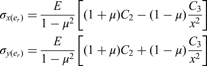
Based on the continuity of stress, the stress at the elastic–plastic interface on the gob-side roadway corresponds to the stress at the initial horizontal position of the elastic zone on that side. At an infinite distance within the elastic zone, the corresponding vertical stress equals the average stress σ1, experienced by the coal pillar. According to the previously mentioned stress boundary conditions, the stress in the elastic zone of the coal pillar adjacent to the roadway is determined as follows:
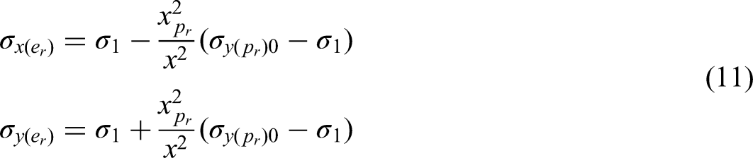
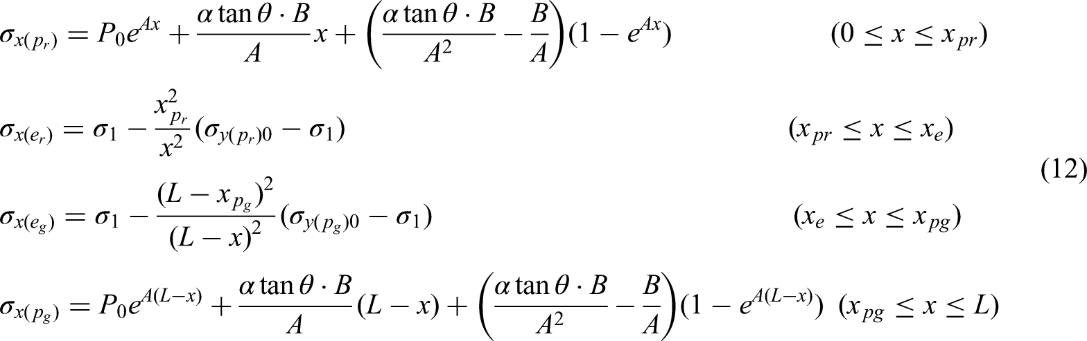
Similarly, the stress distribution in relation to the coal pillar adjacent to the gob side is derived. Ultimately, the formula for the stress distribution of the coal pillar is obtained as follows:
X-direction:
Y-direction:
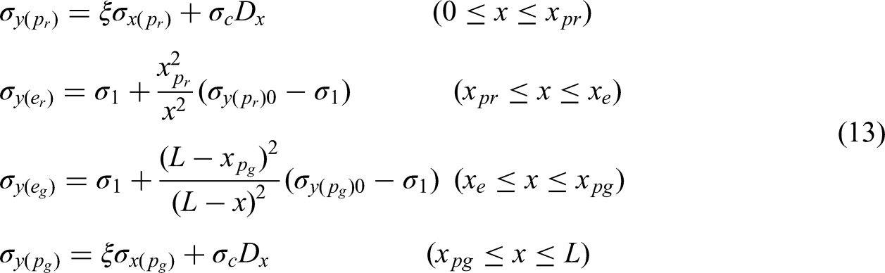
In the equation,
Impact of parameter variations on stress distribution in coal pillars
Engineering simulation of coal pillar stress distribution
The increase in the width of coal pillars enhances their bearing capacity, which subsequently affects the roof rotation angle. To quantitatively analyze the relationship between coal pillar width and roof rotation angle, a 3DEC numerical simulation model was developed based on the mining conditions of the 6315 working face in a coal mine. The simulation used tetrahedral elements with a side length of 2 m for the mesh, and adopted a force imbalance ratio of 1 × 10⁻⁴ as the convergence criterion. The dimensions of the model are 200 m × 200 m × 105 m (length × width × height), as illustrated in Figure 3.
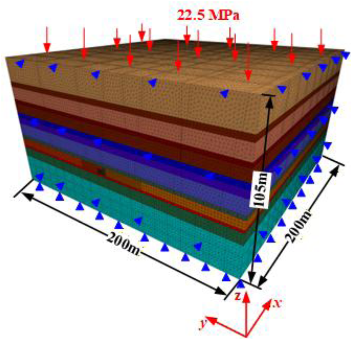
Three-dimensional view of the numerical model.
Based on the geological conditions of the 6315 working face, the average burial depth is 960 m. Given that the dimensions of the model exceed the actual extent of the working face, a unit weight of 25 kN/m3 was applied in the simulation, resulting in an in-situ stress within the coal seam of up to 24 MPa. To account for the effects of the overlying strata, a vertical stress of 22.5 MPa was applied to the model's top surface. The front, rear, left, and right boundaries were constrained in the horizontal directions, while the bottom boundary was fixed in the vertical direction. The width of the coal pillar between the goaf and the 6315 working face was designated as the simulation variable, with values set at 3, 5, 8, 10, 15, and 20 m. The simulation procedure commenced with the establishment of the initial in-situ stress equilibrium, followed by the excavation of the goaf. After the model stabilized, the roadway of the 6315 working face was excavated. Finally, mining of the 6315 working face was conducted in increments of 25 m, totaling 100 m of excavation.
Based on the in-situ geological stratigraphy and adhering to the principle of simplifying analogous rock layers, the lithology of both the roof and floor strata of the coal seam was simplified to a certain extent. Due to the coal seam's minimal dip angle, a dip angle of 0° was utilized in the computational model, and the Mohr–Coulomb constitutive model was employed for the calculations. Following the simplification of analogous rock layers, a total of 13 strata were defined. The physical–mechanical parameters for each simplified rock layer are presented in Table 1.
List of physical and mechanical parameters of rock strata in the model

By conducting on-site geological and rock exploration on the 6315 working face of a certain mine and conducting mechanical tests, relevant rock physical parameters were obtained. According to the key stratum theory, the main key stratum supports the gravity of the overlying rock mass, which serves as the primary load-bearing body in the overlying strata, and it directly governs the dynamic variations and non-uniform distribution of loads on the underlying rock mass. Simplifying the rock stratum above the main key stratum into uniformly distributed loads applied to the upper boundary of the model does not compromise the accuracy of the simulation results. Therefore, the key stratum theory is first employed to determine the position of the main key stratum, and by applying the principle of simplifying analogous rock layers, the relevant rock strata are simplified accordingly (Xie and Xu, 2019; Xu et al., 2001). Due to the coal seam's minimal dip angle, a dip angle of 0° was utilized in the computational model, and the Mohr–Coulomb constitutive model was employed for the calculations. A total of 13 strata are considered. The physical and mechanical parameters of each rock stratum are shown in Table 1.
The results of the numerical simulation are presented in Figure 4. The fitting analysis revealed a relationship between the roof rotation angle and the width of the coal pillar.
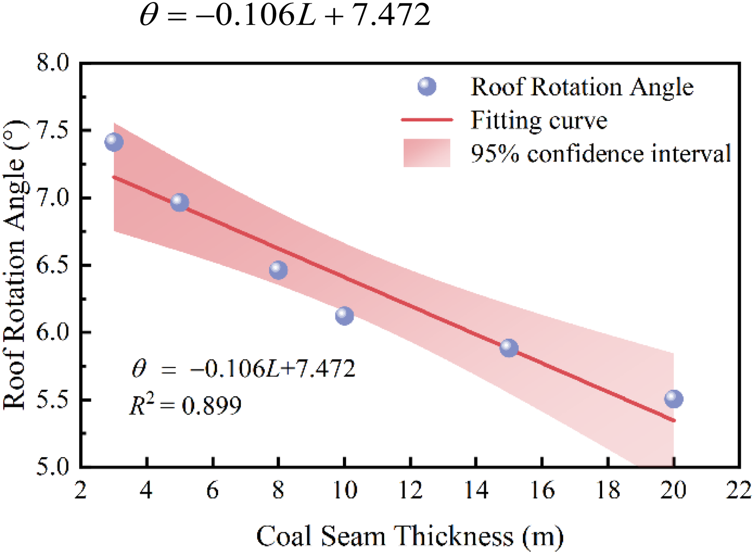
Coal pillar width versus roof rotation angle correlation curve.
Influence of coal pillar width and roof rotation angle on stress distribution within coal pillars
Coal pillars function as load-bearing structures that are characterized by limited dimensions and relatively low bearing capacity. This can result in significant deformation of the surrounding rock in adjacent roadways (Ren et al., 2026). Among the various factors influencing the bearing capacity of coal pillars, pillar width stands out as a crucial controlling parameter. To examine the effect of pillar width on stress distribution, a model tailored to the specific mining conditions of the 6315 working face in a particular mine was developed. Assuming that roof structure movement is negligible, the fundamental parameters utilized in the analysis are detailed in Table 2.
Working condition parameters of a mine.

Assuming coal pillar widths of 3, 5, 8, 10, 15, and 20 m, the vertical stress distribution curves for the coal pillars were calculated using the coal pillar stress distribution model along with the derived vertical stress formula (equation (13)), as illustrated in Figure 5. In the absence of roof structure movement, the vertical stresses within the plastic zone of pillars of varying widths significantly increase with increasing distance x. Additionally, the vertical stress at the initial position along the goaf side remains consistent across all pillar widths. When the coal pillar lacks an elastic core, the peak stress increases from 16.409 MPa to 35.853 MPa as the pillar width expands, while the extent of the plastic zone adjacent to the roadway grows from 1.51 m to 5.74 m.
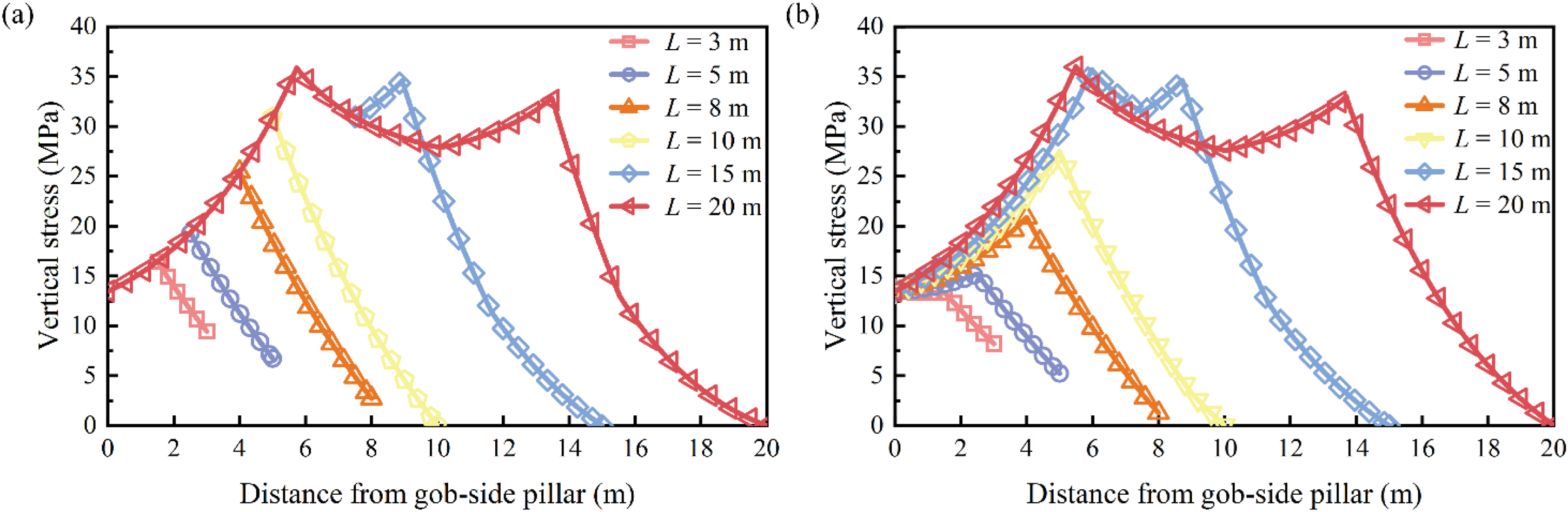
Calculated results of vertical stress in coal pillars: (a) without considering overlying strata movement and (b) with comprehensive consideration of roof rotation angle and coal pillar width.
As the width of the coal pillar increases, the peak stress concentration factor rises from 0.69 to 1.49, reflecting an increase of 115.9%. However, after reaching this maximum value of 1.49, the peak stress concentration factor stabilizes, demonstrating an initial trend of linear growth followed by a plateau. This stabilization, which occurs with increasing width, is primarily attributed to the formation of an elastic core when the width exceeds 15 m. This transition causes the stress curve to shift from a single-peak pattern to a double-peak pattern. Beyond this threshold, both the maximum vertical stress within the pillar and the extent of the plastic zone adjacent to the roadway rib cease to increase, while the region of the elastic core continues to expand. Notably, the stress peak near the rib-side surrounding rock is slightly higher than that near the goaf side. This phenomenon arises because a greater pillar width enhances its load-bearing capacity and decreases the roof rotation angle, thereby mitigating the influence of elastic energy release from the roof near the goaf. This difference becomes increasingly pronounced as the elastic core expands.
The roof rotation angle significantly influences the vertical stress distribution within the coal pillar, necessitating the application of the composite method (equation (14)) to refine the calculations of vertical stress distribution. The overall trend remains largely unchanged, as illustrated in Figure 5(b). In scenarios devoid of an elastic core, the coal pillar exhibits a reduced width and an increased roof rotation angle. Under these conditions, roof rotation exacerbates pillar degradation and diminishes its load-bearing capacity. Consequently, compared to the curve that disregards overburden movement, the peak vertical stress of pillars lacking an elastic core is lower. Conversely, when an elastic core is present, the peak vertical stress increases due to the reduced negative impact of roof rotation on the pillar, coupled with the pillar's enhanced bearing capacity.
Influence of coal seam fundamental parameters on stress distribution in coal pillars
As indicated by equation (13), the vertical stress within the coal pillar and the overall extent of the plastic zone are influenced by several parameters, including coal seam thickness, cohesion, internal friction angle, and uniaxial compressive strength. Based on these variables, the evolution patterns of both the vertical stress and the range of the plastic zone are determined, as illustrated in Figure 6.
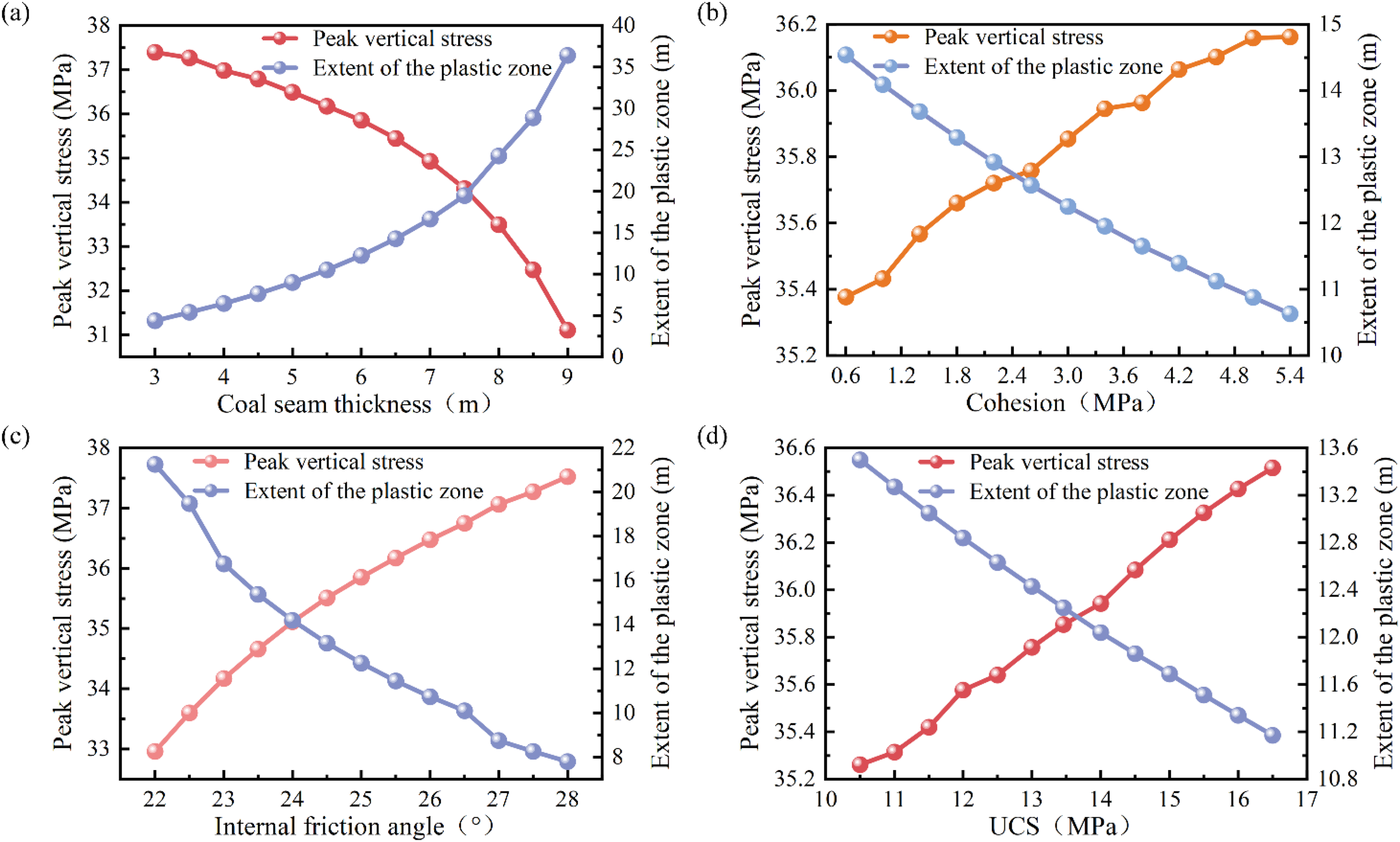
Effects of different parameters on the peak vertical stress and the extent of the plastic zone: (a) coal seam thickness, (b) cohesion, (c) internal friction angle, and (d) uniaxial compressive strength.
As illustrated in Figure 6(a), the peak vertical stress reaches 37.393 MPa when the coal seam thickness is 3 m. As the coal seam thickness increases, the peak vertical stress gradually declines, dropping to 34.931 MPa at a thickness of 7 m, which represents a reduction of 6.58%. Beyond this point, the decline accelerates; at a thickness of 9 m, the peak stress is 31.101 MPa, indicating a further decrease of 10.96% compared to the value at 7 m. Overall, the peak vertical stress exhibits a nonlinear negative correlation with coal seam thickness, while the thickness shows a power-law positive correlation with the extent of the plastic zone. In terms of the coal seam parameters, such as cohesion, internal friction angle, and uniaxial compressive strength, each demonstrates a linear negative correlation with the peak vertical stress and, concurrently, a linear positive correlation with the extent of the plastic zone.
Methods and criteria for assessing the hazard of coal pillar rock burst
Theoretical calculation of coal pillar energy density
The underlying mechanism of rock burst is characterized by the abrupt release of residual energy following the dissipation of stored energy within the coal mass (Shi et al., 2020). The stress state of the coal pillar is the primary factor governing its internal energy accumulation and dissipation mechanisms. The stress distribution characteristics of the coal pillar in the gob-side entry were obtained using a theoretical stress distribution model. Based on the stress distribution features of a coal pillar with an elastic core exhibiting a bimodal structure, a loading–unloading constitutive model was established for analysis, as illustrated in Figures 7 and 8. Based on the stress distribution characteristics of coal pillars, the stress state of pillars in the elastic zone corresponds to the initial loading phase of the coal body, while that of pillars in the plastic zone corresponds to the post-peak phase. The stress increase in plastic-zone pillars corresponds to the loading–unloading stage of the post-peak coal body.
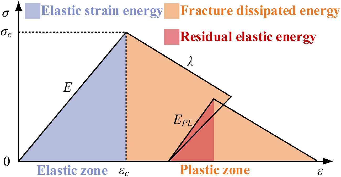
Constitutive model for the loading and unloading of a coal pillar.
Stress distribution characteristics of a coal pillar in the absence of an elastic core.
Under static loading, the coal pillar exhibits an elastic zone with an elastic energy density of UeEL and a plastic zone with a residual elastic energy density of UePL. The fracture energy dissipation density of the coal pillar is denoted as Uf. The corresponding formulae are as follows:


In the equation, σ denotes the vertical stress acting on the coal pillar (MPa), E represents the elastic modulus prior to the peak of the coal pillar stress–strain curve (GPa), λ signifies the softening modulus following the peak of the coal pillar stress–strain curve (GPa), EPL indicates the elastic modulus during subsequent loading after the peak of the coal pillar stress–strain curve (GPa), and εc denotes the strain corresponding to the peak stress of the coal pillar.
Methodology for assessing the hazard of rock bursts from non-elastic nuclear coal pillars
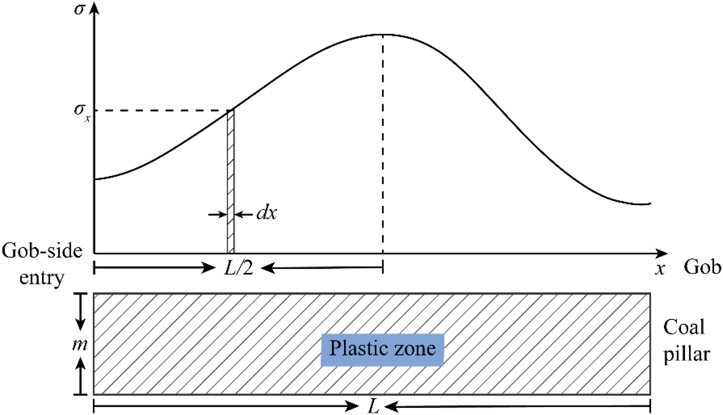
A non-elastic core coal pillar is entirely composed of a plastic zone. Its energy primarily consists of the residual elastic energy density UePL within the plastic zone and the fracture dissipation energy density Uf. Integrating UePL and Uf over the width of the coal pillar gives the elastic energy We stored in the pillar under static loading and the energy Wf consumed during complete fracture:

In the formula, σx denotes the normal stress acting on the unit element at distance x from the coal face (MPa), m represents the height of the coal pillar, x denotes the horizontal distance from the pillar to the longwall face along the roadway, and L denotes the width of the coal pillar.
The energy released upon the disruption of a coal pillar's mechanical equilibrium state consists of the elastic energy stored in the pillar under static loading and the energy imparted during dynamic loading disturbances (Li et al., 2022). The energy required to disrupt this equilibrium encompasses both the energy consumed by complete pillar failure and that absorbed by the support system. The rock burst hazard index of the coal pillar is defined as the ratio of the released energy to the energy expended during disruption.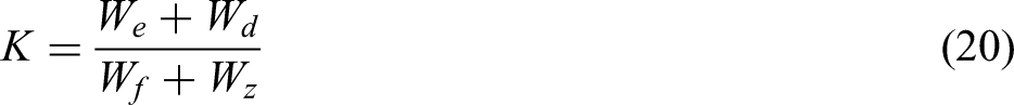
In the equation, Wd denotes the total energy imparted to the coal pillar by dynamic loading disturbances, while Wz represents the aggregate energy that the side support structures of the coal pillar along the longwall roadhead can absorb.
Method for assessing the risk of elastic nuclear coal pillar rock burst
When the width of the coal pillar is sufficiently large, an elastic core develops within it. During rock burst events, this core serves as a source of elastic energy release, while the outer region of the pillar remains in a plastic state. Under rock burst conditions, the plastic zone plays a dual role: it not only releases stored elastic energy but also absorbs a portion of the energy. The corresponding stress distribution within the coal pillar at this stage is illustrated in Figure 9.
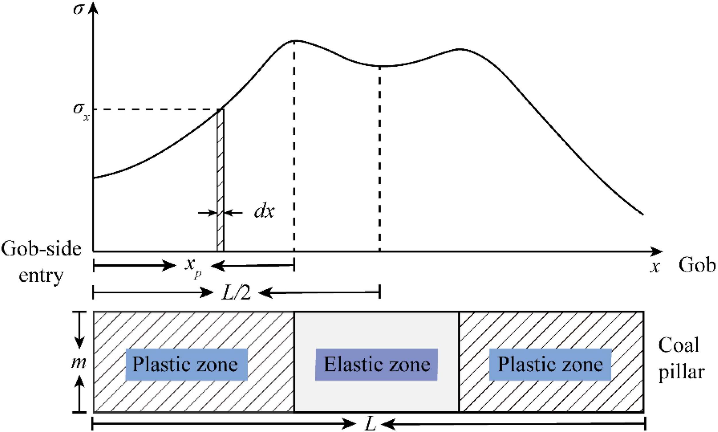
Stress distribution characteristics of a coal pillar with an elastic core.
Integrating the coal pillar energy density formula along the width of the coal pillar yields the elastic energy WeEL stored in the elastic core zone, the elastic energy WePL stored in the plastic zone, and the energy Wf consumed by complete fracture of the plastic zone under static loading.


In the equation, xp denotes the horizontal distance between the elastoplastic interface of the coal pillar and the longwall support of the roadway.
In contrast to non-elastic core coal pillars, those with an elastic core store significant elastic potential energy within their elastic zones. Consequently, when their mechanical equilibrium is disrupted, the released energy encompasses this stored potential. The rock burst hazard index K of a coal pillar is defined as the ratio of the energy released to the energy consumed during the disruption of its equilibrium state.

Case study on coal pillar rock burst hazard assessment
The total energy Wd exerted by dynamic load disturbances on the coal pillar, as indicated by the coal pillar rock burst hazard index, can be calculated based on the location and generated energy of microseismic events, utilizing the following formula:
In the equation, WMS denotes the energy value of the seismic source, X represents the distance between the location of the microseismic event and the longwall tunnel, and η is the energy attenuation index during transmission through the roof strata.
Assuming the most unfavorable conditions, the seismic source energy is set to 1 × 10⁷ J, with the distance between the microseismic event and the roadway taken as 20 m. The energy attenuation index η follows the power-law attenuation model for impact vibration energy in geotechnical media, as validated by Gao et al. (2007). In this model, η is taken as 2 for wave propagation in intact hard rock, a value primarily governed by the geometric diffusion attenuation of stress waves and consistent with the attenuation behavior observed in intact geotechnical materials during in-situ tests. The seismic source is most likely located at the main roof level, and its propagation to the roadway periphery primarily traverses the interface between the main roof and the immediate roof, as well as the interface between the immediate roof and the coal seam. Taking into account the additional energy dissipation caused by the scattering and transmission of stress waves at the rock–coal interface, as well as the energy absorption by the fractured medium, the energy attenuation index η was adjusted to 3. This adjustment is consistent with the significantly increased attenuation coefficients observed in fractured and multi-interface media, as reported in the experimental study by Gao et al. (2007). After accounting for propagation distance attenuation and attenuation across the coal–rock interfaces, the corrected value of Wd is 1250 J.
Based on the corrected vertical stress distributions for coal pillars under different roof rotation angles, as illustrated in Figure 5, and utilizing the coal pillar rock burst hazard assessment method described previously, the rock burst hazard indices for pillars of varying widths are presented in Table 3.
Rock burst risk index of coal pillars with different widths.

As shown in the table, the rock burst hazard index for non-elastic core coal pillars under static loading remains consistently at 0.5. The reason for this phenomenon is that when calculating the rock burst hazard index of an inelastic coal pillar without considering dynamic loading and support conditions, the rock burst hazard index equals the ratio of the elastic modulus E (prior to the peak of the stress–strain curve) to the softening modulus λ (after the peak of the coal pillar stress–strain curve). Once an elastic core develops within the pillar, the rock burst hazard index increases as the coal pillar width expands.
Under combined dynamic and static loading, the energy input to the coal pillar from dynamic loads remains constant. When the coal pillar width is small, the energy stored in the pillar under static loading is less than the energy contributed by dynamic loads. As a result, the primary driving force for coal pillar failure at this stage is attributed to dynamic loading. Therefore, the narrower the coal pillar, the less static energy it stores, resulting in a higher rock burst hazard index. Conversely, when the coal pillar width is larger, the static energy stored in the pillar exceeds the dynamic energy input. Consequently, the primary driver of pillar failure shifts to static loading. Thus, wider pillars store more static energy, which leads to a higher rock burst hazard index.
Based on the conditions of the mine, the coal pillar between the 2305S working face and the 2304S goaf was analyzed in relation to a 2.22 rock burst incident. The relevant parameters are as follows: coal seam thickness m = 9.2 m, coal pillar width L = 4.86 m, upper roof rotation angle θ = 9.0°, coal pillar cohesion C = 3 MPa, internal friction angle φ = 22°, ξ = 2.2, uniaxial compressive strength σc = 8.895 MPa, uniformly distributed roof stress on the pillar σ1 = 24 MPa, elastic modulus before the peak of the pillar’s stress–strain curve E = 2 GPa, and softening modulus after the peak λ=1 GPa. Using the coal-pillar rock burst hazard assessment method described above, the calculated rock burst hazard index is 0.5 under static loading and 1.22 under combined dynamic-static loading. Therefore, while the design of the coal pillar between the 2305S working face and the 2304S goaf appears reasonable when dynamic loading is ignored, the inclusion of dynamic effects indicates a potential for rock burst in the pillar. This conclusion is consistent with the findings of the investigation report on the 2.22 rock burst incident at the mine.
Method for determining the optimal width of coal pillars
Determining the optimal width of coal pillars
When the energy released upon disruption of the coal pillar’s mechanical equilibrium exceeds the dissipated energy, that is, K > 1, the coal pillar is considered at risk of rock burst. Ignoring the influence of the support system, the rock burst hazard of a coal pillar depends solely on the elastic potential energy WeEL stored in its elastic core zone, the elastic potential energy WePL stored in its plastic zone, the energy Wf consumed by the complete rupture of the plastic zone, and the energy Wd supplied to the pillar by dynamic loads. Here, WePL, Wf, and Wd are fixed values, whereas WeEL increases with the width of the pillar. A higher value of K indicates a greater likelihood of rock burst occurring in the pillar. When the coal pillar reaches its limit equilibrium state K = 1, equation (24) reduces to WeEL + WePL + Wd = Wf. Solving this equation yields the minimum and maximum allowable widths for the pillar. For pillars that lack an elastic core, the limit equilibrium condition, combined with the rock burst hazard index, gives We + Wd = Wf.
Determining the optimal width of a coal pillar involves not only energy considerations but also examining how its internal stress varies with width. The vertical stress distribution contours in the coal seam, simulated using the aforementioned numerical model for different coal pillar widths at a working face advance of 10 m, are presented in Figure 10.

Vertical stress distribution contours in the coal seam under coal pillars of different widths: (a) 3 m pillar, (b) 5 m pillar, (c) 8 m pillar, (d) 10 m pillar, (e) 15 m pillar, and (f) 20 m pillar.
The contour plot reveals that with a coal pillar width of 3 m, the entire pillar remains in a plastic state, capable of bearing only limited pressure. The overburden pressure concentrates on the working face, resulting in a stress concentration factor of 2.81, with the peak vertical stress located 7.5 m from the coal face. As the pillar width increases, the peak vertical stress within the pillar rises, thereby enhancing its load-bearing capacity, while the stress concentration factor at the mining rib gradually decreases. When the pillar width reaches 15 m, an elastic core forms within the pillar. At this point, the stress concentration factor at the mining rib decreases to 2.09, representing a reduction of 25.6% compared to the 3 m wide pillar. Conversely, the stress concentration factor within the pillar itself increases to 2.33.
As the width of the coal pillar increases, the region of stress concentration in the working face gradually diminishes, while the peak vertical stress within the coal pillar area exhibits an upward trend. When the coal pillar is relatively narrow, it is unable to fully withstand the pressure generated by the overburden in the goaf. The forces that the pillar cannot support are transmitted through the rock beam structure to the roof above the working face, ultimately impacting the longwall working face. This results in an increase in the stress concentration factor in the working face area. Conversely, as the pillar width increases, its load-bearing capacity improves. Forces from the goaf-side roof then act directly on the upper part of the coal pillar, leading to a continuous increase in the peak stress within the pillar zone. Consequently, the stress concentration region within the coal pillar expands significantly.
Verification of the optimal width of coal pillars
Based on the aforementioned engineering case studies, further calculations were conducted to determine the relationship between coal pillar width and the rock burst hazard index, with the results shown in Figure 11. The analysis indicates that variations in the width of the coal pillars retained in the 6315 working face of a specific mine influence both the internal stress distribution and the energy accumulation state within the pillars, thereby affecting the likelihood of rock burst occurrence. For a retained coal pillar width in the range of 3 to 10.53 m, the entire pillar behaves as a plastic zone, with no elastic core region formed that is capable of efficiently accumulating energy. Within this width range, the rock burst hazard index K, calculated based on energy criteria, consistently remains below 1. This indicates that even under dynamic load perturbations, the energy expended during the coal pillar system's failure process (energy Wf expended during complete fracture of the plastic zone) exceeds the sum of its internally stored releasable elastic energy (WeEL, WePL) and externally input energy (Wd). At this stage, the energy release behavior of the coal pillar remains within controllable limits, presenting a relatively low potential risk of rock burst occurrence.
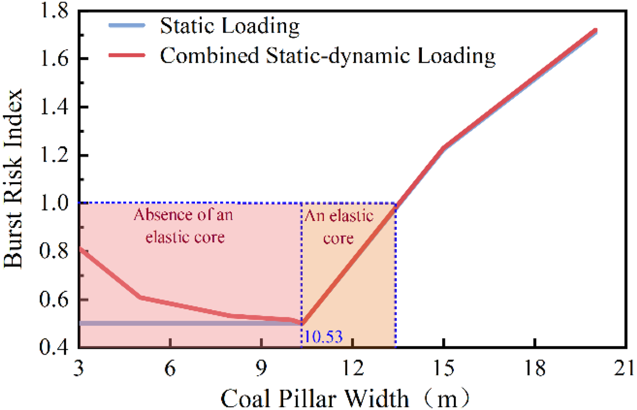
Relationship between coal pillar width and rock burst risk index.
When the coal pillar width exceeds the critical value of 10.53 m, its stability undergoes significant alteration due to the influence of an elastic core. As the coal pillar width increases, a stable elastic core region progressively forms at its center. This elastic core serves as the primary load-bearing element under high ground stresses and mining-induced stresses, while also acting as the main reservoir for elastic energy accumulation. Although the enhanced load-bearing capacity of coal pillars with increasing width helps reduce stress concentration at the working face, the vertical stress peak within the pillars rises markedly. The substantial elastic energy accumulated in the elastic core significantly affects roadway stability, causing the rock burst hazard index K to increase rapidly and exceed 1. When K exceeds 1, it indicates that the energy released upon the disruption of the coal pillar's mechanical equilibrium surpasses the energy that can be dissipated during failure. The surplus energy is then converted into intense dynamic loads, which substantially elevate the risk of rock burst occurrence.
To ensure safe and efficient mining operations, analysis of the coal pillar rock burst hazard index and stress distribution patterns suggests that the optimal retained width for coal pillars in the 6315 working face along the goaf roadway ranges from 3 to 10.53 m. Within this range, the coal pillar maintains sufficient stability to effectively support the overlying strata while preventing excessive elastic energy accumulation caused by an overdeveloped elastic core, thereby reducing the risk of rock burst occurrence.
Conclusion
By incorporating damage variables, a theoretical model was established for the roof structure and the load-bearing capacity of coal pillars. This model derives theoretical expressions for the vertical and horizontal stress distributions within coal pillars, revealing an evolutionary pattern: as the coal pillar width increases, the vertical stress distribution transitions from a “single-peak” to a “double-peak” structure.
Based on the stress characteristics of coal pillars with or without elastic cores, an energy-balanced rock burst hazard index K is proposed. This index quantifies the ratio of potential elastic energy release to dissipated energy under static and dynamic loading conditions. Here, K < 1 indicates pillar stability and the absence of rock burst hazard, providing a quantitative metric for assessing rock burst risk.
By integrating the rock burst hazard index with stress distribution characteristics, a methodology for determining the optimal width of coal pillars was developed and validated through engineering tests at the 6315 working face of a coal mine. Results indicate that the optimal width for the pillar supporting the roadway at this working face ranges from 3 to 10.53 m.
Footnotes
Funding
The authors disclosed receipt of the following financial support for the research, authorship, and/or publication of this article: The study was financially supported by Project of Taishan Scholar in Shandong Province (Grant No. tstp20221126), Youth Innovation Technology Project of Higher School in Shandong Province (2023KJ093), Key Research and Development Project of Shandong Energy Group (SNKJ2025A01-1-R02).
Declaration of conflicting interests
The authors declared no potential conflicts of interest with respect to the research, authorship, and/or publication of this article.