
Abstract
The stability of the surrounding rock in the inclined coal seam stope is crucial for the safety of the gob-side entry. In this article, we systematically analyze the surrounding rock stability of the gob-side entry formed by roof-cutting (GEFR) in an inclined coal seam. We identify three forms of roof structure evolution in the formation process of GEFR and analyze the two main modules affecting the deformation of the surrounding rock structure. We determine the critical elements of surrounding rock deformation in different stages of the GEFR retaining process. Further, we propose a classification of the deformation of the surrounding rock structure of GEFR into stress and structural types during stabilization. We analyze the length of the gangue side's bearing area and calculate the lateral gangue's impact energy. We establish three instability modes of the roof based on the fractured state of the roof structure of the GEFR and provide a mechanical criterion of instability. Finally, based on the results of our theoretical analysis, we propose a control principle for the surrounding rock deformation of GEFR and establish countermeasures for controlling the roof-cutting angle and an asymmetric coupling support system. A field case study was conducted under conditions involving an inclined thick coal seam to investigate the surrounding rock deformation and overburden stress evolution using field monitoring data. The field test results confirm that the control measures of the control roof-cutting angle and the asymmetric coupling support system positively impact the stability of the surrounding rock of the roof-cutting entry in an inclined coal seam.
Keywords
Introduction
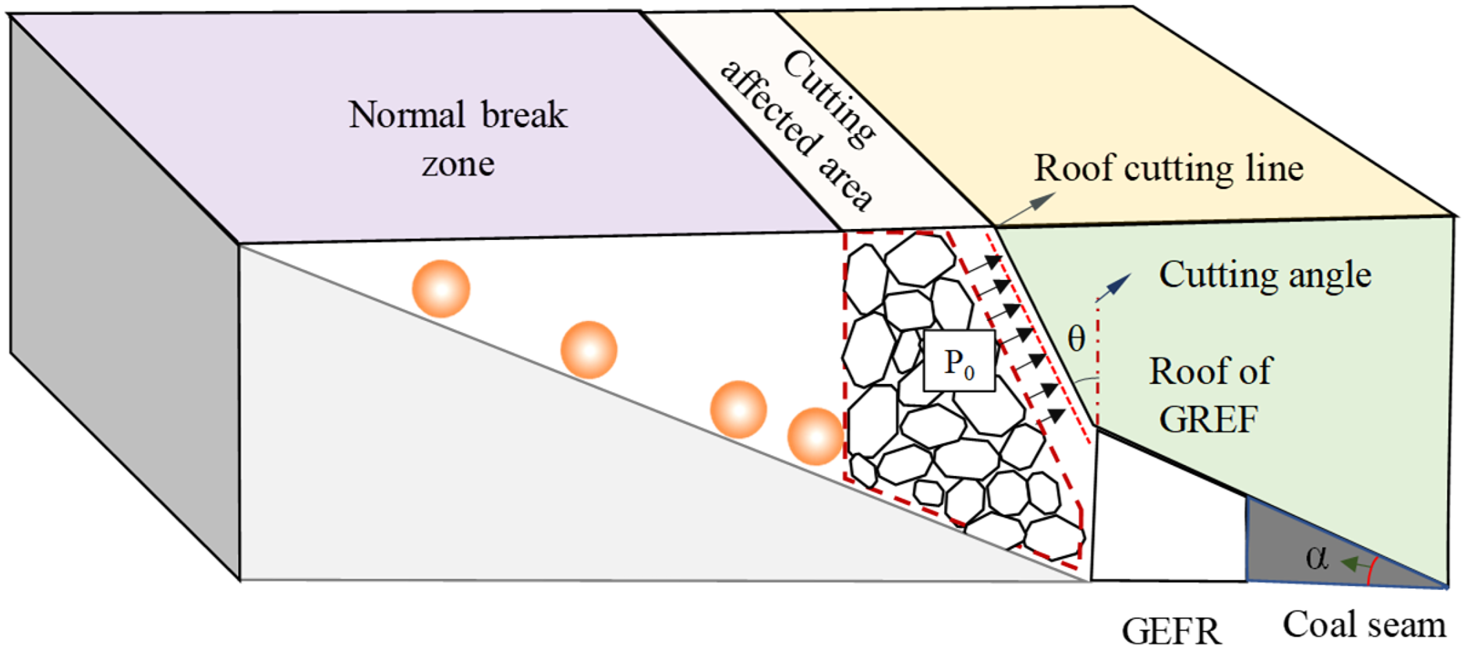
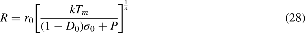
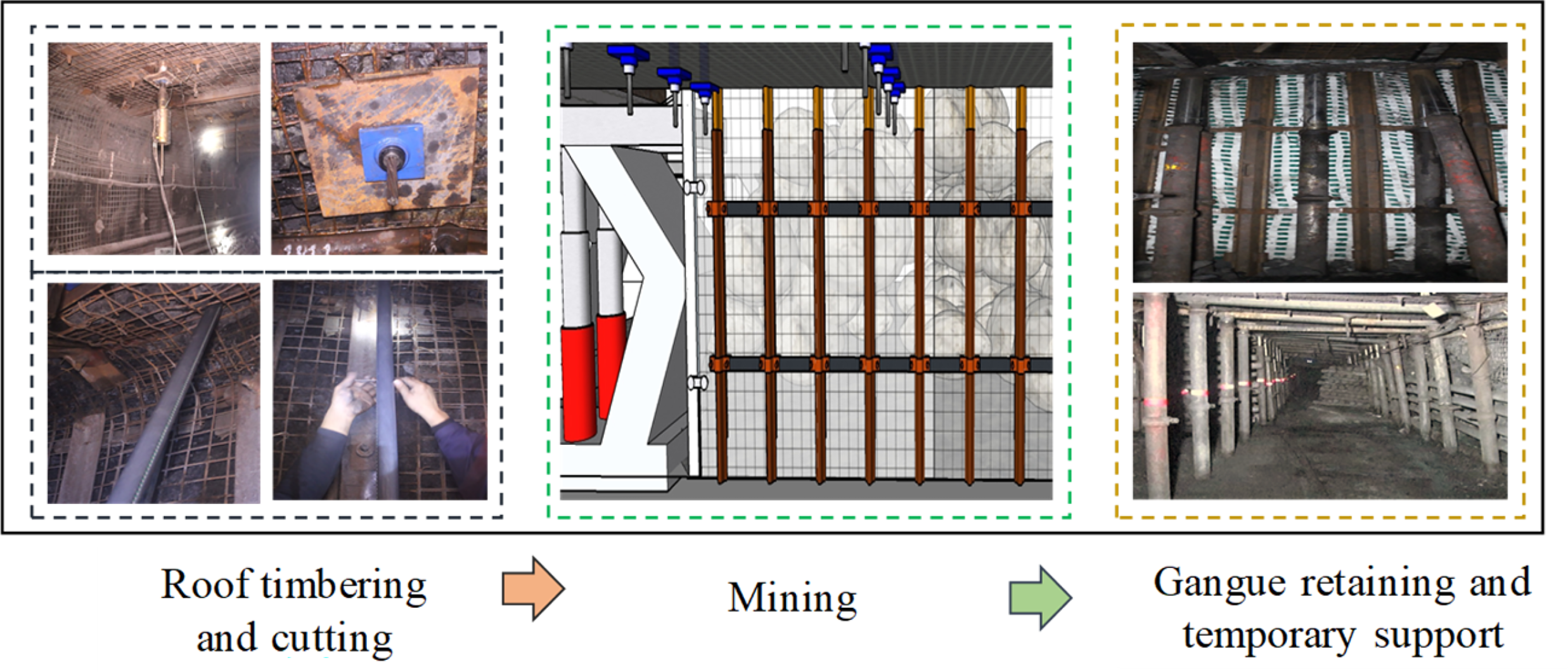
The basic principle of nonpillar mining by gob-side entry formed by roof-cutting (GEFR) is to artificially change the structural state and movement law of roof strata through directional presplitting on the mining side of the entry, with the mining of working face, the rock strata within the range of cutting disturbance collapse under the action of mine pressure, the caving gangue fills the gob under the action of fragmentation and expansion, and the gob-side entry is formed automatically with the help of corresponding supporting facilities. The technical principle of this technology is shown in Figure 1 (Wang et al., 2022; Zhen et al., 2020). This kind of nonpillar mining technology makes use of part of the mine pressure and the collapse gangue. The mine pressure and caving gangue that need to be controlled in the traditional mining process have been transformed into valuable things to realize the formation of gob-side entry. As a new type of nonpillar mining technology, it has been successfully applied under different geological conditions. Including different roof conditions of thin coal seams (Dınçer et al., 2022; Guo et al., 2016; Sun et al., 2014; Wang et al., 2020), medium-thick coal seams (He et al., 2018; Xu et al., 2021), and thick coal seams (Li et al., 2022; Yang et al., 2020; Saqib et al., 2021), the current working faces are near-horizontal coal seams (Candila et al., 2021; Chen et al., 2019; Wang et al., 2021; Zhang et al., 2020), less used in inclined coal seams (Zhen et al., 2019).
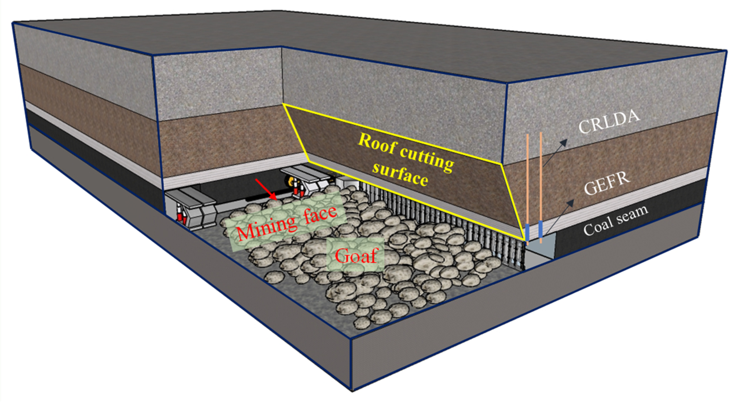
Schematic diagram of the principle of GEFR.
Currently, the primary coal seams being mined in most production sites across China are progressively evolving toward complex geological conditions, including deep and inclined coal seams. Among these, inclined coal seams account for approximately 35% of the total recoverable coal resource reserves. Due to the distinct inclination angle, the caving movement pattern of overlying rock in inclined coal seams differs from that in near-horizontal coal seams. The concentrated stress generated during the movement of overlying rock has a multifaceted impact on the surrounding rock stability of the gob-side entry. Consequently, employing nonpillar mining technology, such as the GEFR method, under inclined coal seams continues to face significant challenges (Metaxas et al., 2023; Mikhaylov, 2023; Saqib et al., 2021; Srbová et al., 2023).
This paper systematically investigates the surrounding rock structure stability and control countermeasures for GEFR in inclined coal seams, building upon existing research. The findings of this study will offer theoretical support for implementing nonpillar mining technology by GEFR in inclined coal seams. This research holds substantial theoretical and practical implications for our country's safe and efficient nonpillar mining of inclined coal seams.
Structural characteristics of surrounding rock of GEFR in the inclined coal seam
Roof structure evolution process of GEFR
Under the joint influence of construction technology and overburden movement of the stope, the main and immediate roofs show different constraint characteristics in different mining stages. It is assumed that the immediate roof on the side of the coal wall and the main roof are always in a clamped support state at different stages. According to the different constraint characteristics of the mining-side roof, the roof structure of GEFR in the inclined coal seam can be divided into three typical states as shown in Figure 2.
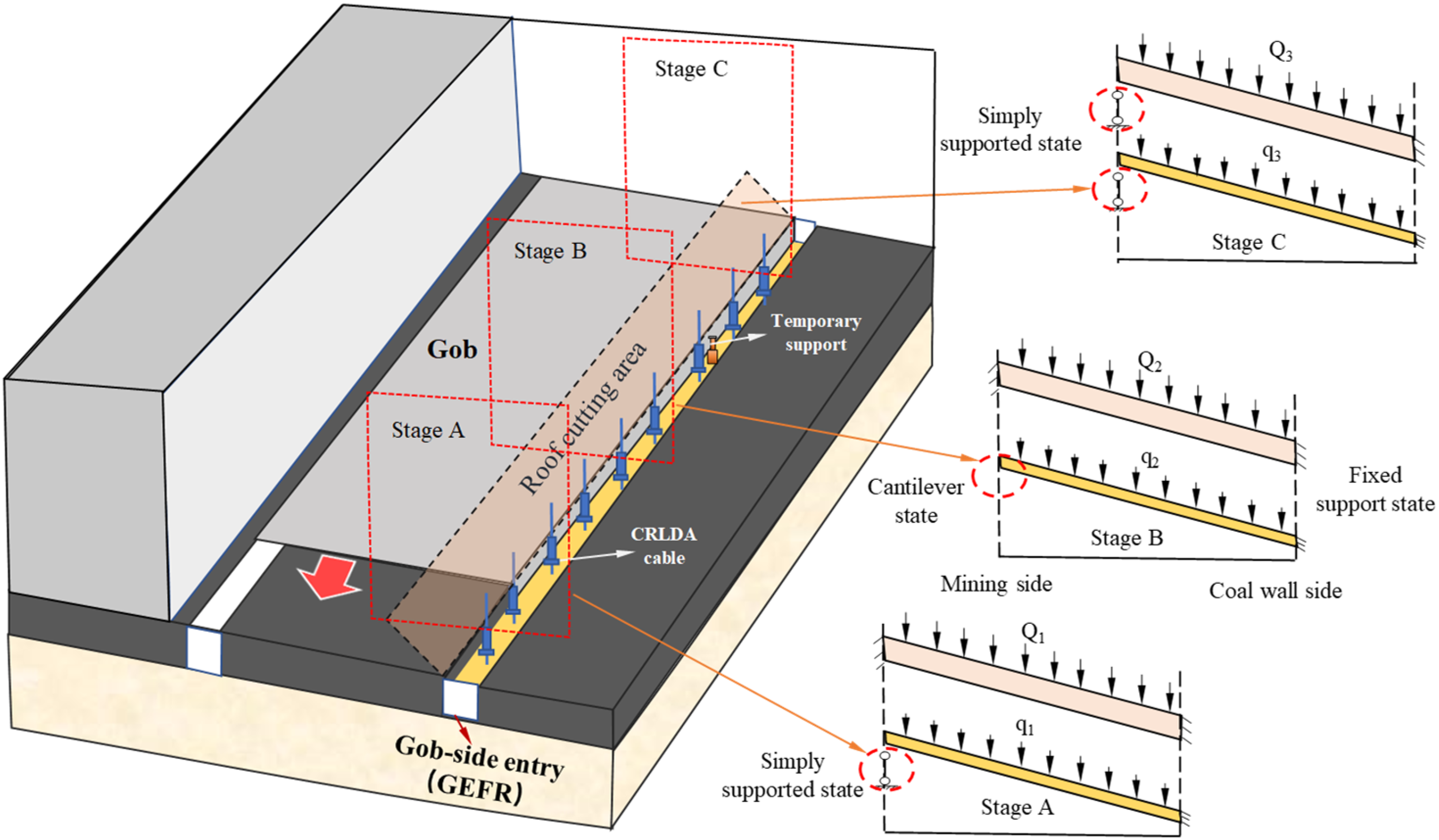
Typical state of the roof structure of GEFR in the inclined coal seam.
Stage A, immediate roof simple supported-main roof clamped support state
In the premining preparation stage, a fracture emerges between the immediate roof and the coal wall after the presplit on the entry roof. This action causes a change in the constraint state of the immediate roof from a clamped support state (prior to cutting) to a simple support state. Meanwhile, the main roof retains its original clamped support state.
Stage B, immediate roof cantilever-main roof clamped support state
As the working face progresses, the immediate roof collapses along the lateral cutting line, causing the immediate roof on the cutting side to transition from its original simple supporting status to a cantilever state. The main roof remains in a clamped support state. Concurrently, the surrounding rock of the GEFR enters a dynamic pressure stage.
Stage C, immediate roof simple supported-main roof simple supported state
When the main roof beam above the GEFR reaches its failure limit, the fractured main roof transitions from its original clamped support state to a simple supporting status. Concurrently, as the main roof's fractured rock block rotates and subsides, the surrounding rock of the GEFR enters a stage of intense dynamic pressure that results in significant deformation of the surrounding rock, as the immediate roof of the GEFR comes into contact with the gangue and becomes progressively compacted. The support force provided by the gangue to the key block continuously increases until a new equilibrium structure is established. At this point, the immediate roof changes from a cantilever state to a simple supporting status, and the surrounding rock structure of the GEFR tends to stabilize.
From the analysis above, it is evident that the constraint states of both the immediate and main roofs undergo continuous changes as the surrounding rock structure of the GEFR stabilizes within the inclined coal seam.
For the overall structure of the surrounding rock of the GEFR, the immediate roof and the main roof belong to the critical members of the whole structure, and their constraint state changes, resulting in a change in the connection mode of the components. It has a specific influence on the strength of the surrounding rock and changes the ability of the structure to resist damage, which is bound to affect the stability of the whole structure. Consequently, it is crucial to elucidate the structural deformation characteristics of the surrounding rock during different loading stages to effectively manage the stability of the GEFR in inclined coal seams.
Analysis of key factors of surrounding rock deformation in different stages
The surrounding rock structure of the GEFR is divided into two modules for analysis to ensure the stability of the surrounding rock during entry retaining progress, based on the nonpillar mining technology of GEFR and the stable structural characteristics of the surrounding rock. Module I was the composite beam structure, including the GEFR's immediate and main roof. Module II was the bulk wall consisting of the gangue on the gob side, with the specific structure illustrated in the accompanying Figure 3.
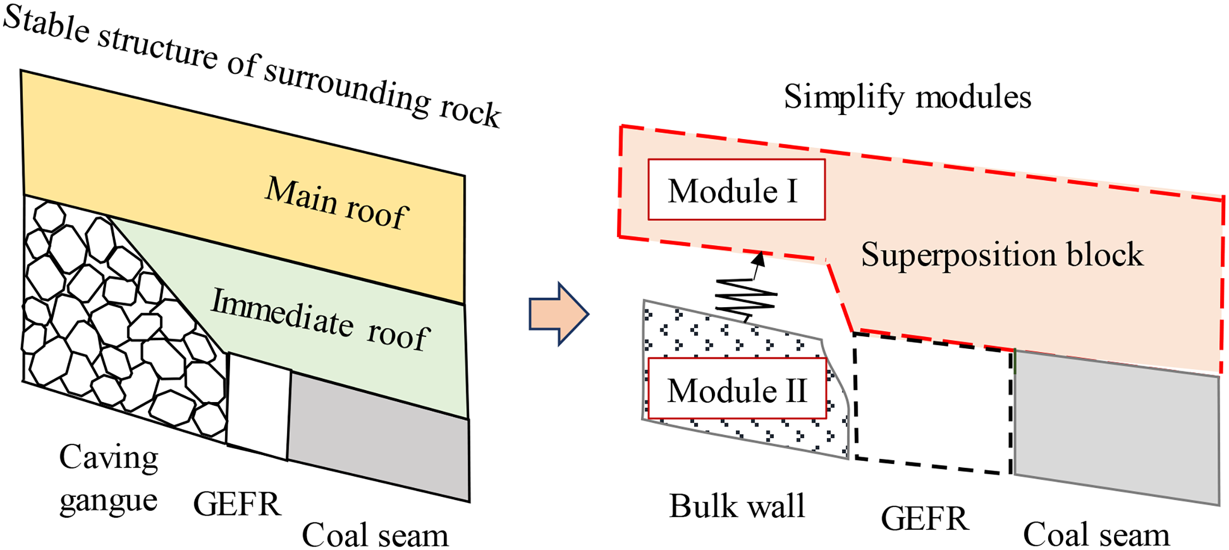
Simplified structure of surrounding rock of GEFR.
Module I deformation analysis
The primary factors controlling the deformation of the key module throughout the GEFR retaining process are analyzed based on the differing constraint states of the roof structure. For Module I, the immediate roof of the GEFR is simple support at one end and clamped support at the other end during Stages A and C, and Stage B features a cantilever at one side and a clamped support at the other. The main roof is in a clamped support state at both ends during Stages A and B, transitioning to a simple support state at one end in Stage C.
Assuming that the width of the GEFR is
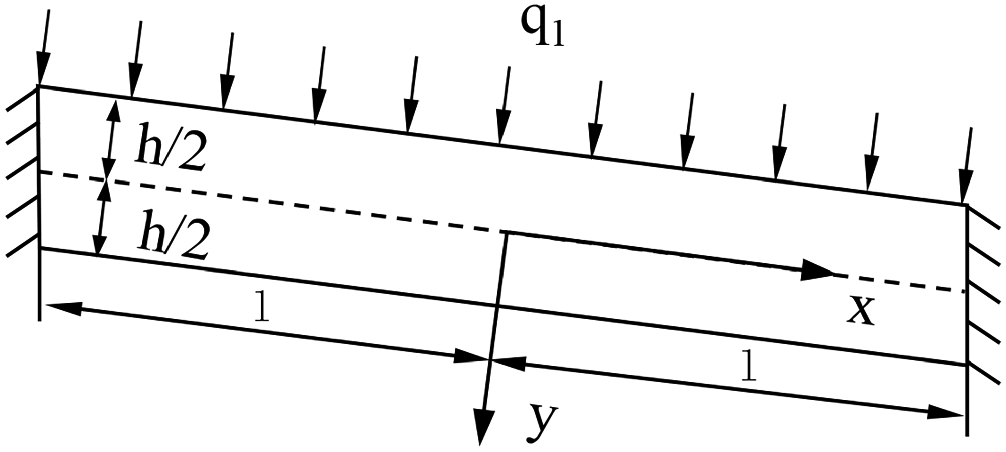
Mechanical model of the roof structure of GEFR in an inclined coal seam.
Based on the theory of elasticity, a stress function φ is introduced:


During Stage A, based on the analysis of the deflection expression provided earlier, it can be concluded that the immediate roof deflection is greater than the main roof deflection under specific overlying loads in this stage. Additionally, the maximum deflection of the immediate roof is observed to be in the central region. Therefore, to ensure the surrounding rock's stability, focusing on the central region during this stage is recommended for effective rock stability control.
In Stage B, following immediate roof collapse resulting in a cantilever state, it can be observed from equation (4) that the maximum deflection occurs on the side of the cutting side. The immediate roof is affected by both the friction of the lateral rock and the stress disturbance of the stope, leading to its deformation being more extensive than that of the main roof. Therefore, at this stage, the support system should exert a more significant support reaction force on the cutting side to prevent separation and maintain the overall stability of the surrounding rock structure. From the analysis above, it can be inferred that the deformation of the surrounding rock in Stages A and B is induced by force exerted, which can be uniformly classified as stress deformation.
During Stage C, fracture rotation and subsidence occur after the main roof reaches the limited step distance until a new equilibrium structure is reached and is no longer in motion. At this stage, the deformation of the surrounding rock is primarily caused by the transformation of the new and old equilibrium structures, which can be classified as structural deformation. Specific measures should be focused on facilitating the contact of the main roof with the gangue to reduce subsidence space and maintain the surrounding rock's overall stability. Figure 5 illustrates the key factors involved in Module I structural deformation.
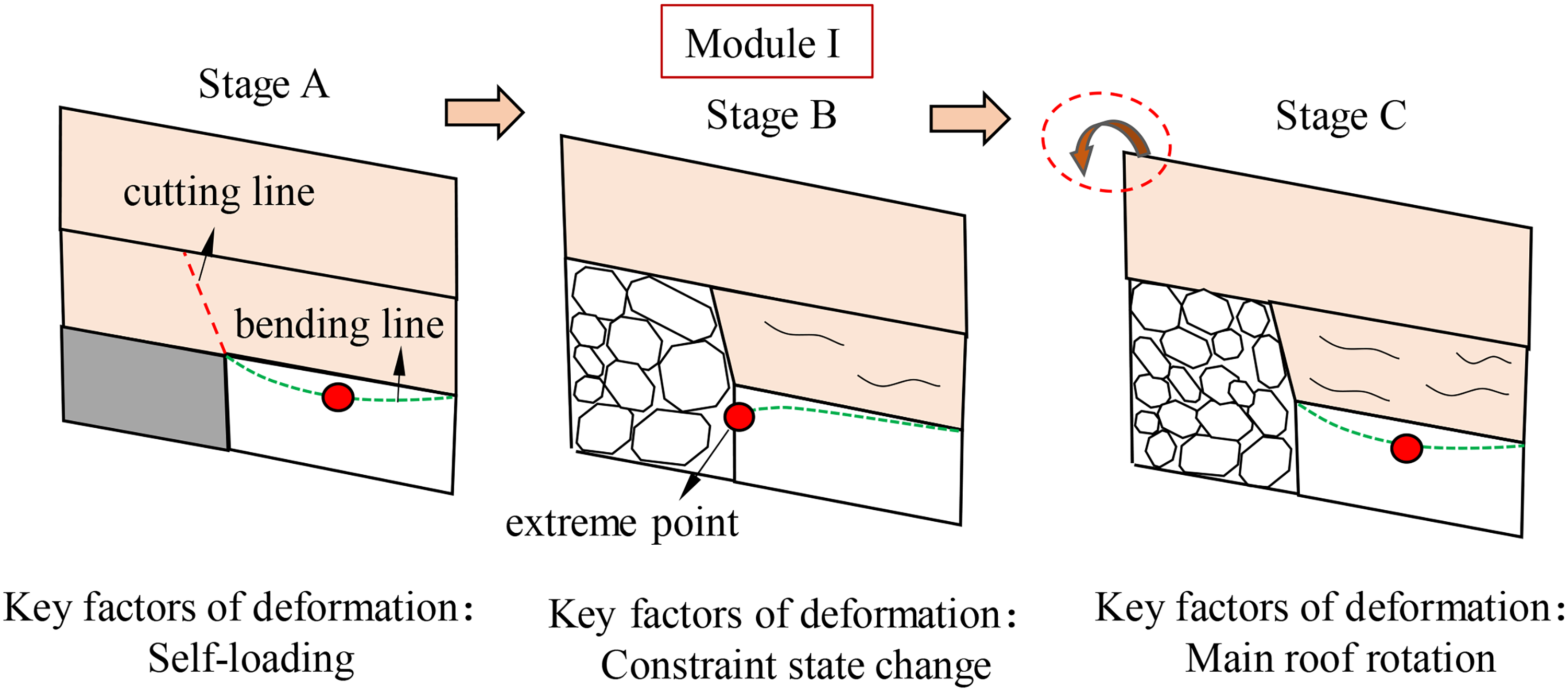
Key deformation factors of Module I.
Module II deformation analysis
In Stage B, the rock mass progressively collapses and accumulates, forming Module II. During this stage, the supporting structure of Module II is subjected to a significant impact resulting from the lateral collapse and slippage of gangue. The sudden impact load is intense, and severe impacts may readily lead to structural instability. Consequently, the supporting structure of Module II should possess robust lateral resistance during this stage.
During Stage C, the bulk wall is formed and undergoes continuous compaction under lateral pressure. Creep stress arises in the progress of gangue compaction, which gradually increases the lateral pressure on the supporting structure and results in deformation. At this stage, the lateral supporting structure must possess a specific load-bearing capacity to accommodate the deformation until the gangue expansion coefficient attains a residual state upon the completion of overlying strata movement, Module II approaches stability, and the critical factors influencing Module II structural deformation are illustrated in Figure 6.
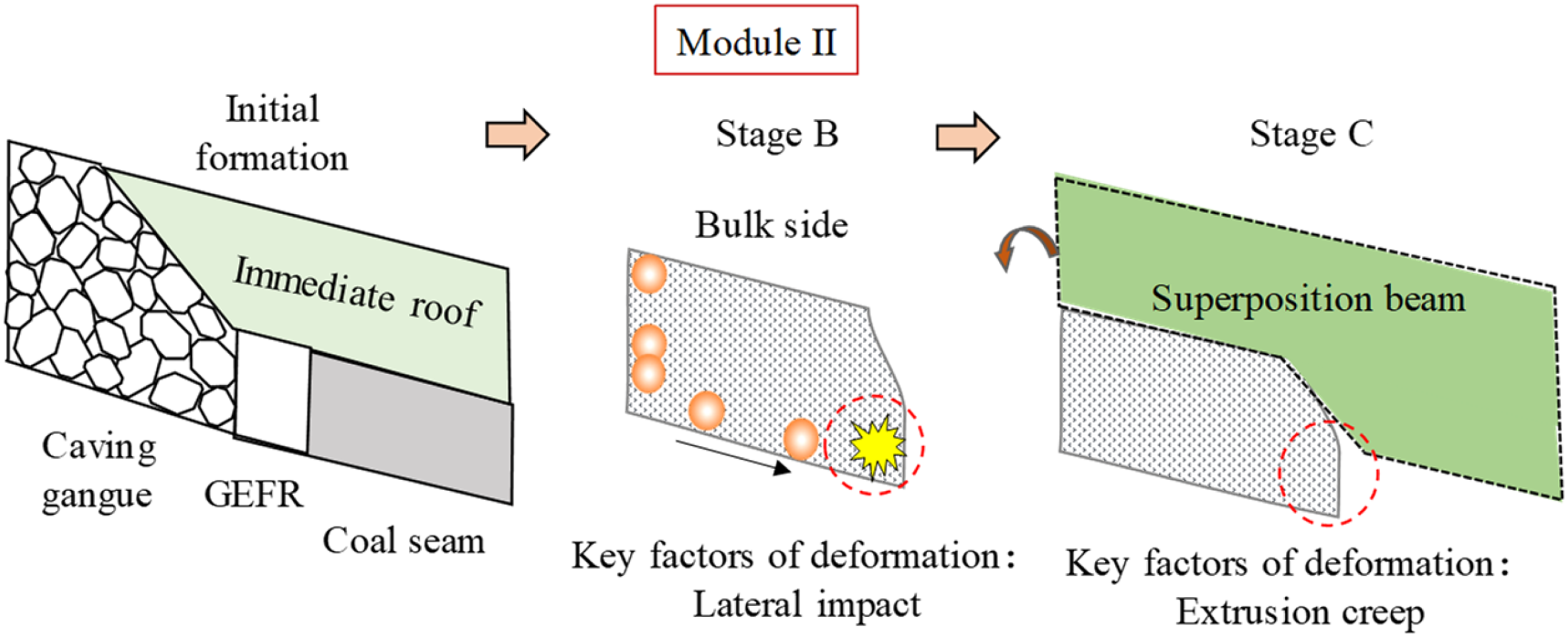
Key deformation factors of Module II.
Module II is a crucial component of the surrounding rock for the GEFR. The difference in load types between Stages B and C significantly impacts the stability of the surrounding rock structure during stabilization. Specifically, the impact load of Stage B and the creep load of Stage C have varying effects on the strength of Module II. Therefore, to ensure stability, it is essential to implement corresponding supporting measures based on the loading types of each stage.
The key factors contributing to the surrounding rock deformation of GEFR in inclined coal seams vary across stages. The deformation of the surrounding rock structure can be primarily classified into two categories during the stable deformation process: stress-induced and structural-induced. The loading of the rock itself causes stress-induced, and structural-induced deformation occurs when a new equilibrium structure is established within the mined-out space. For Module I, Stages A and B deformation is predominantly stress-induced, while Stage C is primarily structural-induced. Module II deformation is mainly stress-induced and can be further divided into abrupt and slow deformation. Abrupt deformation results from the impact dynamic load of lateral gangue, while slow deformation is caused by compressed gangue during the overlying rock stabilization process. The primary controlling factors of surrounding rock deformation are determined by synthesizing the deformation classifications and analyzing the stress characteristics of different modules. This information can guide subsequent research on surrounding rock control measures.
Roof instability mode of GEFR in an inclined coal seam
During the stabilization process of GEFR roof structures in the inclined coal seam, the immediate roof and main roof exhibit varying constraints. Consequently, alterations in structural support forms inevitably result in changes to stress distribution within the structure that cause different instability modes to impact the stability of the surrounding rock, The integrity of Module I is affected after failure, and the overall strength of the surrounding rock structure is bound to be reduced. As a critical component affecting the surrounding rock structure of GEFR, the change in its integrity plays a decisive role in the structure's overall stability. Therefore, exploring the possible form of its instability mode is necessary. And now, these specific instability modes are analyzed. For the immediate roof section of the GEFR, its thickness typically exceeds the span, allowing the immediate roof after cutting to be considered a “deep beam.” The failure at the coal wall's side is primarily attributed to shear forces rather than bending. The overall instability modes of GEFR structures can be classified into the following three types:
Instability Mode I: Within the range of roof cutting, the key block of the main roof above the entry experiences slippage and loses stability at the coal wall's side due to shear deformation failure. Simultaneously, the immediate roof undergoes shear deformation failure at the coal wall's side, as shown in Figure 7. This instability mode primarily results from the load resistance to shear between the key blocks being insufficient to counteract the key blocks’ shear forces. Instability Mode II: Within the roof-cutting scope, the main roof's key block above the entry exhibits significant rotational deformation at the coal wall's side due to extrusion failure. Concurrently, the immediate roof experiences shear deformation failure at the coal wall's side, as shown in Figure 8. This instability mode primarily results from the extrusion between key blocks surpassing the shear strength of the rock mass, leading to the extrusion and fragmentation of the main roof strata. Instability Mode III: Within the range of roof cutting, shear deformation failure occurs at the immediate roof coal wall's side. The insufficient strength of the roof support in the entry leads to the shallow collapse of the immediate roof, as shown in Figure 9. This issue can be avoided by reinforcing the entry's roof support.
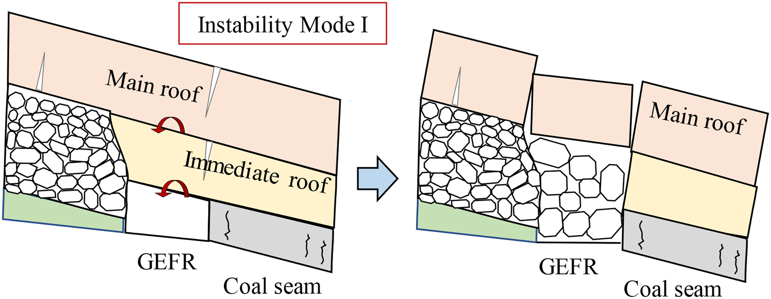
Schematic diagram of instability Mode I.
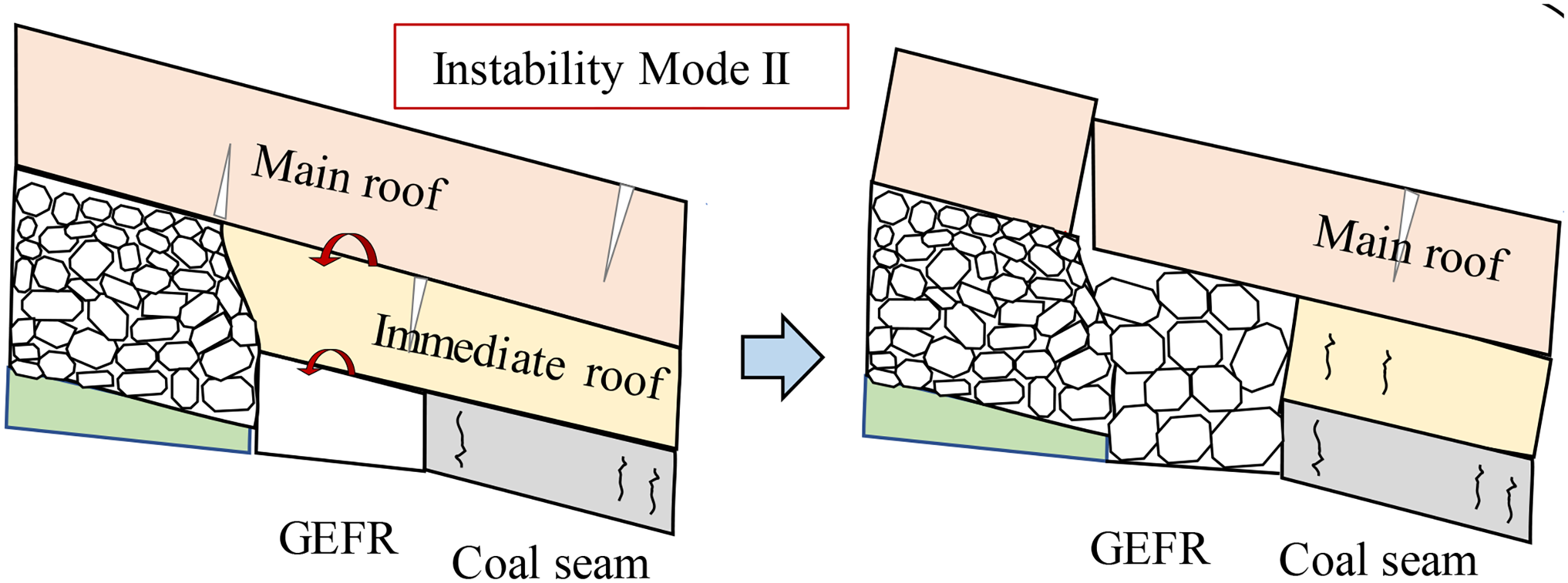
Schematic diagram of instability Mode II.
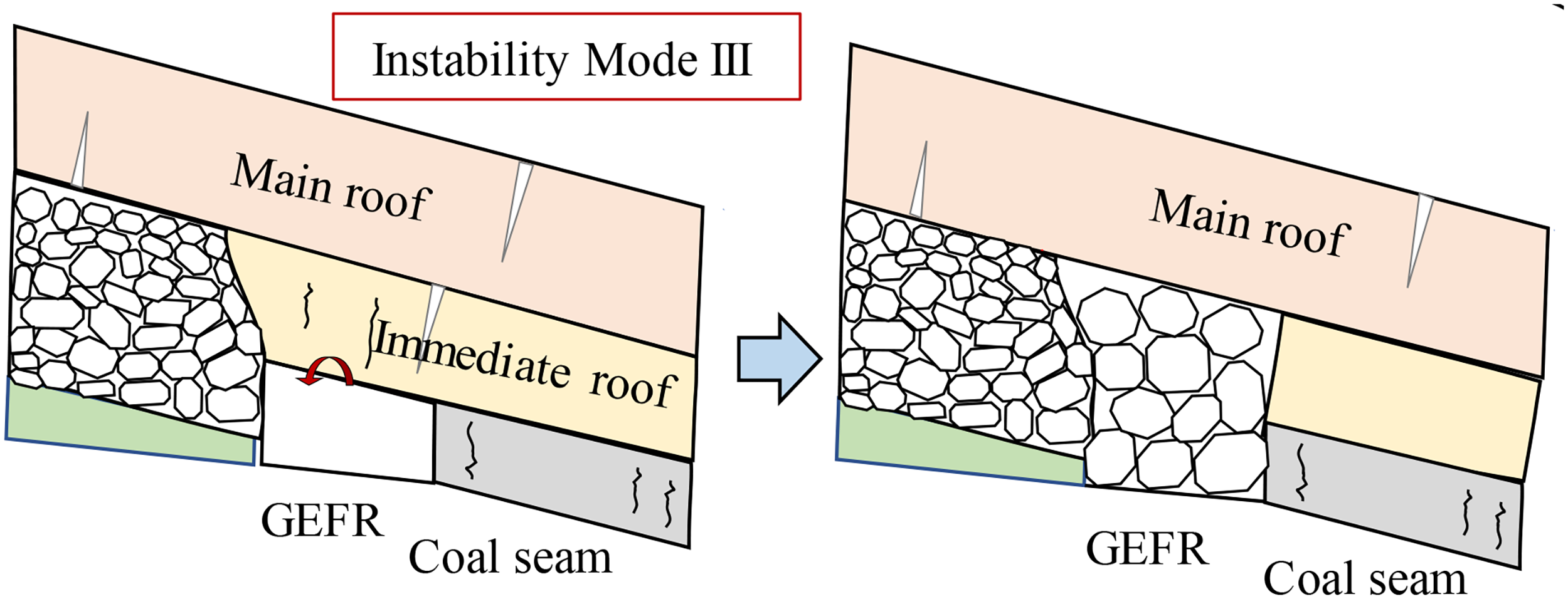
Schematic diagram of instability Mode III.
Analysis of the length of load-bearing area of bulk side
For Module II, during the stabilization process, gangue is extruded by the overlying strata within a specific range near the cutting side, resulting in slow deformation. The extrusion length of the overlying strata determines the total slow deformation of Module II when the expansion coefficient is established. The fracture location of the overlying strata beam determines this extrusion length. Meanwhile, the structural deformation of Module I primarily depends on the rotation and subsidence of key blocks caused by the main roof fracture. Consequently, determining the fracture location of the overlying strata is crucial for controlling the surrounding rock deformation. In this analysis, the GEFR refers to the lower side of the working face.
The main roof fracture exhibits an “O-X” shape, with the GEFR situated beneath the triangular block formed by the main roof fracture. Consequently, the gangue under the triangular block is subjected to compression from the rotary subsidence movement, resulting in a dense area of length La. The bulk wall of the GEFR borders this area on one side, and the main roof fracture position touches the gangue point on the other, as illustrated in Figure 10.
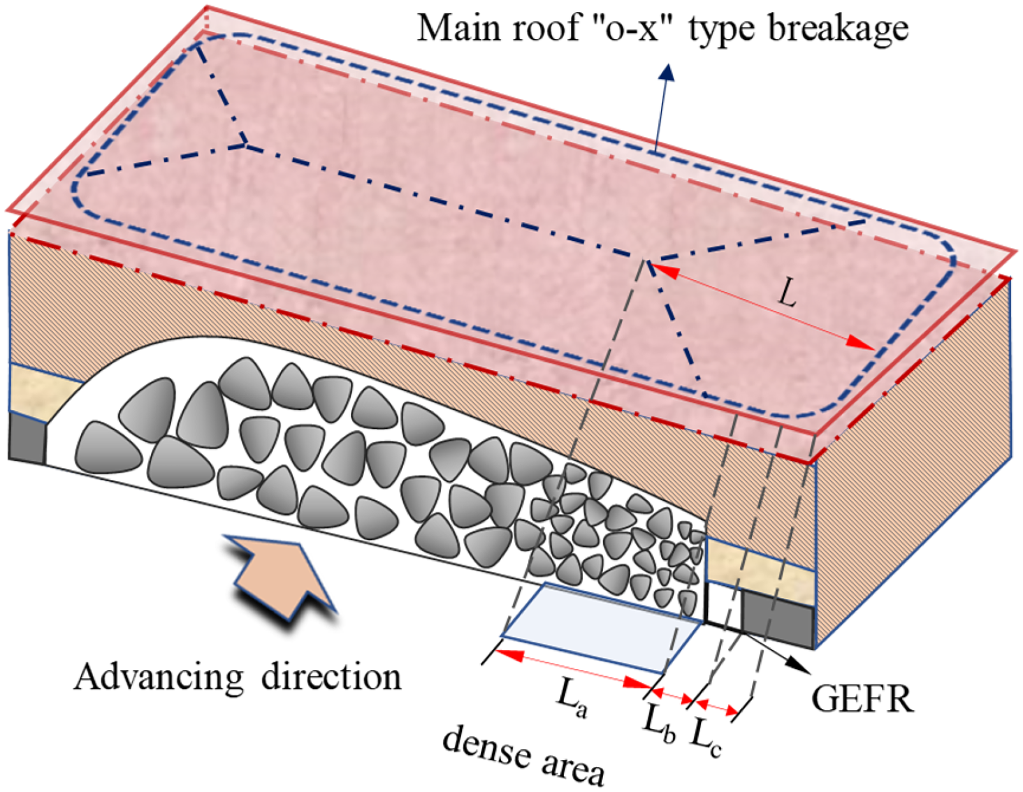
Schematic diagram of dense area of gangue in gob.
The length of the dense gangue area is created by the rotary subsidence of the triangular block, which forms after the main roof fracture. Consequently, this length is closely associated with the length of the main roof's lateral triangular block. A model is established to calculate the length of the dense gangue area, as depicted in Figure 11.
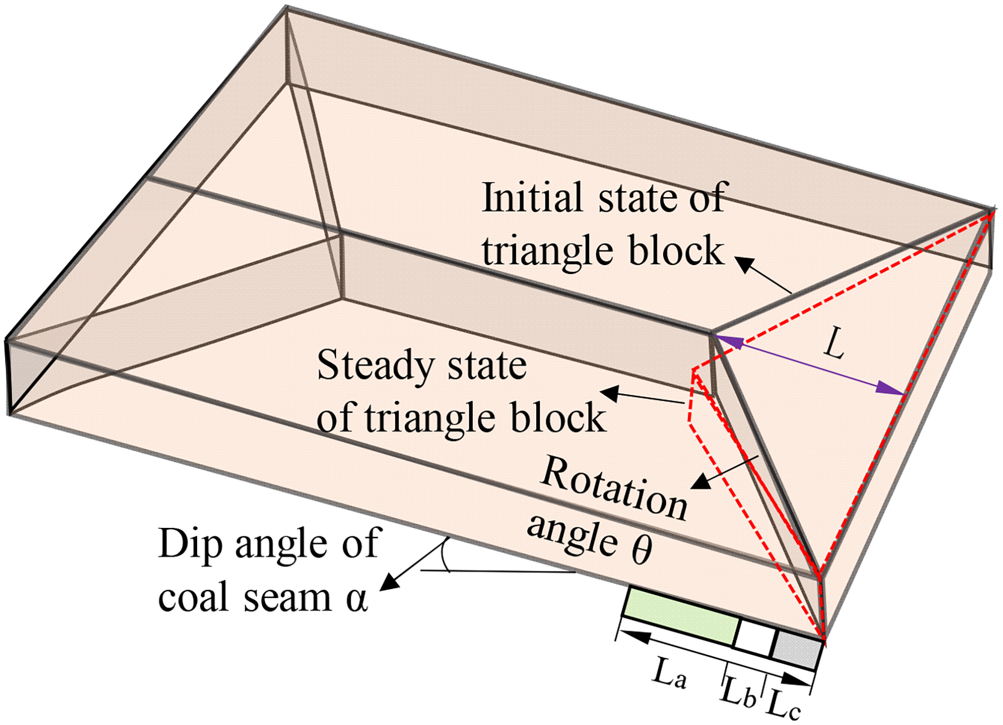
Lateral triangular block model of main roof failure.
According to the above picture, the length of the dense area filled with gangue satisfies the relationship:

The maximum bending moment of the fixed beam occurs at both ends of the beam,
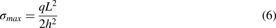
By substituting equation (7), equation (8) into the preceding equation, the following result can be obtained:
Stability analysis of surrounding rock of GEFR in the inclined coal seam
Mechanical analysis of roof instability mechanism of GEFR
The mechanical model of the roof structure for GEFR in an inclined coal seam is established to analyze the instability of Mode I and II, as illustrated in Figure 12. In the figure, q0 represents the load transferred from the overlying strata to the key block of the main roof, with the load assumed to be uniformly distributed. Ge and Gd denote the deadweight load of the main roof key block and the immediate roof above the GEFR, respectively. QAB and QCB represent the shear forces between the front and rear key blocks A, C, and B, while TAB and TCB signify the extrusion pressures between these key blocks. Fs corresponds to the ultimate shear stress that causes shear failure of the immediate roof, and fm is the supporting load of the coal seam on the immediate roof, assumed to be linearly distributed in a triangular pattern. fg indicates the supporting load of the gangue on key blocks, assumed to be uniformly distributed. Pi is the supporting load of a single supporting structure of the GEFR (either single support or anchor cable support). Le represents the length of key blocks, while he and hd are the thicknesses of the basic and immediate roof strata, respectively. xi is the distance from the load point of the ith single supporting structure in the entry to the edge of the coal wall, θ denotes the dip angle of the rock stratum, and β corresponds to the roof cutting angle.
Mechanical model of roof structure of GEFR in inclined thick coal seam.
Based on the geometric relationship depicted in the figure, the dead load (Ge) of the main roof's key block can be expressed as follows:

The dead weight (Gd) of the GEFR's immediate roof strata is

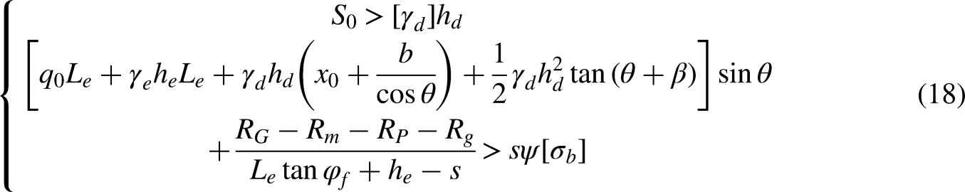
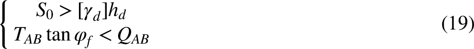
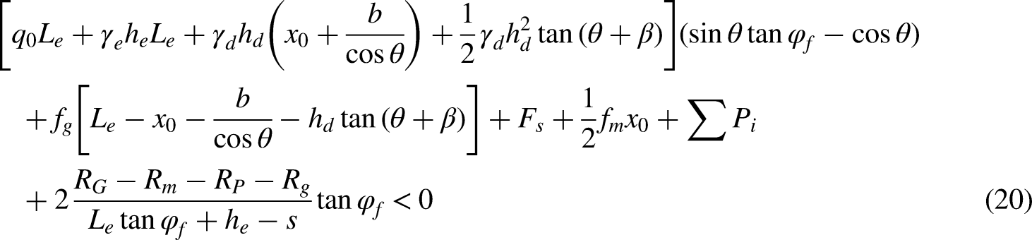
The equilibrium condition of the superimposed block satisfies the following equation:

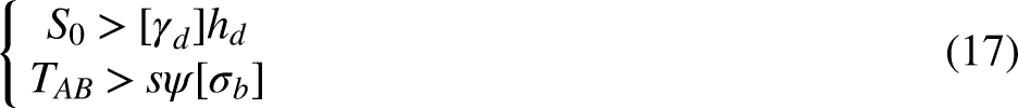
Bring the relevant physical quantities into equation (17), the instability conditions corresponding to Instability Mode I can be derived as follows:
A mechanical model of the immediate roof structure of GEFR in an inclined coal seam is established to analyze the Instability Mode III, as depicted in Figure 13. The immediate roof is considered to be in the most disadvantageous state for ease of analysis, neglecting the enhancement effect of active support on roof-bearing capacity and disregarding the bending and shear strength of the immediate roof due to its significant shear deformation at the side of the coal wall. The primary factor assumed to lead to immediate roof instability is a component of the self-weight load of the immediate roof along the y-axis direction.
Mechanical model of immediate roof of GEFR.
The following formulas can be obtained from the static equilibrium condition:
Analysis of gangue impact
When noncoal pillar mining by GEFR is applied in an inclined coal seam, the roof within the range of influence of presplitting blasting will collapse earlier than the roof outside the influence area. This collapse gangue will quickly accumulate to form a cushion layer that can isolate the impact caused by the collapse gangue in the middle and upper parts of the working face. Therefore, this section's analysis focuses on the impact of gangue within the influence range of the presplitting slit, as illustrated in Figure 14.
Schematic diagram of impact of falling gangue on bulk side.
As the gangue collapses, the potential energy of the caving block is converted into kinetic energy. Upon impact with the coal seam floor, the block undergoes a free fall movement and loses a portion of its kinetic energy. Afterward, the direction of movement changes, and the block slides downward along the working face under the influence of its weight. Given that the sliding process is complex and that the influence range of the presplitting slit is small compared to the total length of the working face, it is assumed that the collapsed gangue does not undergo a transition from sliding to rolling. To simplify the calculation process, the following assumptions are made:
The collapsed block does not experience a rolling state during its slide along the coal seam floor. The sliding block is considered to be rigid. The maximum volume of the sliding block does not exceed 2/3 of the mining height. The static friction coefficient of the coal seam floor is constant.
As the roof rock falls and begins to freefall, the potential energy of the collapsed gangue is transformed into kinetic energy. According to the principles of energy transformation, the velocity at which the gangue makes contact with the floor of the coal seam can be calculated using the following equation:
Upon reaching the floor of the coal seam, the gangue collides with it, thereby consuming a portion of its kinetic energy. Subsequently, the gangue continues to move along the inclined direction of the working face at a certain speed. The initial velocity of the gangue can be expressed using the following equation:

When the inclination angle of the working face exceeds the natural accumulation angle of the gangue, the downward sliding process of the gangue is accelerated. Conversely, the downward sliding of the gangue is decelerated. The velocity of the gangue reaching the lower side of the working face can be calculated using the following equation:


To maintain the stability of the entry's surrounding rock and absorb the impact energy, it is essential to ensure that the lateral gangue retaining support system has certain vertical flexibility and lateral bending ability. Additionally, increasing the cushion area's lateral accumulation area should be considered to reduce the impact of the caving gangue on the entry.
Countermeasures for stability control of surrounding rock of GEFR in an inclined coal seam
Surrounding rock control principle
In combination with the analysis presented above, to maintain the structural stability during the prior deformation period of surrounding rock, the basic principles of surrounding rock control for GEFR in inclined coal seam must satisfy the following conditions:
In the initial stage of dynamic pressure influence, lateral support stability should be a primary concern, and appropriate technical measures should be taken to weaken the lateral impact and ensure the stability of Module II. The key block of the overlying rock should quickly touch the gangue and rely on the supporting force provided by the gangue to transfer the fracture location of the key block to the depth of solid coal. A set of surrounding rock support systems with specific compression deformation capacity and high support resistance should be established to avoid the three instability modes of Module I.
Two approaches can be adopted to improve the stability of surrounding rock in the GEFR while meeting the control principles of surrounding rock: (a) optimizing the technical parameters by adjusting the roof cutting angle and optimizing the blasting parameters, and (b) constructing a stable support system for surrounding rock.
Optimization of key parameters of GEFR in an inclined coal seam
Optimization of slit angle
Field experience shows that the selection of the roof-cutting angle should not be less than 5° to avoid the splitting slit's blasting disturbance and the friction effect of the rock mass on the entry's roof during the collapse process. Presplitting blasting with a small slit angle θ can easily damage the entry's roof support near the slit range. Moreover, the small contact area between the caving gangue and the slit surface provides minimal support, leading to poor stability of the surrounding rock. On the other hand, a roof-cutting angle greater than 25° increases the depth of the slit hole to achieve a certain slit height, making on-site construction challenging. Therefore, the optimal slit angle range falls between 5° and 25°.
Increasing the roof cutting angle in inclined coal seams effectively reduces the total amount of initial caving gangue, weakens the impact force, and increases the lateral range. The accumulated caving gangue within the cutting roof's lateral range can form a specific density cushion, which buffers the later caving gangue. This effect is beneficial to the lateral stability of the entry. Figure 15 shows the schematic diagram of the roof support.
Schematic diagram of caving gangue support to GEFR roof.
Optimization of slotting effect
The roof slit effect is crucial in maintaining the stability of the surrounding rock. Within a specific range of the roof, where the cutting effect is good, the gangue collapses in time, enabling immediate contact with the main roof supporting the entry roof and reducing severe deformation of the surrounding rock during dynamic pressure. After explosive blasting in the slotted hole, the rock damage area disturbed by the blasting impact should overlap between the two slotting holes to ensure that the slit penetration crack achieves the desired cutting effect. Figure 16 shows the mechanical model formed by two-slotted hole blasting.
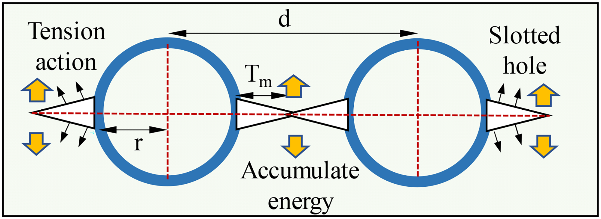
Mechanical model of slotted hole blasting.
The pressure on the shock wave surface of an explosive after blasting can be determined based on the C-J theory of condensed explosives and the theorem of conservation of momentum:
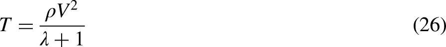
A designated air column is established within the energy-gathering tube to guarantee the effectiveness of the slitting process while maintaining the stability of the entry roof. Consequently, the maximum shock wave pressure exerted on the wall of the slitting hole can be expressed as follows:
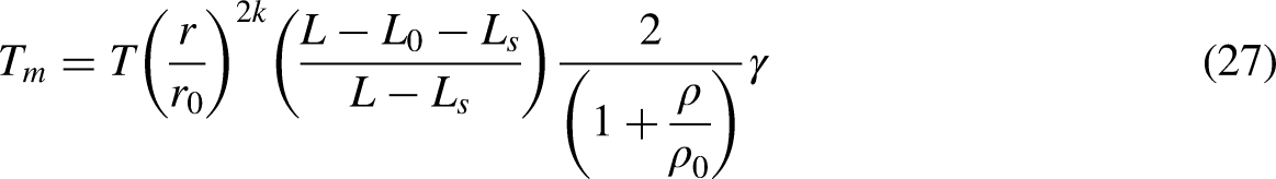
Following the explosive blasting within the slitted hole, the extent of rock damage caused by the detonation wave on both sides of the slit hole can be expressed as follows:
It becomes evident that, in order to ensure effective penetrating cracks between two slitting holes in the entry roof, it is necessary for the distance between these holes to satisfy the following formula:
Construction of surrounding rock support system
The influence of dynamic pressure on the lateral impact during the initial phase of roof-cutting in GEFR can be mitigated by adjusting the cutting angle and blasting parameters. In light of the structural deformation and severe mining stress experienced during the middle and later stages of dynamic pressure impact, it is essential to construct a comprehensive surrounding rock support system that adapts to the complex stress environment. This system should not only offer high support resistance but also possess a specific capacity to accommodate pressure deformation, thereby ensuring the stability of the surrounding rock under the effects of intense dynamic pressure.
Constant resistance large deformation anchor cable
Current research indicates that by applying constant resistance large deformation anchor cable (CRLDA) support to the GEFR roof (Wang et al., 2020), the antibending moment capacity of the GEFR roof can be enhanced. This approach effectively reduces the severity of the main roof rotation, alleviates the extrusion effect on the entry roof, and avoids the instability of the entry surrounding rock. The anchor cable structure with constant resistance and large deformation is illustrated in Figure 17.
Structure and mechanism of action of CRLDA.
The functioning of CRLDA can be divided into three fundamental stages:
The high prestress provided by the CRLDA to the entry roof during the pre-tightening stage enhances the internal force of the roof strata. During the dynamic pressure stage, generate structural deformation to active relief pressure, releasing the surrounding rock deformation energy while maintaining support resistance constant. This process can prevent the sudden failure of the supporting body caused by the abrupt stress release of the surrounding rock along the gob. In the constant resistance stage, the constant resistance anchor cable continues to provide consistent support resistance to the entry roof, preserving the stability of the surrounding rock.
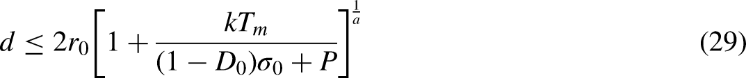
When the inclined coal seam entry is driven along the roof, the overall forming is generally trapezoid, and the entry roof has an inclination angle, as shown in the figure. In order to ensure the maximum suspension force of CRLDA and avoid the shear action on the pallet, the layout should be vertically arranged. The ordinary pallet can not adapt to the inclination angle of the roof. In order to avoid shear failure during the pretightening of the anchor cable, the wedge pallet is designed to weaken the influence of the entry roof angle on the construction of the constant resistance anchor cable, and the entry site realism and wedge pallet schematic diagram is shown in Figure 18.
Schematic diagram of CRLDA support with wedge pallet.
Gangue retaining and supporting system
During the period of dynamic pressure influence, the immediate roof will move in tandem with the subsidence of the main roof. Therefore, the gangue retaining structure should possess lateral impact resistance capabilities and exhibit deformation and pressure characteristics in the vertical direction. Considering the high-stress environment of gob-side entries in inclined coal seam mining, a high-resistance retractable gangue retaining support combination is constructed, as illustrated in Figure 19. The roof-cutting hydraulic support can provide higher active support resistance in both lateral and vertical directions, helping to mitigate roof subsidence caused by surrounding rock movement, restrict gangue extrusion in the gob, and maintain the overall stability of the bulk side along the gob.
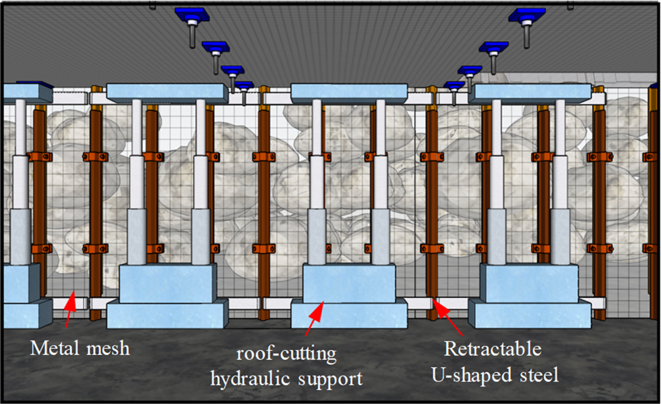
Schematic diagram of high-resistance retractable gangue retaining support.
Based on the analysis of the preceding chapters, during the mining of an inclined coal seam, the caving gangue in the goaf tends to slip and roll to the lower part of the working face. This phenomenon can have a significant impact on the gangue support in the entry. In order to mitigate the initial impact of gangue collapse, ensure the safety of on-site construction personnel, and buffer the direct impact of roof collapse gangue on the gangue retaining structure, a buffer device is designed. This device facilitates the rapid formation of a buffer cushion layer, ensuring the stability of the bulk wall side of the GEFR. The buffer device is depicted in Figure 20.
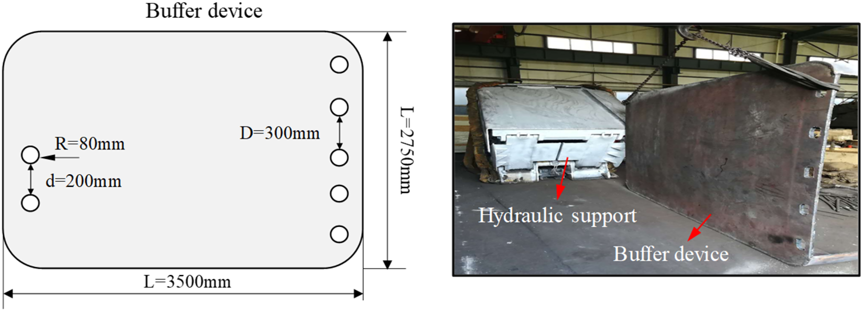
Buffer device rear of hydraulic support.
Combined-bearing temporary support system
During the initial stage of the main roof breaking and slewing subsidence, the gap between the caving gangue in the gob is large, preventing the provision of substantial supporting force to the main roof on time. As a result, it is necessary to apply temporary supporting resistance to the entry roof. This temporary support balances the mine pressure caused by the main roof’s slewing subsidence and reduces its impact on the stability of the entry surrounding rock. The temporary support system consists of single hydraulic pillars, portal supports, and roof-cutting hydraulic support. Figure 21 illustrates a schematic diagram of the various support methods.
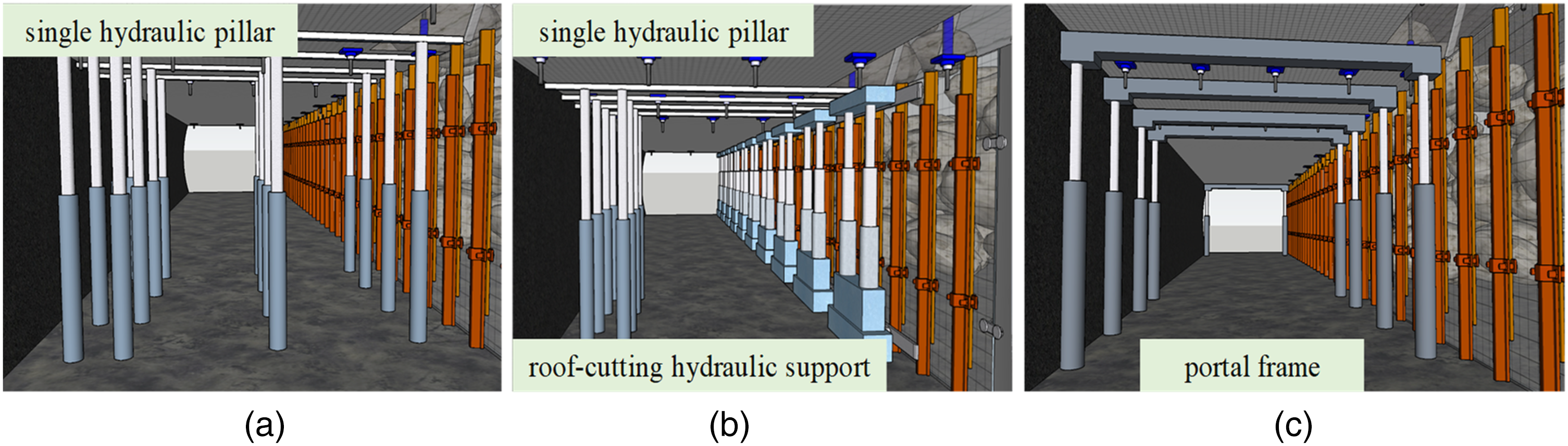
Combined-bearing temporary support technology: (a) single hydraulic pillars; (b) roof-cutting hydraulic support; (c) portal supports.
Engineering practice
Overview of test working face
The test face is buried at a depth of 215–328.9 m, has a strike length of 1025 m, and a working face length of 260 m. The dip angle of the coal seam in the mining area ranges from 12° to 32°, with an average of 22°. Coal seam thickness varies between 3.3 and 4.2 m, and the average coal thickness is 3.75 m. In this study, the area with an inclination angle exceeding 25° is chosen as the focus of the critical research.
Key parameter
According to the geological conditions of the test face and the construction requirements of the surrounding rock support system, the following design parameters have been determined:
The cutting height is 9 m, with a cutting angle of 20° and a cutting hole spacing of 500 mm. Field tests have indicated that the optimal in-hole charge structure is 44332, with a forward charge. The constant resistance anchor cable steel strand is 12.3 m, and the row distance near the cutting hole is 1000 m combined with W steel bands, the row distance in the middle of the entry is 1500 mm, and that on the coal side is 3000 mm. The support system for retaining gangue combines retractable U-shaped steel and steel mesh. The U-shaped steel is of the 29U type, with a distance of 500 mm between each unit. The structure follows a one-beam, four-column arrangement in the temporary support. The distance between single pillars near the cutting line is 800 mm, while the distance between single pillars on the opposite side is 1600 mm. The spacing between beams is 1000 mm.
The field engineering technical parameters are illustrated in the accompanying Figure 22.
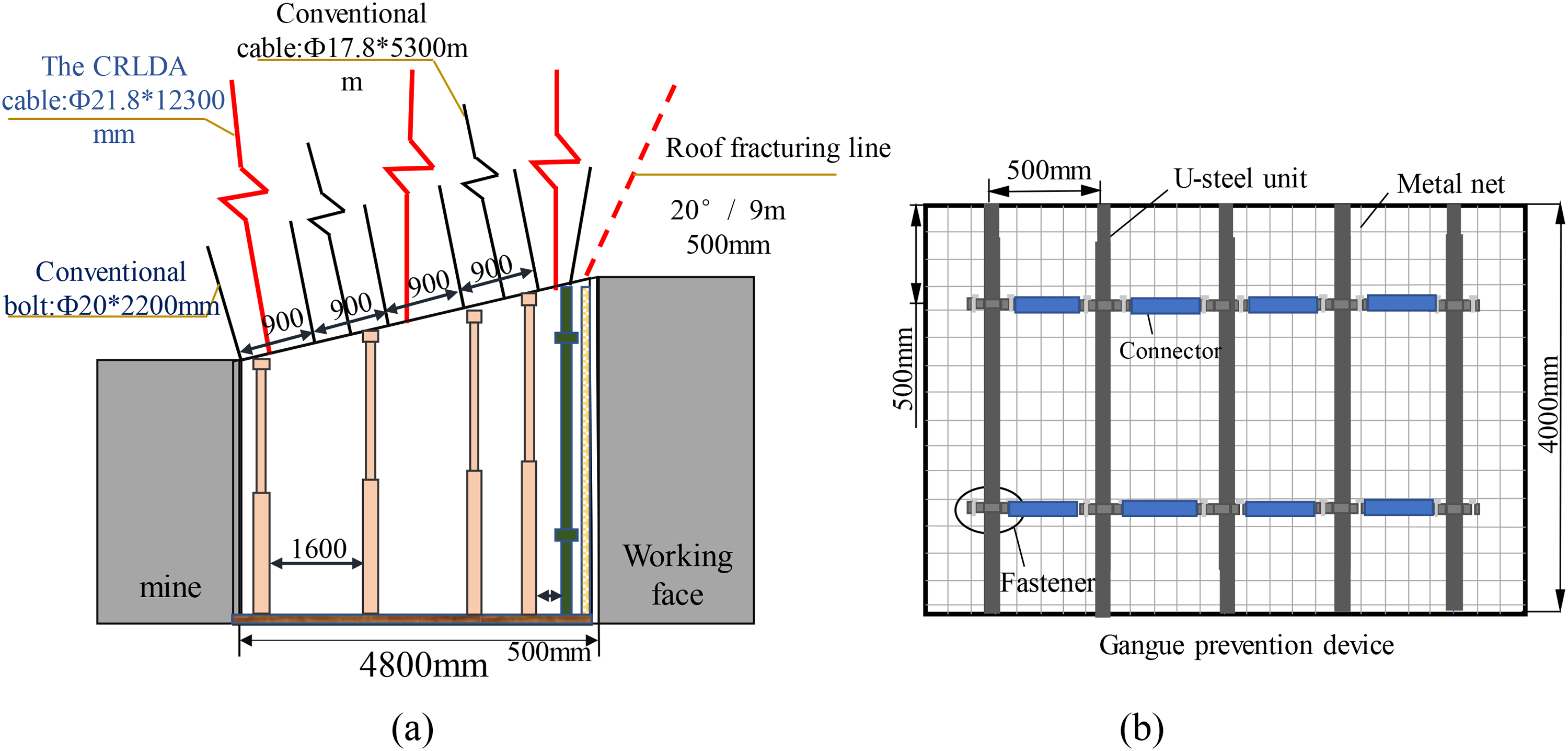
Design parameter of GEFR in the inclined coal seam: (a) parameters of support and roof cutting in entry; (b) lateral support parameters.
Tests result
In order to verify the effectiveness of GEFR technology in the inclined coal seam, several parameters are monitored, including the support pressure of the working face, the convergence of the roof and floor, and the force exerted on the constant resistance anchor cable. The monitoring layout diagram is provided in Figure 23. The stress and deformation characteristics of the surrounding rock structure in GEFR within the inclined coal seam are analyzed using the monitoring data.
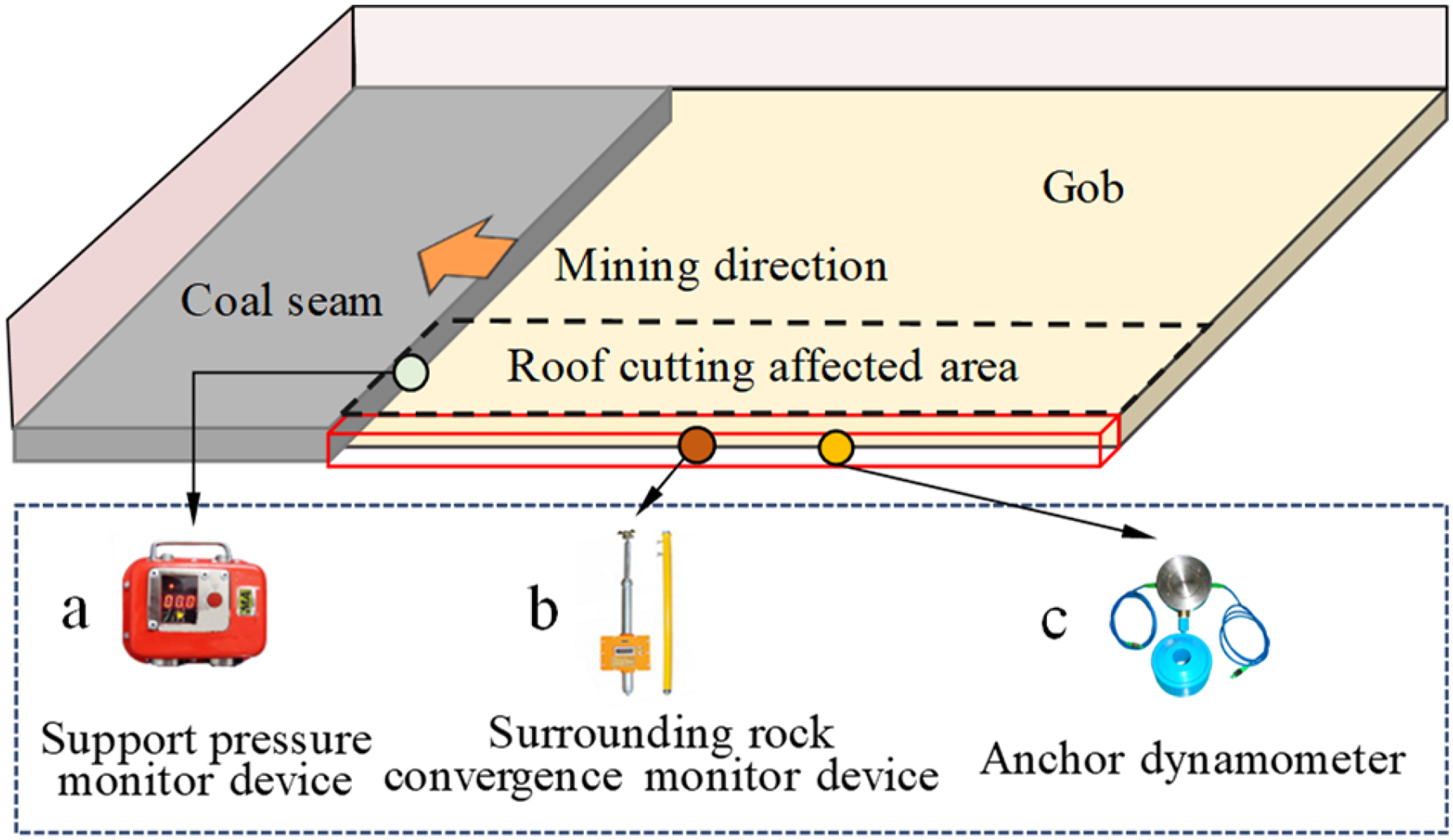
Monitoring layout diagram.
Analysis of deformation characteristics of surrounding rock in GEFR
The monitoring data from the convergence of the roof and floor at the monitoring point are extracted and organized into a variation curve, illustrating the convergence of the roof and floor as the working face advances. This curve is presented in Figure 24(a).
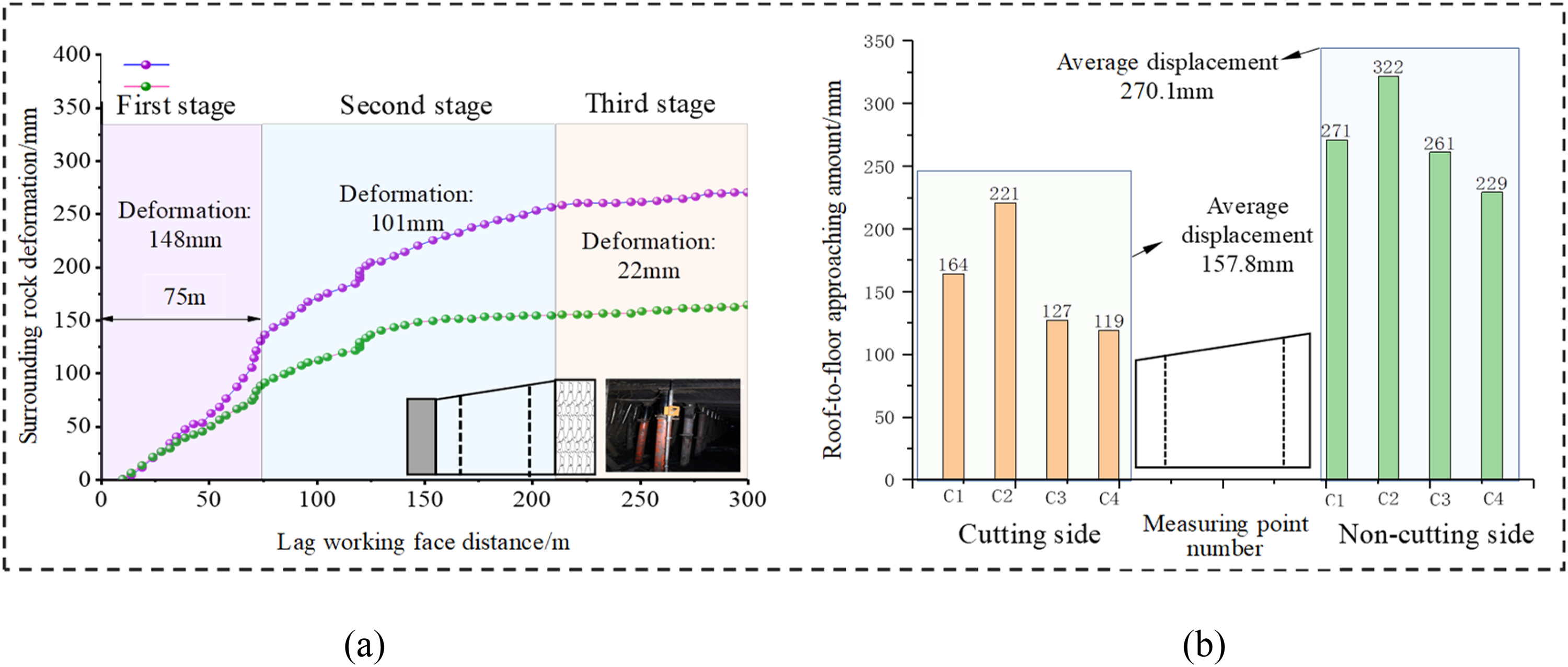
(a) The surrounding rock deformation on both the cutting and noncutting sides of the roof; (b) roof and floor convergence curve.
The variation curve of roof and floor displacement reveals that the deformation can be divided into three stages: the first stage occurs around 10–70 m behind the working face, particularly within the 40–70 m range. The roof and floor converge significantly during this stage, indicating that the main roof overlying the stope experiences severe rotary subsidence. The total deformation at the measuring point in this stage is 148 mm.
The second stage spans from 70 to 200 m behind the working face. In this stage, the convergence rate of the roof and floor decreases, suggesting that the main roof is in a slow subsidence phase and in contact with the gangue in the gob. The roof gradually stabilizes, and the total deformation at the measuring point during this stage is 101 mm.
In the third stage, which occurs 200 m or more behind the working face, the entry's support system and surrounding rock reach a balance and enter a stable phase. The total deformation at the measuring point in this stage is 22 mm.
By organizing the total convergence of the roof and floor at different measuring points, statistical charts can be generated for the surrounding rock deformation on both the cutting and noncutting sides of the roof. As illustrated in Figure 24(b), the average roof and floor displacement on the cutting side of the entry for all measuring points is 270.1 mm, with an extreme value of 322 mm. On the noncutting side, the average displacement is 157.8 mm, and the extreme value is 221 mm. The subsidence of the roof and floor on the cutting side is noticeably more extraordinary than that on the noncutting side, indicating that the roof of the GEFR exhibits asymmetric deformation.
Stress monitoring of CRLDA
The stress data from the roof anchor cables at the measuring point are extracted, and a stress change curve is generated to illustrate the variation in stress as the working face advances. This curve is presented in the accompanying Figure 25.
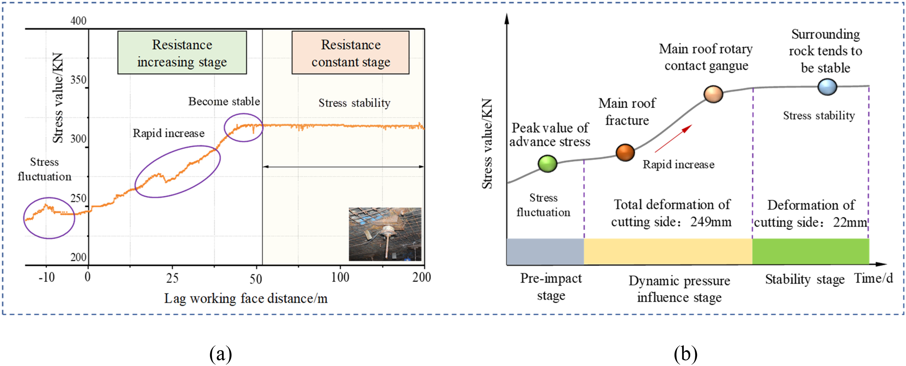
The force curve and characteristic diagram of CRLDA: (a) variation in stress as the working face advances; (b) the variation curve of roof stress with time.
The image demonstrates that the force change of CRLDA can be categorized into two stages: increasing resistance and constant resistance, as shown in Figure 25(a). The resistance-increasing stage is influenced by mining, and the concentrated stress in the working face only slightly affects the force of the anchor cable within the range of 12 m to 22 m in front of the working face. At the position of 25–40 m behind the working face, the force of the constant resistance anchor cable increases significantly, indicating the breakage of the overlying main roof strata at this stage. The force of the constant resistance anchor cable becomes stable at 45–55 m in the lagging working face and the working state shifts to the constant resistance stage.
The variation curve of roof stress with time is drawn by analyzing the anchor cable pressure, as shown in Figure 25(b). The stability of the surrounding rock structure is divided into four stages. The analysis reveals that the stress fluctuation in the leading influence stage is due to the passing of the maximum stress peak. There are two typical stress fluctuations in the dynamic pressure influence stage. Among them, the sharp increase is caused by the dynamic pressure influence of the main roof fracture, and the stress tends to become gentler because the constant resistance anchor cable starts to work after reaching the pressure relief threshold. The contact between the fractured main roof and the gangue in the stope leads to the stress change gradually transitioning to a stable stage.
Pressure monitoring of hydraulic support in the stope
For comparative analysis, two brackets have been selected, one located on the cutting side and the other on the uncut side. To facilitate the analysis of the relationship between the prop load of the hydraulic support and the weighting of the working face, the criterion for judging the weighting of the working face is when the prop load is higher than the sum of the average load and the mean square deviation, it is determined that there is a roof weighting phenomenon in the working face (Wang et al., 2020). The pressure curve is depicted in Figure 26.
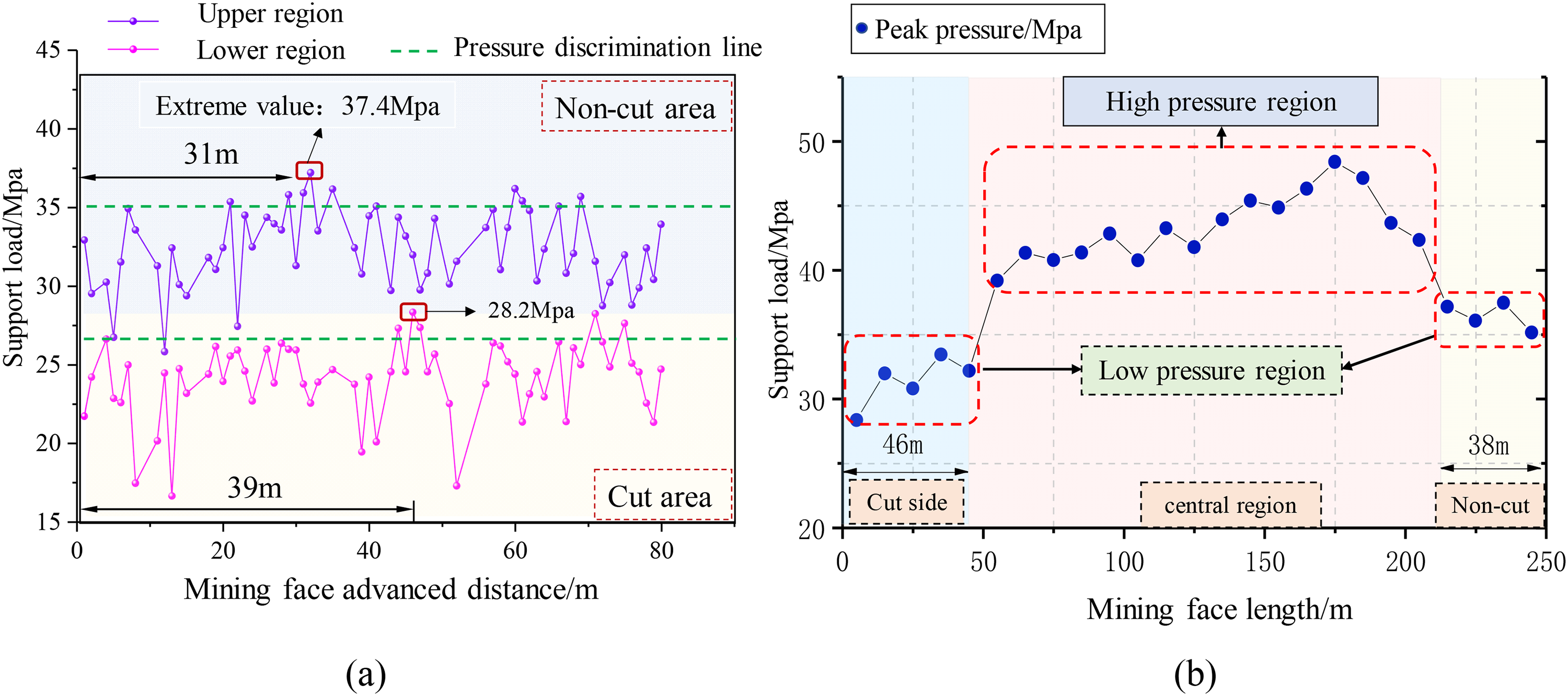
Hydraulic support load curve and peak distribution: (a) pressure curve; (b) extreme value distribution.
The load distribution map of the support shows that pressure in the slit area of the working face is not evident during the advancement of the working face, as shown in Figure 26(a). The initial weighting distance of the slotted side support is 39 m, and the maximum pillar load is 28.2 MPa, while the initial compression distance of the uncut side support is 31 m, and the maximum support load is 37.4 MPa. The working face is situated near the GEFR, and its weighting phenomenon and strength are weaker than the uncut side of the working face. This suggests that the roof gangue collapse in this area can fill the gob under the influence of roof blasting and the coal seam dip angle, and the main roof can promptly touch the gangue. Thus, it weakens the weighting strength to some extent.
The peak pressure distribution map of the initial weighting of the stope is presented in Figure 26(b). The curve distribution shows that in the nonpillar stope of the GEFR in the inclined coal seam, both the cutting and noncutting sides belong to the lower pressure area. The pressure reduction area on the cutting side is 46 m, and the noncutting side is 38 m. The average value of the pressure in the cutting seam is 32.3Mpa, which is less than the 36.8Mpa on the cutting side, and the overall pressure of the stope is asymmetrical.
In summary, the stability of the entry roof is maintained through CRLDA and control angle pressure relief combined with temporary and gangue supports, and the formation of the GEFR in the test working face is satisfactory. The section of the GEFR is stable and can meet the production demand of the next working face. The formed GEFR is illustrated in Figure 27.
Effect of GEFR in the inclined coal seam.
Discussion
This article focuses on the technical process characteristics of GEFR and divides the surrounding rock structure into two main research modules. It also categorizes the stability process of the surrounding rock into three typical stages. By conducting a mechanical analysis of the deformation characteristics for each stage in different modules, key factors affecting structural stability are identified. Corresponding control countermeasures are proposed, and successful engineering applications are demonstrated.
Module I of the studied area is thoroughly analyzed to understand the influence of changes in connection mode and load type on its strength. The results show significant variations in key deformation areas and degrees between Module I under fixed, simply supported, and cantilever states under uniformly distributed load. Three distinct instability modes are proposed, and the impact of structural integrity on stability is examined. The mechanical analysis of each mode reveals that alterations in constraint state and integrity directly affect the overall strength and stability of the structure. To address these concerns, this article proposes corresponding structural stability measures and control strategies for key control areas under varying constraints and three different instability modes.
Module II experiences an abrupt load in the initial stage and a creep load in the stable stage during stabilization. The disparity in load types significantly impacts the strength of Module II. To ensure stability during formation, it is proposed that the supporting structure of Module II should have the ability to withstand both impact and creep load. Additionally, grouting during the initial formation stage can enhance Module II's strength and bearing capacity, thus improving its overall stability. This will be the focus of future studies.
The research methodology employed in this study includes theoretical analysis and engineering testing. The theoretical analysis builds upon the work of other scholars to comprehensively explore the deformation characteristics and stability of GEFR structures in inclined coal seams. It provides a reasonable explanation for the corresponding mechanical mechanisms of these deformation characteristics. The engineering verification part uses analytical data obtained from mine pressure monitoring equipment at relevant monitoring points. The analysis process ensures that any abnormal data are removed and organized.
While this work briefly discusses the different constrained conditions of the roof structure of GEFR in inclined coal seams at three typical stages and provides the expressions of roof deflection for each stage, it does not quantitatively determine the support force required in key supporting areas. The selection of parameters for temporary support in the roadway is still based on experience. Additionally, only the roof and bulk wall of the GEFR with large deformation are selected as key modules, neglecting the influence of the deformation of the solid coal side and floor of the GEFR on the overall structure. The completeness of the research results can be further improved. Future research will focus on the deformation characteristics of the floor and solid coal side of GEFR in inclined coal seams, thus enriching the theoretical basis for the scientific selection of critical parameters of GEFR in inclined coal seams.
Conclusion
Because of the complex stress environment of nonpillar mining by GEFR in an inclined coal seam, this article provides a systematic analysis of roof stability in such a situation, proposing a mechanical criterion for GEFR roof structure instability in the inclined coal seam. The modular control countermeasures of the surrounding rock are also suggested based on the primary control factors of the stability of the surrounding rock. This article presents the following main findings:
The evolution of the roof structure of a GEFR can be divided into three forms: (a) immediate roof simple support-main roof clamped support, (b) immediate roof cantilever-main roof clamped support, and (c) immediate roof simple support-main roof simple support. The loading state of the surrounding rock of the GEFR differs at different stages, and the deformation of the surrounding rock presents noticeable sectional characteristics. The structural deformation of the surrounding rock of the GEFR can be classified into two types: stress type and structural type. Stress-type deformation is caused by the loading of rock strata, whereas structural-type deformation results from establishing a new equilibrium structure in the mining space. The GEFR roof's three types of instability modes are proposed, and the instability mechanics criteria are given accordingly. The impact energy of the gangue side is theoretically calculated, and the characteristics of the lateral supporting structure are determined. The article puts forth countermeasures of angle control pressure relief and a nonuniform coupling support system. The field test shows that the control effect on the surrounding rock of the GEFR in an inclined coal seam is satisfactory. The on-site mine pressure monitoring data indicate that the roof and floor subsidence on the slit side is significantly higher than on the nonslit side. The stress of the anchor cable can be categorized into increasing resistance and constant stages, and both the cutting side and the noncutting side belong to the area with low pressure. The pressure of the stope is asymmetric.
Footnotes
Data availability
The data used to support the findings of this research are included in the article. More information can be requested from the corresponding author.
Declaration of conflicting interests
No conflict of interest exists in the submission of this manuscript, and the manuscript is approved by all authors for publication. I would like to declare that the work described was original research that has not been published previously and is not under consideration for publication elsewhere, in whole or in part. All the authors listed have approved the manuscript that is enclosed.
Funding
The authors disclosed receipt of the following financial support for the research, authorship, and/or publication of this article: This work was supported by the Natural Science Foundation of Beijing Municipality, Natural Science Research Project of Anhui Universities, Open Project Program Foundation of Engineering Research Center of underground mine construction, Ministry of Education (Anhui University of Science and Technology), Humanities and Social Science Project of Anhui Provincial Education Department, Natural Science Research Project of Huangshan University (grant nos: 8232056, KJ2020A0317, JYBGCZX2021106, SKHS2020B01, and 2020xkjq017).