
Abstract
Triaxial hydraulic fracturing experiments were used to study the initiation pressure variation and acoustic emission characteristics of different guide seams sizes during roof hydraulic fracturing. Numerical simulations were used to explore the feasibility of multiple boreholes with prefabricated guide seams. An experiment of hydraulic fracturing on a pillar-free working face was also carried out in a coal mine. The results show that the specimens with guide seams reduced the initiation pressure, with the number of acoustic emission events and initiation pressure being inversely proportional to the size of the guide seams. Specimens without guide seams were deflected by stress and produced multi-level cracks, while the specimens with guide seams did not produce large secondary cracks and deflection. When the stress difference was small, three holes penetrated but not under large stress differences. The hydraulic fracturing technology of prefabricated longitudinal guide seams was tested in the Ningtiaota Coal Mine, and the auxiliary transportation roadway of S1201 working face was successfully retained for reuse in adjacent working faces.
Introduction
In recent years, the number of roof accidents and single fatalities dominated by rockbursts in China coal mines has been on the rise. It is necessary to adopt the cutting roof pressure relief technology to achieve stress transfer and fundamentally solve the impact of rock pressure caused by the thick and hard roof (Bacha et al., 2020; Swolkien and Szlazak, 2021; Xu et al., 2019; Zhao et al., 2018). Cutting the roof around the working face, such as cutting roadways, mining roadways on both sides, and stop lines can reduce the range and intensity of pressure and prevent large-area roof pressure from causing strong impact on personnel, roadways, and equipment. In addition, the advanced technology of pillar-free self-built roadways will also be developed in future coal mining methods. It is also necessary to cut the roof of the mining area to protect the roadway along the goaf (Liu et al., 2020; Yang et al., 2020).
In response to the demand for roof cutting and pressure relief, the blasting method has been widely applied in coal mines. The directional energy-accumulating blasting technology, the key layer determination method, and the roadway surrounding rock stress-displacement transmission mechanism have also been studied (Hu et al., 2019; Liu et al., 2019; Xue et al., 2019; Yang et al., 2019a, 2019b, 2020, 2021; Zhang et al., 2020). The “110/N00 coal mining method,” invented by Academician He Manchao, is the most representative. The “110/N00 coal mining method” is based on the “cutting cantilever beam theory,” and it can be combined with the energy-accumulating blasting technology, support design, constant resistance, and large deformation anchor cable to form a pillarless coal mining method (He et al., 2014, 2015, 2017a, 2017b, 2019). Cutting technology of shaped energy blasting is particularly advanced. The use of explosives in coal mines is increasingly restricted in China. Hydraulic fracturing has a softening effect on the roof and at the same time can form cracks, so it is the best way to replace pyrotechnics (Huang et al., 2018; Huang and Wang, 2016; Kang et al., 2018). Conventional hydraulic fracturing is affected by the crustal stress, which causes the fracture and propagation direction to be uncontrolled, and the fracture cracks and propagates in the direction of the maximum principal stress. Therefore, the directional hydraulic fracturing method is gradually applied in coal mines, such as the directional hydraulic fracturing method without guide seams. S. V. Serdyukov (2016) uses a special fracturing device to generate tension in the rock along the axis of the hole, resulting in transverse cracks. There are also hydraulic fracturing methods that use multiple boreholes to achieve directional hydraulic fracturing; for example, dense boreholes have been used to change the stress state and form free surfaces to achieve through fractures for multiple boreholes (Duan et al., 2021; Liu et al., 2019; Song et al., 2019). There are also transverse guide seam fracturing methods (Deng et al., 2016; Lin et al., 2016), longitudinal guide seam fracturing methods (Cheng et al., 2018, 2020; Ge et al., 2019; Zhong et al., 2021), guide seams, and directional hole fracturing methods (Lu and He, 2020).
In summary, various directional fracturing methods have been studied, and each method can achieve directional fracturing within a certain range. It is easy to stratify the rock during hydraulic fracturing with transverse guide seams, and it is difficult to achieve the effect of longitudinal cutting roof. The method of porous directional fracturing requires intensive borehole drilling and extensive engineering. Longitudinal guide seam fracturing has the best guiding effect, which can achieve the effect of longitudinally cutting the roof, but current research has not achieved engineering-level guiding distance. Therefore, this article proposes a method of hydraulic fracturing after cutting the longitudinal guide seams on the roof by using an abrasive water jet. The hydraulic fracturing method, shown in Figure 1, uses a conveying device to push a coiled tubing or a drill pipe with the directional abrasive water jet nozzle from the top to the bottom of the hole and uses the abrasive water jet to cut down the double-sided guide seams. The second process uses a packer to seal the guide seams of multiple boreholes and large-flow hydraulic fracturing to make the borehole penetrate in the longitudinal direction.
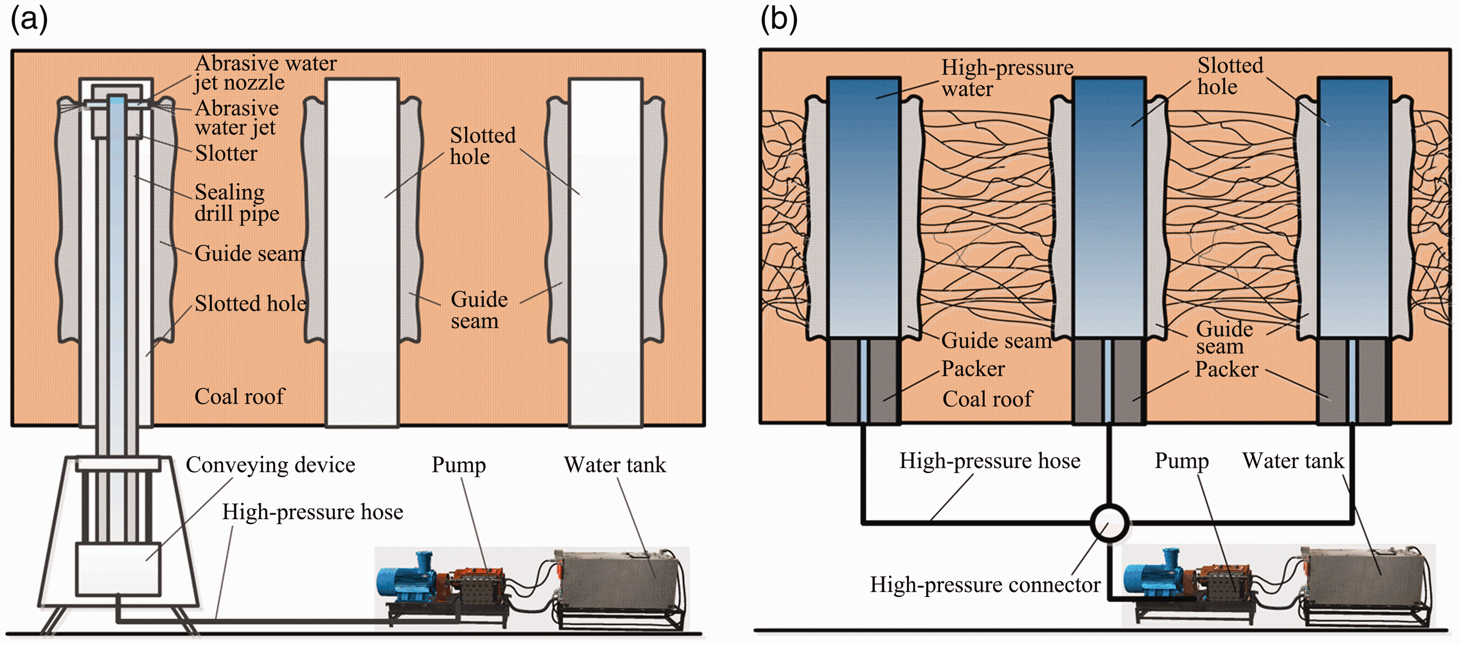
Schematic diagram of hydraulic fracturing of prefabricated longitudinal guide seams in coal roof. (a) The first process: the longitudinal guide seams are prefabricated by an abrasive water jet. (b) The second process: sealing and fracturing.
It is necessary to study the crack initiation and propagation law of fracturing after the abrasive water jet prefabricates the guide seams and the practical application effect in the coal mine to verify the feasibility of this method. First, we obtained the basic roof sandstone specimens found in underground coal mines and used an abrasive water jet to longitudinally cut double-sided guide seams. Then, hydraulic fracturing experiments under triaxial stress conditions were conducted, and the influence of longitudinal guide seams on hydraulic fracture propagation was studied. The initiation characteristics of sandstone without guide seams were assessed. Numerical simulations of hydraulic fracturing of multiple boreholes were then carried out and applied to coal mines. Other parameters, such as fracturing fluid viscosity and fracturing fluid flow rate, also affect the directional propagation distance of fractures and the deflection speed of fractures.
Fracturing test of prefabricated longitudinal guide seams in sandstone specimens
Preparation of sandstone specimens
The Ningtiaota Coal Mine is a large coal mine in Yulin City, northern Shaanxi, China (as shown in Figure 2). The coal mine has an annual output of 20 million tons per year, but its thick and hard roof restricts its development. The buried depth of the C1 coal seam is 120–200 m, but a 30-m thick layer of hard sandstone is present above the roof of the coal seam, resulting in a large periodic pressure step during the mining process. In addition, Academician He Manchao presided over the “110/N00 coal mining method” pillarless mining technology research; therefore, the prefabricated longitudinal guide joint hydraulic fracturing technology was introduced. The sandstone specimen in this experiment was taken from the S1201 working face of the Ningtiaota Coal Mine, which is also a field test working face.
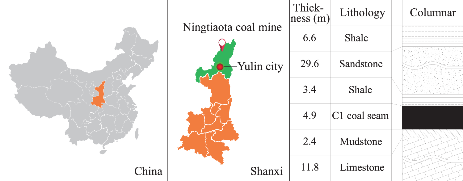
Location of the Ningtiaota coal mine and its geological occurrence of C1 coal seam.
The retrieved large blocks of sandstone were cut into cube specimens of 300 mm × 300 mm × 300 mm for hydraulic fracturing tests, and 50 mm ×100 mm standard specimens were used for triaxial compression experiments.
As shown in Figure 3, a round hole with a diameter of 20 mm and a depth of 200 mm was drilled at the center of the top surface of the cube specimen; then, an abrasive water jet bidirectional nozzle was used to cut guide slits with a length of 100 mm and at depths of 20 mm, 30 mm, and 40 mm on one side of the hole. The special fracturing seamless steel pipe was sealed with epoxy resin in the uncut section of the orifice.
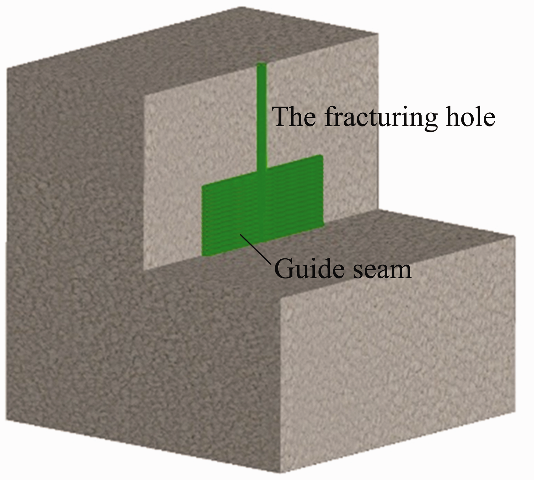
Schematic diagram of the longitudinal guide seams in the cube specimen.
Mechanical properties of sandstone
The triaxial compression test was carried out on the 50 mm × 100 mm standard specimen to explore the characteristics of a coal mine roof sandstone. The triaxial compression curve is shown in Figure 4. The uniaxial compressive strength was 131.7 MPa, the elastic modulus was 29.7 MPa, the Poisson's ratio was 0.228, the internal friction angle was 55.3°, and the cohesion was 18.6 MPa.
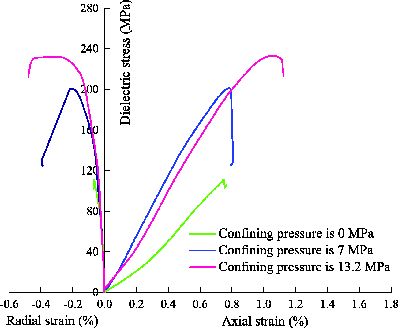
Triaxial compression curve of the sandstone specimen.
Experimental methods
The triaxial hydraulic fracturing test system shown in Figure 5 was used for hydraulic fracturing tests under triaxial stress conditions. The system consists of a pump source system, a pressure and flow monitoring system, a stress loading system, and a DISP (dimensional acoustic emission positioning) acoustic emission system. Flow and pressure changes during the experiment were measured, and acoustic emission meters were used to monitor the acoustic events at different times and locations. The method of quantitative injection of fracturing fluid was used to control the fracturing process. The flow rate was 12 L/min. The fracturing fluid was clear water, and yellow dye was added to the clear water to facilitate the observation of the fracture morphology after fracturing.
Triaxial hydraulic fracturing experimental system.
The crustal stress value was found to be too large to reduce the stress loading error and to study the relative law, but the horizontal crustal stress difference of 3 MPa was the same as that of the Ningtiaota coal mine. A maximum horizontal stress of 7 MPa was applied along the X-axis direction, a minimum horizontal stress of 10 MPa was applied along the Z-axis direction, and the simulated vertical stress applied along the Y-axis direction was 6 MPa.
Experimental results and discussion
Pressure change law during fracturing
Figure 6 shows the pressure-time curves of the sandstone specimens without guide seams and with guide seams with dimensions of 100 mm × 20 mm, 100 mm × 30 mm, and 100 mm × 40 mm, respectively. It can be seen from the figure that the longest fracturing duration of the sandstone sample without guide seams is about 67 s, and the shortest fracturing duration of the sandstone sample with guide seam size of 100 mm × 20 mm is about 52 s. During the whole fracturing process, all specimens experienced three phases: pressure accumulation, specimen initiation, and stable extension. In the pressure accumulation phase, the pipeline and the initial fracture had to be filled with water in order to reach the crack initiation pressure. In the crack initiation phase, the crack space suddenly increased and the pressure decreased. The stable extension phase involved the process of crack extension, in which the pressure was low.
Pressure curves of the sandstone specimens with different guide seams sizes.
The columnar comparison chart, Figure 7, is derived from the statistics of the initiation pressure of different specimens and the statistics of acoustic emission events. The initiation pressure of the non-guide seam specimen was about 32 MPa, while the initiation pressure of the guide seam specimens substantially decreased with the increase of the size of the guide seams, which were 70.1%, 58.5%, and 51.3%, respectively, of the non-guide seam specimen. The presence of guide seams effectively reduces the initiation pressure, helps the rock to initiate and expand, and reduces the performance requirements of the fracturing system. In addition, according to the statistics of acoustic emission events, as the size of the guide seam increases, the distance from the fracture initiation to the edge decreases, so the number of monitored acoustic emission events decreases. This law is similar to the change law of initiation pressure, that is, after reducing the initiation and fracturing, crack propagation of the rock mass is more prominent, but with fewer large fracture events. In addition, the increase in the size of the guide seam reduces the distance from the crack initiation point to the boundary of the specimen; the time for crack propagation is also shortened.
Statistical histogram of initiation pressure and acoustic emission events for different specimens.
Figure 8 shows the shape of the specimen and the spatial location of the acoustic emission event after hydraulic fracturing. After the fracturing, the sandstone specimens show brittle characteristics; they can be easily split from the cracks, and the internal morphology of the specimens can be visually observed after splitting. It can be seen from the images that the cracks of the specimens without guide seams are affected by the crustal stress and the weak surface. There is no fixed expansion surface, and the bottom of the specimens is relatively broken, which produces multi-level cracks. The cracks of the specimens with guide seams start at the tip of the guide seams. After the cracks start, they basically expand along the guide seam surface, and no major secondary cracks are produced, and no deflection occurs. The monitored acoustic emission events are consistent with the internal fracture surface expansion. The position of the acoustic emission event basically reflects the crack shape. The position near the guide seam is the crack initiation position of the specimen; therefore, when the crack just started, many acoustic emission events were monitored, and as the crack continued to expand, the acoustic emission events decreased. In the vertical view, the acoustic emission event can be seen in the area near the borehole because the top and bottom of the specimen have no guide seams and there are crack initiation characteristics.
Photos of specimens and acoustic emission results after fracturing. (a) No guide seams. (b) Guide seam size: 100 mm × 20 mm, (c) guide seam size: 100 mm × 30 mm, and (d) guide seam size: 100 mm × 40 mm.
Numerical simulation of multiple borehole directional fracturing
Numerical simulation method
Because of the small size of the simulation experiment model, the real field situation could not be fully simulated. This paper uses RFPA2D-Flow for numerical simulation to study the crack propagation law of the roof rock formation during multiple borehole fracturing and to verify the possibility of fracture conduction under different crustal stress conditions. RFPA2D-Flow is a discontinuous body deformation and fracture seepage coupling analysis software (China, Dalian), which can simulate the generation of cracks, the evolution of permeability in the process of extension and expansion, and the seepage-stress coupling mechanism, so as to simulate the occurrence of cracks; there is also a very intuitive observation of the expansion process. During the entire fracturing process, the main focus of this study was on the initiation and the final shape of the fracture. Considering the large size of the numerical model, more cell divisions, and limited software calculation capabilities, the fracturing model is considered a plane strain model. The four models use a square with a side length of 5 m × 5 m, which is divided into 250,000 cells to minimize the influence of the size on the fracturing effect. One or three round holes with a diameter of 10 mm were excavated in the middle of the model grid as fracturing holes. The distance between the two holes was 1 m, and a single-sided slot with a depth of 100 mm was prefabricated on both sides of the borehole.
The four conditions for the simulation model are as follows: No guide seam model, the guide seam is consistent with the maximum horizontal principal stress, the guide seam is perpendicular to the maximum horizontal principal stress and the stress difference is 3 MPa, and the guide seam is vertical to the maximum horizontal principal stress and the stress difference is 5 MPa. Since the numerical simulation object is the same as the experimental object, the experimental parameters were used as the source of model parameters for numerical simulation research.
Mathematical mode and parameters
A simple elastic damage constitutive model was used in RFPA2D-Flow. Before the failure criterion is reached, the element maintains the mechanical nature of linear elasticity. When the stress state of the rock meets the maximum tensile stress criterion or the Mohr-Coulomb criterion, the rock begins to fail. The mathematical model is (Li et al., 2021)

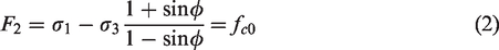

Formula (1) is the maximum tensile stress criterion. Formula (2) is the classic Mohr Coulomb criterion. Formula (3) is the damage model, where D is the damage variable, and E and E0 are the elastic moduli of the damaged and undamaged elements, respectively.
The damage variable is calculated by (Gao et al., 2019)
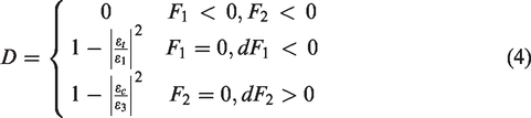
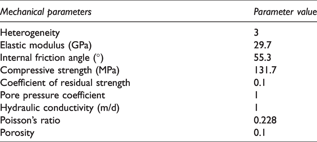
Table 1 shows the basic parameters of the model, which are derived from the experiments.
The basic mechanical parameters of models.
Model boundary conditions
After the model shown in Figure 9 was established, the boundary conditions of the model were set, mainly applying the maximum horizontal stress of 10 MPa to both sides of the above model in the form of pressure boundary conditions. Then, the minimum horizontal stresses of 7 MPa or 5 MPa were applied to the other two sides of the model in the form of pressure boundary conditions. The water injection pressure acts on the guide seam of the model. The initial water pressure was set to 5 MPa, and the injection flow rate was 120 L/min.
Numerical simulation model.
Analysis of numerical simulation results
Without guide seams
The hydraulic fracturing process of the conventional non-guide seam model is shown in Figure 10.
No guide seam model fracturing process (the stress difference was 3 MPa).
When the horizontal stress difference was 3 MPa, the cracks on both sides of the borehole cracked and propagated along the direction of the maximum principal stress because of the absence of guide seams, and secondary cracks were formed at the far end, all of which face the direction of the maximum principal stress.
Guide seam is in the same direction as the maximum horizontal stress
The fracturing process of the model with the guide fracture and the maximum horizontal stress in the same direction is shown in Figure 11. When the horizontal stress difference was 3 MPa, each borehole cracked and expanded along the tip of the guide seam. It is to be noted that the direction of the guide seam is the same as the direction of the maximum horizontal stress; thus, the cracks developed in the direction of the guide seam and continued to expand until the three boreholes penetrated the roof.
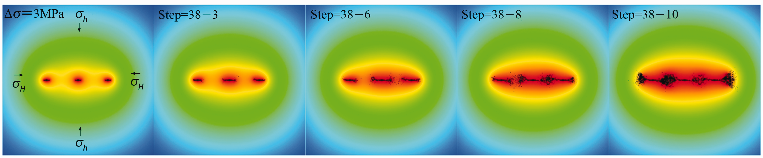
Direction of the guide seam is the same as the maximum horizontal stress (the stress difference was 3 MPa).
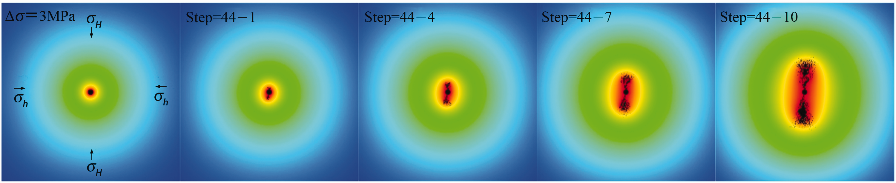
Direction of the guide seam is perpendicular to the maximum horizontal stress direction (the stress difference was 3 MPa)
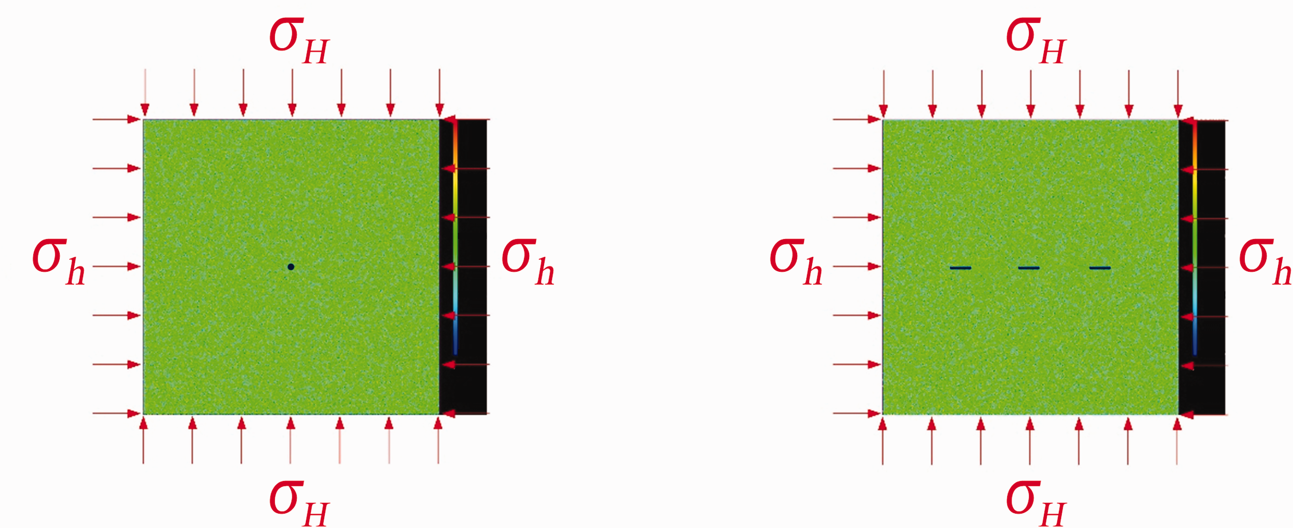
The fracturing process of the model with the direction of the guide seam perpendicular to the direction of the maximum horizontal stress is shown in Figure 12. When the horizontal stress difference was 3 MPa, each borehole cracked and expanded for a certain distance along the tip of the guide seam. Affected by the crustal stress, the cracks began to deflect towards the direction of the maximum horizontal stress after a certain distance. However, because of the interaction of cracks in adjacent boreholes, the deflection of cracks was relatively slow, but the cracks in the three boreholes were still connected. Therefore, when hydraulic fracturing is used to cut the roof in a coal mine with small crustal stress differences, directional fracturing can be used to realize multiple boreholes under the condition of small borehole spacing. Combined with the fracturing process, when the direction of the guide seam is the same as that of the maximum horizontal stress, it can be easily predicted that the fracture penetration effect is enhanced with the decrease of the angle between the direction of the guide seam and the direction of the maximum horizontal stress.
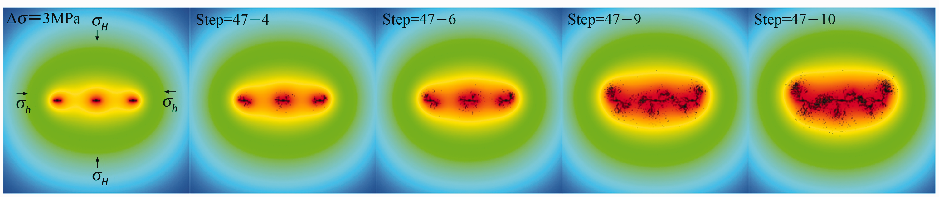
Direction of the guide seam is perpendicular to the maximum horizontal stress direction (the stress difference was 3 MPa).
Direction of the guide seam is perpendicular to the maximum horizontal stress direction (the stress difference was 5 MPa)
The hydraulic fracturing process of increasing stress difference is shown in Figure 13. When the horizontal stress difference was 5 MPa, the cracks randomly initiated at the tip of the guide seam, and after the initiation, the crack propagation direction expanded rapidly toward the direction of the maximum horizontal stress. Only few cracks expanded in the direction of the guide seams and the distance was very short; finally, no through cracks were formed. Therefore, in coal mines with a large difference in crustal stress, a large angle exists between the direction of the control roof and the direction of the maximum horizontal stress. It is difficult to control the crack initiation and propagation by using the method of guide seam, even if the borehole spacing is small.
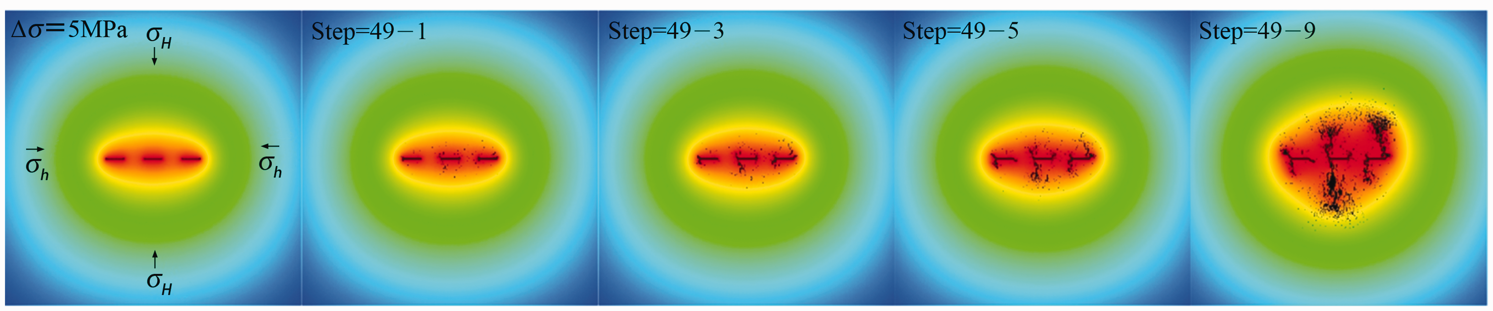
Direction of the guide seam is perpendicular to the maximum horizontal stress direction (the stress difference was 5 MPa).
As given in Formula (4), the damage variable D quantitatively describes the damage degree of the element, and the absolute value of D increases as the damage develops (Gao et al., 2019). It can be seen from Formula (3) that the value of the elasticity modulus decreases with the increase of the damage variable. Therefore, the damage state in the numerical simulation can be explained by the variation of elastic modulus. Figure 14 shows the comparison of the damaged zone and the cumulative damage area of the model in each step. When there is no guide seam, the damage area rapidly increases, and the final damage area is 0.093 m2. The final damage area after using directional fracturing is reduced by about 52% compared with the condition of no guide seam; so, the directional fracturing roof cutting technology is beneficial to maintain the integrity of the roof.
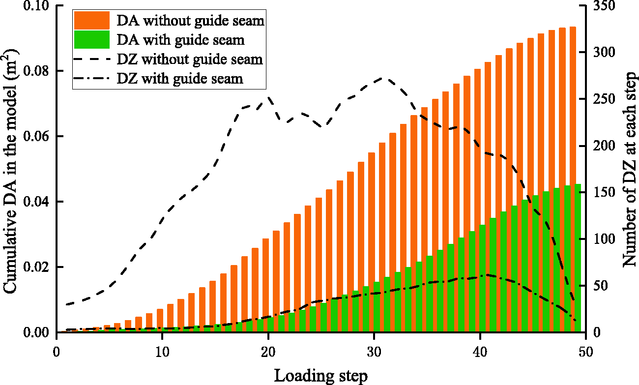
Comparison chart of the damage area (DA) and the damage zone (DZ) under two conditions.
Application
The S1201 working face of the Ningtiaota Coal Mine adopts the technology of a self-constructed roadway without coal pillar, and its technical principle is shown in Figure 15. The core is to cut the roof to reduce the stress transfer from the side of the goaf and increase the swelling volume of the roof rock mass in the goaf. Pillarless mining can be realized with the help of mine pressure and the use of broken and expanded gangue to protect the roadway. Before roof cutting, the roof of the roadway and the roof of the goaf are an integral structure, and the movement of the two is highly coordinated; after the roof is cut, the connection state of the roof structure changes. The roof rock mass in the goaf collapses along the roof cutting line under the action of periodic pressure, and the falling gangue becomes a protective roadway body. The roof of the roadway remains in its original state under the action of high-strength anchor cables with a constant resistance and a large deformation. Since the roof of the roadway is transformed from the long-arm rock beam to the short-arm rock beam after the roof cut is taken, the cantilever load transmission is reduced to a certain extent, which is beneficial to the stability of the roadway. The original design of the roadway used the blasting method to cut the roof, but owing to government restrictions on the use of explosives, the directional hydraulic fracturing technology was introduced to cut the roof.
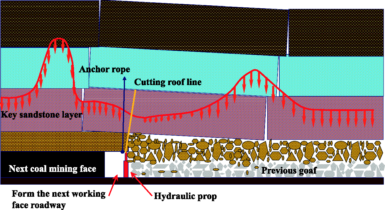
Technical principle of self-built roadway without coal pillar.
The hydraulic fracturing process of prefabricated longitudinal guide seams is shown in Figure 16. The whole set of test equipment includes a fracturing pump, an abrasive tank, a pressure regulating device with coiled tubing and a conveying device, a cutting nozzle, and a dual packer. Part of the equipment is installed in the customized equipment protection room behind the end of the hydraulic support to prevent accidental injuries from falling rocks on the roof. With the advancement of the working face, after constructing hydraulic fracturing holes with an inclination of 12° at a distance of 1 m, we first installed a double-sided abrasive water jet cutting nozzle on the top of the coiled tubing. Three sections of longitudinal guide seams on both sides as shown in Figure 17 were cut out at every interval of the borehole; the length of the guide seam was 4 m, and the depth of the single side guide seam was 100 mm. We then installed dual packers at both ends of the guide joint and connected the coiled tubing to carry out drag-type segmented hydraulic fracturing.
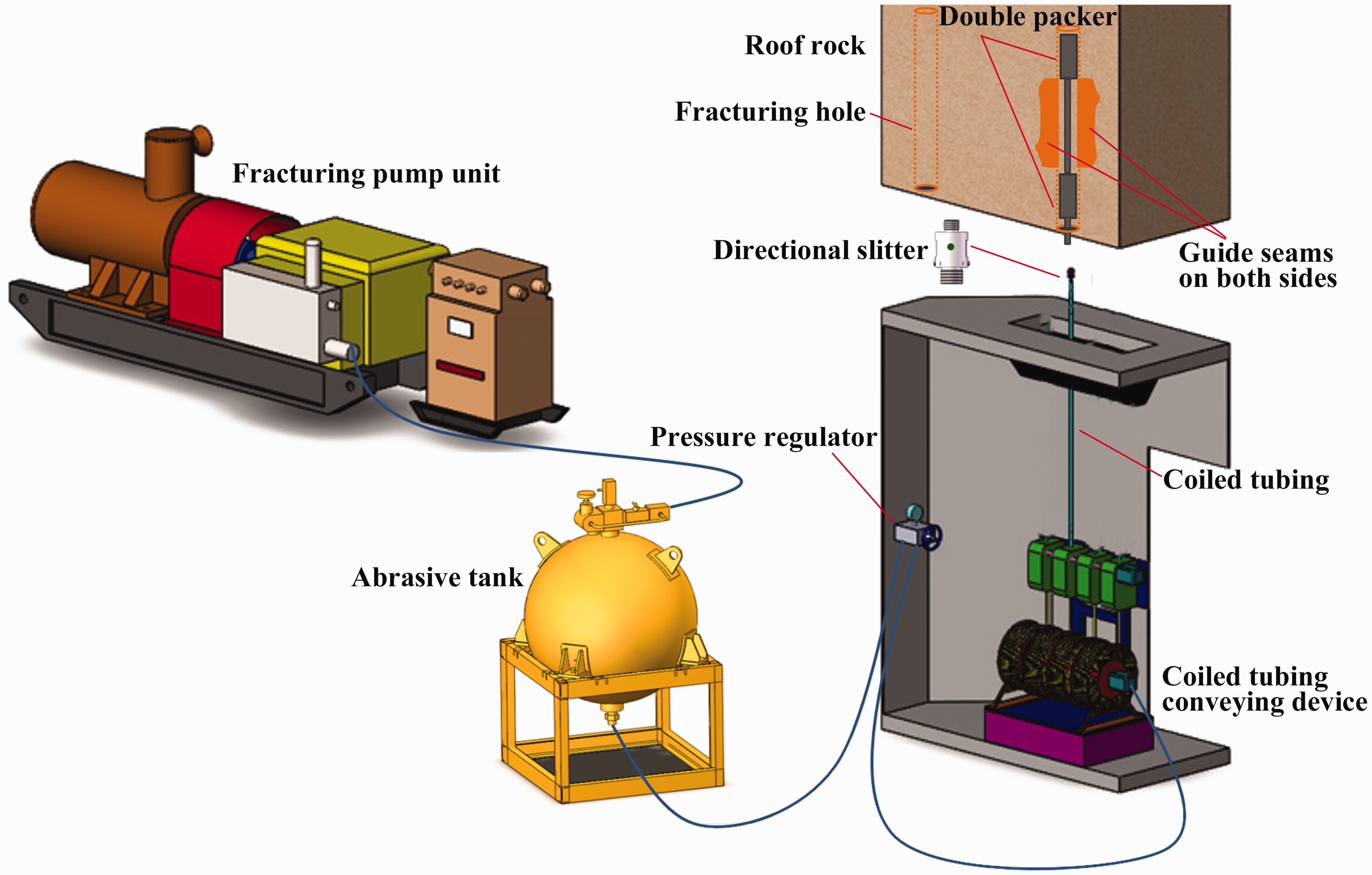
Prefabricated longitudinal guide joint hydraulic fracturing technology.
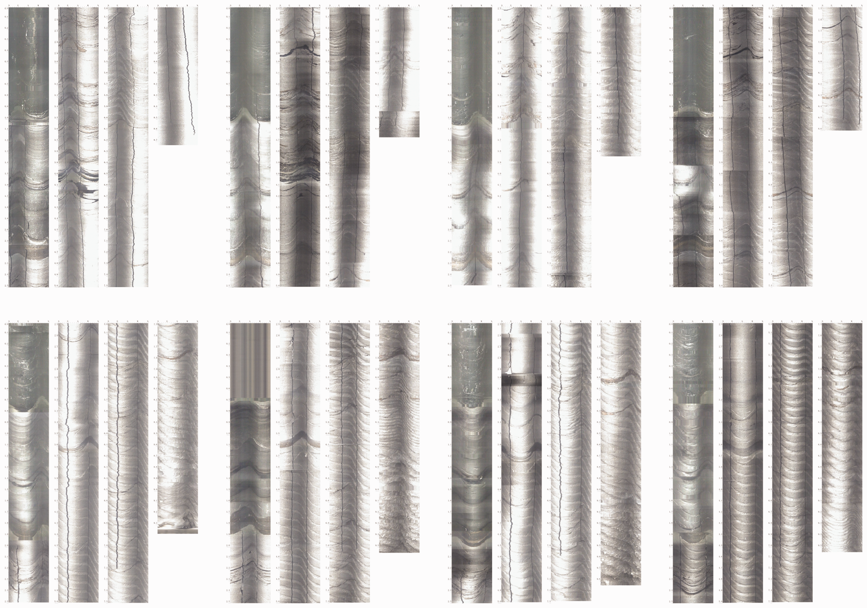
Shape of the guide seam after cutting by abrasive water jet in borehole.
A total of 231 roof cutting boreholes were constructed within 240 m along the direction of the working face, of which 109 boreholes were hydraulically fractured. The maximum initiation pressure of the boreholes was 58 MPa, and the maximum pressure drop after the initiation was 19.2 MPa. The sound of rock fracture could be heard during the fracturing of most of the boreholes, and water was produced from both sides of the borehole. The time range from the start of fracturing to penetration was 18–42 min, indicating that fracturing penetration was achieved through the guide seam within this distance, and the effect of forming the predetermined roof cutting line penetration was achieved. In the process of retaining the roadway, the cross-measuring point method was used to monitor the approach amount of the roof and the floor of the roadway and the approach amount of the two sides. According to the monitoring results shown in Figure 18, the final deformation of the floor heave of the retaining roadway was 88 mm, the final deformation of the roof subsidence was 173 mm, and the final convergence between the roof and the floor was 261 mm. Convergence on both sides in the early stage was mainly manifested as the sideward movement of gangue, and the convergence on both sides in the later period was mainly manifested as the sideways movement of solid coal. The final deformation on the gangue side was 63 mm, the final deformation on the solid coal side was 127 mm, and the final convergence on both sides was 190 mm. The figure shows the characteristics of different stages of deformation of the roof, floor, and both sides. The deformation of the roof and floor was faster than the deformation on both sides, but at the end, they tended to be stable, and there was no major secondary impact deformation.
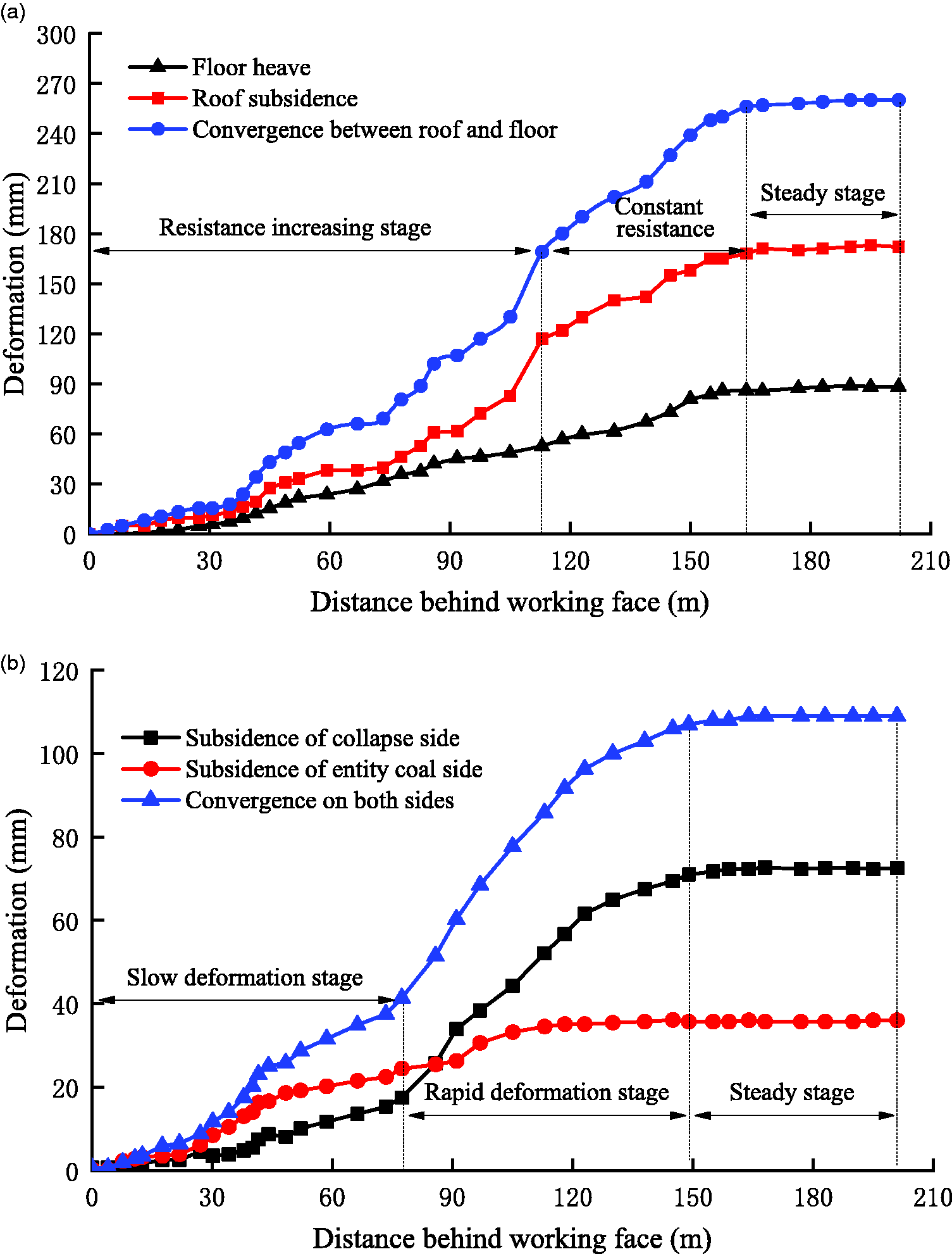
Monitoring curve of the convergence of the roof, floor, and both sides. (a) Convergence between roof and floor. (b) Convergence on both sides.
Through hydraulic fracturing and other auxiliary measures, the Ningtiaota Coal Mine successfully retained the auxiliary transport roadway of the S1201 working face for reuse in adjacent working faces.
Conclusions
The pressure characteristics of the triaxial hydraulic fracturing test are relatively simple. The initiation pressure of the specimen is inversely proportional to the size of the guide seam. A larger guide seam size corresponds to a lower initiation pressure. The initiation pressure of the specimens with a guide seam is at least 29.6% lower than that for specimens without a guide seam. The characteristics of the acoustic emission quantity of the triaxial hydraulic fracturing test are consistent with the characteristics of the fracture initiation pressure, and the acoustic emission quantity is inversely proportional to the size of the guide seam. The acoustic emission signal distribution of the specimen with a guide seam is basically linear, which is consistent with the crack direction of the specimen after the specimen is split, while the cracks of the specimen without a guide seam form deflection cracks and secondary cracks, and the acoustic emission signal distribution is relatively random. Numerical simulation results verify the possibility of fracturing hole connectivity when the horizontal stress difference is small. When the horizontal stress difference was 3 MPa, the cracks started from the guide seam and slowly deflected, and the cracks of the three boreholes with a spacing of 1 m were penetrated. When the horizontal stress difference was 5 MPa, the cracks started at the guide seam but quickly deflected and propagated toward the direction of the maximum horizontal principal stress, failing to form connected cracks. The hydraulic fracturing technology of prefabricated longitudinal guide seams was applied in the field test in the Ningtiaota Coal Mine of Shaanxi Province instead of explosive blasting. The Ningtiaota Coal Mine successfully retained the auxiliary transport roadway of the S1201 working face for reuse in adjacent working faces. After roof-cutting measures were taken, the deformation of the roof and floor and both sides finally stabilized, because the stress transmission was reduced, and there was no secondary impact and large deformations.
Supplemental Material
sj-pdf-1-eea-10.1177_01445987211028997 - Supplemental material for Directional hydraulic fracturing technology for prefabricated longitudinal guide seams in a coal mine tight sandstone roof
Supplemental material, sj-pdf-1-eea-10.1177_01445987211028997 for Directional hydraulic fracturing technology for prefabricated longitudinal guide seams in a coal mine tight sandstone roof by Liangwei Li and Wenbin Wu in Energy Exploration & Exploitation
Footnotes
Acknowledgments
The authors gratefully acknowledge the helpful comments and suggestions of the reviewers, which have improved the document.
Declaration of conflicting interests
The author(s) declared no potential conflicts of interest with respect to the research, authorship, and/or publication of this article.
Funding
The author(s) disclosed receipt of the following financial support for the research, authorship, and/or publication of this article: This paper was partially supported by Major Scientific and Technological Innovation Projects in Shandong Province (2019SDZY02) and National Science and Technology Major Projects (2016ZX05045004002).
References
Supplementary Material
Please find the following supplemental material available below.
For Open Access articles published under a Creative Commons License, all supplemental material carries the same license as the article it is associated with.
For non-Open Access articles published, all supplemental material carries a non-exclusive license, and permission requests for re-use of supplemental material or any part of supplemental material shall be sent directly to the copyright owner as specified in the copyright notice associated with the article.