
Abstract
Based on 7135 working face of Qidong Coal Mine, the cracking mechanism of pre-splitting of gob-side entry retaining by roof cutting and the key parameters of pre-splitting blasting are studied by means of theoretical analysis, numerical simulation, and on-site measurement. Under the same blasting conditions, the energy of shaped-charge blasting in the direction of shaped charge is much larger than that of non-shaped-charge blasting, and the cracks generated along the direction of shaped charge are longer than that of non-shaped-charge blasting. The key parameters of pre-splitting cracks are the hole spacing and charge length. The crack propagation law of two holes blasting at the same time with different blasting methods, different linear charge density, and different hole spacing is studied. It is obtained that the cracking effect of shaped-charge blasting with the same hole spacing is better than that of non-shaped-charge blasting, showing that it can form part-through cracks; Increasing the linear charge density can increase the crack distance, but also destroy the integrity of the retained rock mass. The key parameters of advanced pre-splitting blasting in engineering practice are put forward. Generally, the maximum hole spacing and the minimum charge length that can produce part-through cracks are selected. When the hole spacing is 600 mm and the charge length is 4 m, the crack propagation of roof and the stress change of anchor cable after blasting are measured, and the crack formation rate reaches 86% to 90% within the blasting depth of blasting hole, and the anchor cable is in a good stress state, which can effectively control the roof. The research results provide a theoretical basis for the parameter design of pre-splitting blasting cracking of gob-side entry retaining by roof cutting.
Keywords
Introduction
Gob-side entry retaining by roof cutting is to weaken or cut off the stress transfer between the roadway roof and the gob roof through pre-splitting blasting on the side of the gob of the roadway roof. After mining the working face, the gob roof collapses and it is filled by using the crack-expansion characteristics of collapsed gangue, so as to realize the automatic roadway formation without coal pillars and no roadside filling (Manchao, 2023). Therefore, it is the prerequisite and key to the successful implementation of gob-side entry retaining by roof cutting to form a continuous and effective cutting surface (Hui et al., 2023). In the process of cracking rock mass by pre-splitting blasting of gob-side entry retaining by roof cutting, it is necessary to ensure the formation of an effective cutting surface and the stability of the retained rock mass.
In terms of cracking rock mass caused by pre-splitting blasting, Hongda et al. (2020) think that after shaped-charge blasting, the fracturing of shock wave on the rock in the set direction, the tensile of stress wave on the rock in the set direction to form initial cracks, and the crack propagation caused by the joint action of high-temperature and high-pressure gas wedge and tensile force. Di et al. (2023) proposed the use of pre-grooving and multi-point shaped charge jet to impact the rock for guiding and propagating cracks to realize directional splitting of rock. Kaifei et al. (2023) put forward that the dynamic action of shaped-charge blasting is dominant on the initiation and initial propagation of cracks, while the static action of blasting gas is dominant on the later propagation of cracks. Bo et al. (2021) believed that the stress wave along the direction of the shaped charge will further expand the crushing groove and produce initial cracks, and then the blasting gas and the stress wave will work together to further stretch the cracks in the direction of the shaped charge. Aiming at the double-hole shaped-charge blasting, De yong et al. (2020) believed that the superposition of stress waves caused the formation of uniform pressure zone in part of the middle section of the two blasting holes and in the adjacent areas, which dominated the formation of the blank zone of blasting-induced cracks. Kui et al. (2019) believed that the initial guide crack generated in the direction of shaped charge is much larger than other fine cracks, and the high-pressure blasting gas enters the initial guided crack and extends the initial crack. Lexin et al. (2023) and Wei et al. (2022) conducted rock loading tests with different rock types and studied the mechanism of Type I crack propagation under the influence of rock types. The formation mechanism of macroscopic fracture surfaces of different types of rocks was analyzed, and the influence mechanism of lateral pressure on the mechanical behavior of different types of rocks was obtained. In recent years, domestic scholars have also carried out many studies on carbon dioxide phase transition cracking rock masses. Yong et al. (2024) and Shaobo et al. (2023) concluded that the liquid carbon dioxide phase transition impacted the borehole wall, and the borehole wall produced initial cracks under the action of stress waves, and the high-pressure carbon dioxide gas further expands the initial cracks. Shaobin et al. (2023) and Weiguo et al. (2022) believed that the supercritical CO2 thermal shock cracking process mainly consists of the initial stage in which the transient release of high-pressure gas produces stress wave-induced radial cracks, and the phase transition expansion stage in which high-temperature and high-pressure CO2 drives the expansion of radial dominant cracks and the formation of branch cracks.
Aiming at the key parameters of pre-splitting cracking, Yubing et al. (2019) proposed the directional tensile blasting cracking technology based on the fact that the pre-splitting operation should not only ensure the roof to be “cut open,” but also ensure that the integrity of the roadway roof cannot be damaged. Xinzhu et al. (2020) believed that the pre-splitting blasting of gob-side entry retaining by roof cutting should ensure the roof cracking along the direction of the hole connection and the stability of the roadway roof. Considering the dynamic and static coupling action of the roof during the pre-splitting blasting, the mechanism of basic roof cracking and stability criteria were studied, and the parameters of hole spacing and charge weight of shaped-charge blasting were calculated. Shang yuan et al. (2019) comprehensively studied the influence of the parameters of shaped-charge blasting hole spacing and charge weight on roof cracking, and determined the shaped-charge blasting hole spacing and charge weight to form directional cracks. Qi et al. (2023) realized the controlled blasting of directional fracture of rock through the bio-directional shaped-charge device, established the mechanical model of the bio-directional shaped-charge tensile blasting, and used the bio-directional shaped-charge device to generate concentrated tensile stress on the hole wall, so as to realize the directional fracture of rock mass and reduce the damage to the surrounding rock. Manchao et al. (2018) summarized that pre-splitting of advanced roof is the key process for no-pillar mining with gob-entry retaining, and proposed the shaped-charge blasting technology with deep and shallow hole coupling, the multi-row shaped-charge hole blasting method, etc. for different roof conditions; Aiming at the phenomenon of nonlinear large deformation presented by the surrounding rock of the deep mining roadway, the key parameters of gob-side entry retaining by roof cutting are comprehensively determined, and the remarkable engineering verification effect have been obtained.
In summary, the initial cracks occur in rock mass under the action of blasting stress wave, and the joint action of stress wave and blasting gas wedge aggravates the crack propagation, resulting in cracking or fracture of rock mass. The pre-splitting cracking of gob-side entry retaining by roof cutting should ensure that the roadway roof and the gob can be broken, but ensure the integrity of the retained rock mass. Based on the 7135 working face of Qidong Coal Mine, the author studies the cracking mechanism and crack propagation law of advanced pre-splitting blasting, and the research results provide a theoretical basis for the parameter design of advanced pre-splitting blasting of gob-side entry retaining by roof cutting.
Analysis of cracking mechanism of advanced pre-splitting blasting of gob-side entry retaining by roof cutting
Project overview
The 7135 working face of Qidong Coal Mine is the DF5-21 fault protection coal pillar in the east, the transportation uphill of the 71 coal No. 3 mining area in the west, the 7133 planned working face in the south, and the 7137 working face that has been mined in the north. The elevations of the working face are from −482 m to −565 m, the dip length is 175 m, the strike length is 1688 m, the average thickness of the coal seam in the working face is m = 3.3 m, the width of the roadway is b = 5.0 m, the height is h = 3.0 m, and the average dip angle of the coal seam is 12°. Above the working face is the old empty area of 6133 working face, and the normal distance is about 39 m. The average burial depth is 520 m, and the maximum burial depth is 582 m. According to reference (Heping et al., 2015) the maximum burial depth of the working face is at the critical depth, as shown in Figure 1.
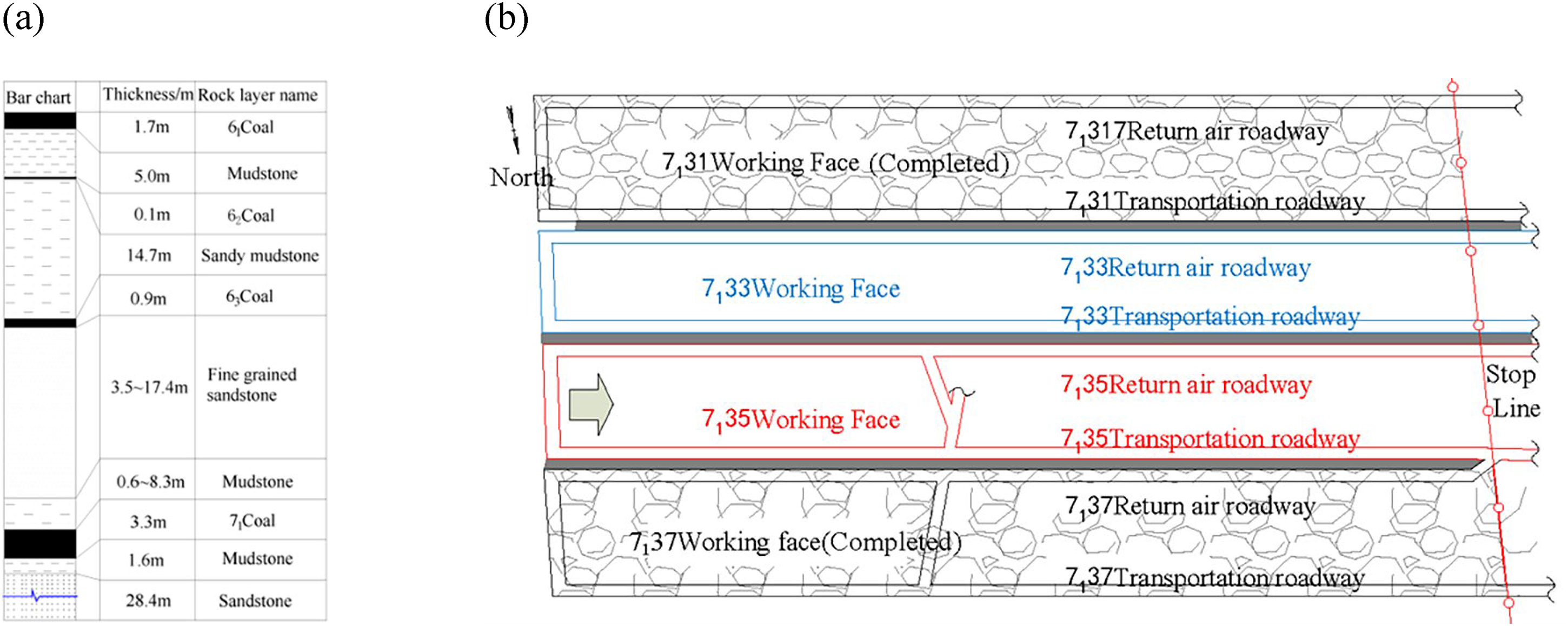
Roadway layout and geologic histogram of working face: (a) geologic histogram and (b) roadway layout plan.
Roof of the working face: From the open-off cut to the stop-mining position of the working face, the thickness of the immediate roof strata varies from 0.6 m to 8.3 m and the lithology is mudstone, while the thickness of the main roof varies from 3.5 m to 17.4 m and the lithology is fine sandstone. The average thickness of the immediate roof is 3.0 m, and the average thickness of the main roof is 6.2 m. Bottom of the working face: The direct bottom is mudstone with an average thickness of 2 m, and the basic bottom is fine sandstone and medium sandstone with an average thickness of 28 m.
Analysis of cracking mechanism of pre-splitting blasting of gob-side entry retaining by roof cutting
When the stress wave produced by pre-splitting blasting is transferred from the hole wall to the deep within the rock mass, due to the different wave impedance on the free surface, it forms a reverse tensile stress wave, which will produce tensile stress on the rock mass, but the tensile strength of the rock mass is far lower than its compressive strength. When the tensile stress exceeds the tensile strength of the rock mass, the rock mass will produce cracks. Blasting gas aggravates the crack propagation, resulting in rock mass fracture (Bo et al., 2021; Qiuyu et al., 2016). Stress wave superposition is the main cracking factor in shaped-charge blasting. The stress wave attenuates continuously in the process of propagating around the hole wall, and the action energy in the shaped-charge direction is much larger than that in the non-shaped-charge direction. Taking the shaped-charge direction as the research object, according to the attenuation formula and wave theory of stress wave with distance in the rock mass, the maximum tensile stress tangential to the connection of holes is obtained, with the establishment of rock tensile strength as the critical indicator of the cracking condition, so as to determine the minimum charge length for different hole spacing.
For ordinary blasting holes with radial and axial uncoupled charges, the peak blasting load on the hole wall can be expressed as:
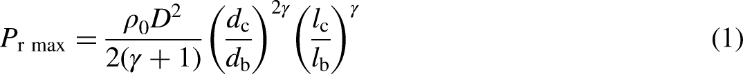
The energy attenuation occurs when stress wave propagates in rock mass, and the peak value of radial stress will decrease continuously. The relationship between the peak value of radial stress and the attenuation of distance can be expressed as follows:
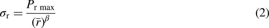
The tangential tensile stress σθ produced by the single hole initiation stress wave in the rock mass can be expressed as:


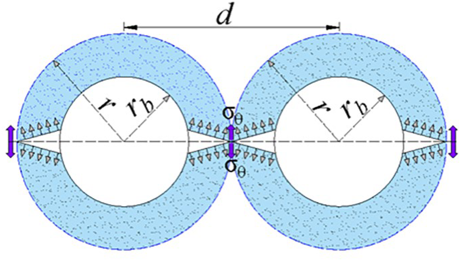
Mechanical model of double shaped-charge blasting holes.
When there is an angle between the blasting hole and the roof of the rock strata, Formula (4) can be expressed as:


Study on key parameters of cracking of gob-side entry retaining by roof cutting
Modeling
From Formula (7), it can be seen that the hole spacing and the length of charge, that is, the charge weight, are the key parameters that affect the cracking of gob-side entry retaining by roof cutting. If the hole spacing is too small or the length of charge is too long, the blasting energy will be too large, which will lead to the crushing of rocks around the holes, so as to affect the integrity of the roadway roof and be not conducive to the maintenance of the roof. On the contrary, it will fail to form part-through cracks between the holes, with poor effect of cracking.
In order to obtain the crack propagation law of rock mass under the conditions of different pre-splitting blasting parameters, the roof crack propagation law during the advanced pre-splitting blasting under the conditions of shaped-charge blasting, non-shaped-charge blasting, different linear charge density, and different hole spacing was studied by numerical simulation based on the engineering background of the return airway of 7135 working face in Qidong Coal Mine. The length of charge cannot be represented in the plane numerical simulation, and a feasible solution is to change the linear charge density (Junhua et al., 2016). The established calculation model is shown in Figure 3, in which the medium material around the hole composes of rock, uncoupled space, air, PVC pipe, and explosives, respectively.
Medium material around blast hole.
For the material meson involved in numerical analysis, the coupling relationship between fluids and solids is dealt with ALE method. Since the rock under blasting action has the characteristics of large deformation and high strain rate, the kinematic model is selected to simulate the dynamic response of rock mass under the blasting environment. The material parameters of rock mass are shown in Table 1.
Rock mass material and joint fracture material parameters.
In order to accurately simulate the effect of blasting crack, it is also necessary to give the JWL equation of state of the explosive, the expression of which is shown in Formula (8).
Explosive parameters.
Law of crack propagation under different conditions
Crack propagation with different hole spacing
In order to obtain the law of crack propagation between holes under the condition of different hole spacing and to measure the effect of roof cracking, the blasting mode is set as shaped-charge blasting, and the parameters of crack propagation law of plane simulated blasting are selected as follows: the linear charge density is selected as 1.1 g·cm−1, and the hole spacing is, respectively, 400 mm, 600 mm, and 800 mm. The law of crack propagation between holes is as shown in Figures 4–6.
Crack propagation with hole spacing of 400 mm: (a) 37.5 μs; (b) 75 μs; (c) 87 μs; (d) 100 μs.
Crack propagation with hole spacing of 600 mm: (a) 37.4 μs; (b) 212.4 μs; (c) 287 μs; (d) 300 μs.
Crack propagation with hole spacing of 800 mm: (a) 50 μs; (b) 100 μs; (c) 200 μs; (d) 400 μs.
When the hole spacing is 400 mm and 600 mm, respectively, the crack propagates linearly along the direction of shaped charge after the explosion, and there is stress concentration at the tip of the crack. When the spacing between two holes is 100 μs and 300 μs, respectively, a part-through crack is formed between the two holes. When the hole spacing is 800 mm, the explosion occurs 400 μs, and the crack propagates along the connecting line of the two holes, but due to the energy dissipation, the part-through crack cannot be formed between the holes. The blasting crack propagation is linear in the direction of shaped charge, and no crack propagation around the hole in the direction of non-shaped charge. Therefore, the pre-splitting blasting can achieve the effect of cracking when the hole spacing is 400 mm and 600 mm, respectively, while the hole spacing is 800 mm, the roof cannot form part-through cracks along the roof-cutting line.
Laws of crack propagation in different blasting methods
In engineering practices, the maximum hole spacing which can achieve the effect of cracking is taken as the blasting parameter. In order to obtain the law of crack propagation between shaped-charge blasting and non-shaped-charge blasting, when the hole spacing is set at 600 mm with the use of non-shaped-charge blasting, the crack propagation is shown in Figure 7.
Crack propagation in ordinary blasting: (a) 100 μs; (b) 200 μs; (c) 300 μs; (d) 400 μs.
The explosion occurs for 100 μs to 400 μs, and the cracks around the hole propagate in double “X” shape along the hole connection line and the vertical connection line. The vertical hole connection line cracks are easy to destroy the integrity of the roof, which is not conducive to the roof control. At 400 μs after blasting, the non-shaped-charge blasting makes the explosion energy dissipate in the direction of the retained rock mass, and the part-through cracks cannot be formed between the hole connection lines. Comparing with Figures 5 and 7, the research shows that under the conditions of the same charge line density and hole spacing, the shaped-charge blasting can effectively cause the part-through cracks in the hole connection lines, and ensure the integrity of the retained rock mass.
The crack propagation law of different charge density
When the charge density is used to characterize the length of the charge, the hole spacing is at 600 mm, and the charge density increases to 1.5 g·cm−1, the crack propagation in the hole is shown in Figure 8. When the explosion occurs at 100 μs, the crack propagation in the retained rock mass is obvious. When the explosion occurs at 137 μs, a part-through crack is formed between the two holes, but the failure crack in the retained rock mass is also produced. In the case of roof cutting by advanced pre-splitting blasting, under the same hole spacing, increasing the charge density can achieve the effect of cutting, but at the same time, it will destroy the integrity of the roof. Therefore, in engineering practices, the minimum charge length can be selected to realize the cracking of the roof.
Crack propagation with increasing charge density: (a) 50 μs; (b) 100 μs; (c) 124 μs; (d) 137 μs.
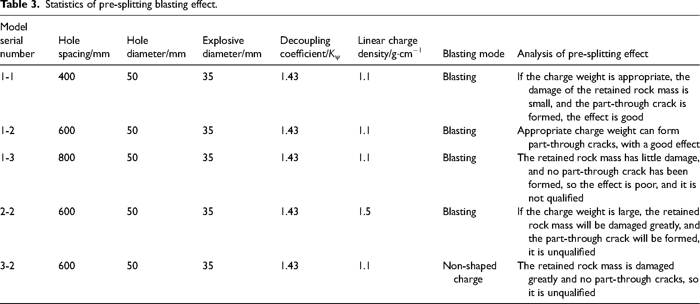
The blasting effects under different hole spacing, blasting mode, and charge density are statistically compared and analyzed, and the results shown in Table 3 are obtained. Shaped-charge blasting is an effective way to achieve pre-splitting roof crack, and the hole spacing and the length of charge are the key parameters to realize the opening of roof and ensure the integrity of roadway roof.
Statistics of pre-splitting blasting effect.
Distribution of blasting stress in different hole spacing
The stress at the midpoint of two holes in shaped-charge blasting with different hole spacing is monitored, as shown in Figure 9.
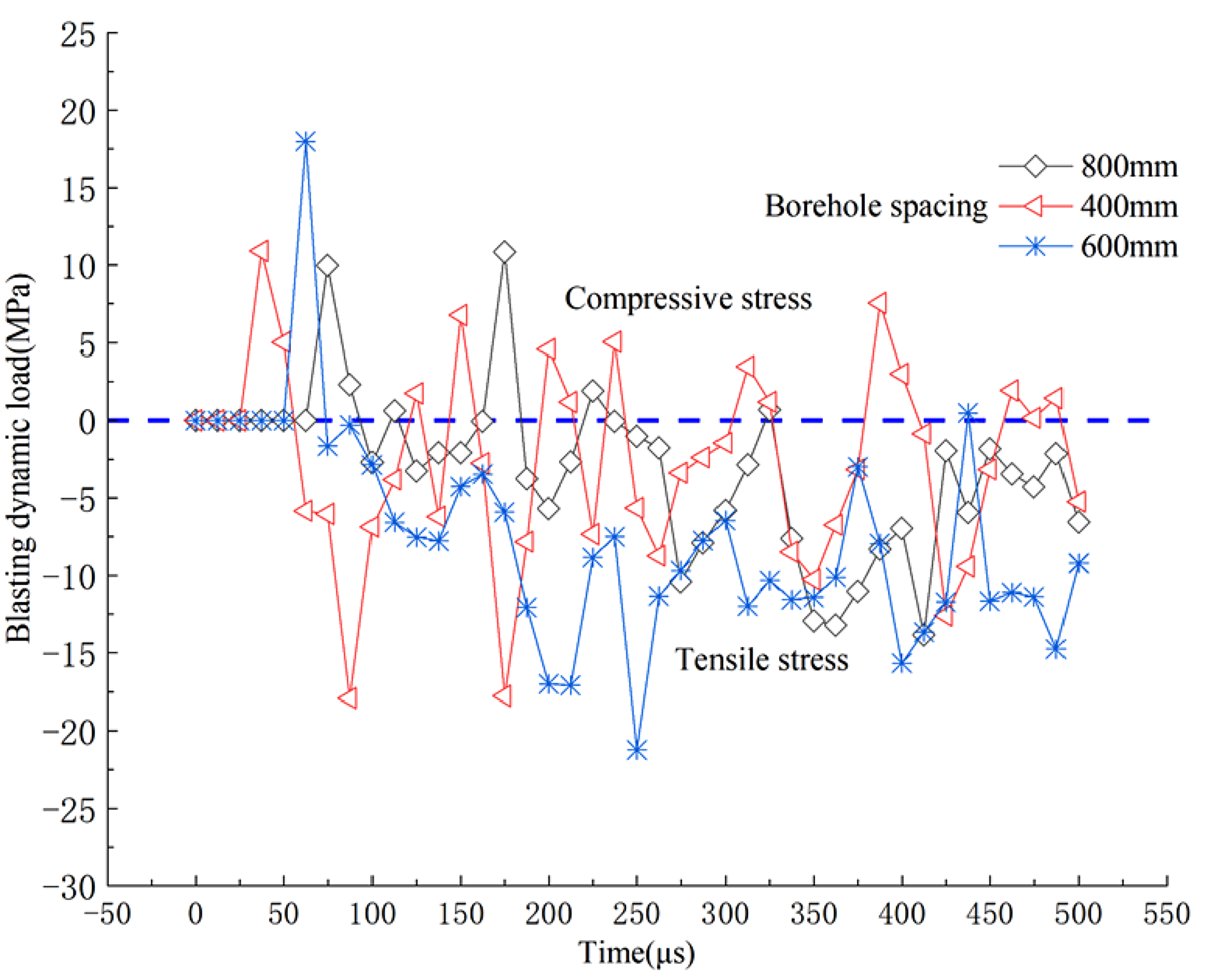
Stress change between holes in different time.
According to the LS-DYNA numerical calculation software, the compressive stress is positive and the tensile stress is negative. It can be seen that when two holes are blasting at the same time, the midpoints of the connecting lines between different holes show alternating action of tensile stress and compressive stress. Because the rock mass has the characteristics of resisting compression and being afraid of tension, when the tensile stress is larger than the tensile strength of the rock mass, a part-through crack will occur. With the increase of time, the frequency of alternating action of tension and compression and the peak value of stress at the midpoints of the connecting lines between holes decrease. When the hole spacing is 400 mm, the alternate action frequency of tension and compression at the midpoint of the hole connection line is the most, with the longest action time. When the hole spacing is 600 mm, the action time of tensile stress is longer than that of compressive stress, and the peak value of maximum compressive stress and tensile stress is larger than that of 400 mm. When the hole spacing is 800 mm, the superposition value of the stress value of the alternating tension-compression transformation at the midpoint of the hole connection line is small, and the peak value of the alternating tension-compression action is small, which shows that the part-through crack cannot be produced at the midpoint of the hole connection line. The alternating tension-compression effect causes cracks in rock mass along the line of hole connection. When the alternating tension-compression strength is lower than the cracking strength of rock mass, no cracks can be produced.
In summary, the law of crack propagation in shaped-charge blasting and non-shaped-charge blasting, different linear charge density and different hole spacing are studied by numerical simulation. The results show that:
when the linear charge density is 1.1 g·cm−1 with the use of the shaped-charge blasting, the cracks extend linearly along the shaped-charge direction after the explosion, and when the hole spacing is 400 mm and 600 mm, the part-through cracks can be produced, to achieve the effect of cracking; When the hole spacing is 800 mm, no part-through crack can be formed. By using non-shaped-charge blasting, the cracks around the blasting holes extend in double “X” shape along the hole connection line and the vertical connection line. When the hole spacing is 600 mm, no part-through cracks can be produced, but the crack propagation along the vertical hole connection line is obvious. When the linear charge density is increased to 1.5 g·cm−1 and the hole spacing is 600 mm, in case of using shaped-charge blasting, the part-through cracks are formed between the lines of the two holes, and the crack propagation in the direction of retained rock mass is obvious. When two holes are blasted at the same time, tensile stress and compressive stress alternate at the midpoint of the connecting line with different hole spacing. When the tensile stress is larger than the tensile strength of the rock mass, a part-through crack will occur. With the increase of time, the frequency of alternate tension-compression action and the peak value of stress decrease at the midpoint of the connecting line of the hole.
Engineering verification
Design of pre-splitting blasting parameters
From the above study, it can be seen that the crack propagation of rock mass in shaped-charge blasting is longer than that in non-shaped-charge blasting, and shaped-charge blasting is one of the effective ways to realize roof-cutting and crack-forming. In order to ensure that the cracking of the roof of gob-side entry retaining by roof cutting and the integrity of the roadway roof, the maximum hole spacing and the minimum charge length that can form part-through cracks are generally selected in engineering applications. Therefore, according to the physical and mechanical parameters of the roof rock strata of 7135 working face in Qidong Coal Mine, a level three permissible water gel explosive for coal mine is adopted. The hole diameter is 50 mm, the explosive parameters are: diameter Φ = 35 mm, l = 400 mm, weight m = 0.44 kg, the design hole spacing is 0.6 m, the charge length is 4 m, and the hole sealing depth is 2 m. Pre-splitting blasting is carried out at 50–60 m advanced working face. The blasting technology is shaped-charge blasting, using reverse charging, simultaneous blasting of the hole, and reverse detonation in the hole, as shown in Figures 10 and 11.
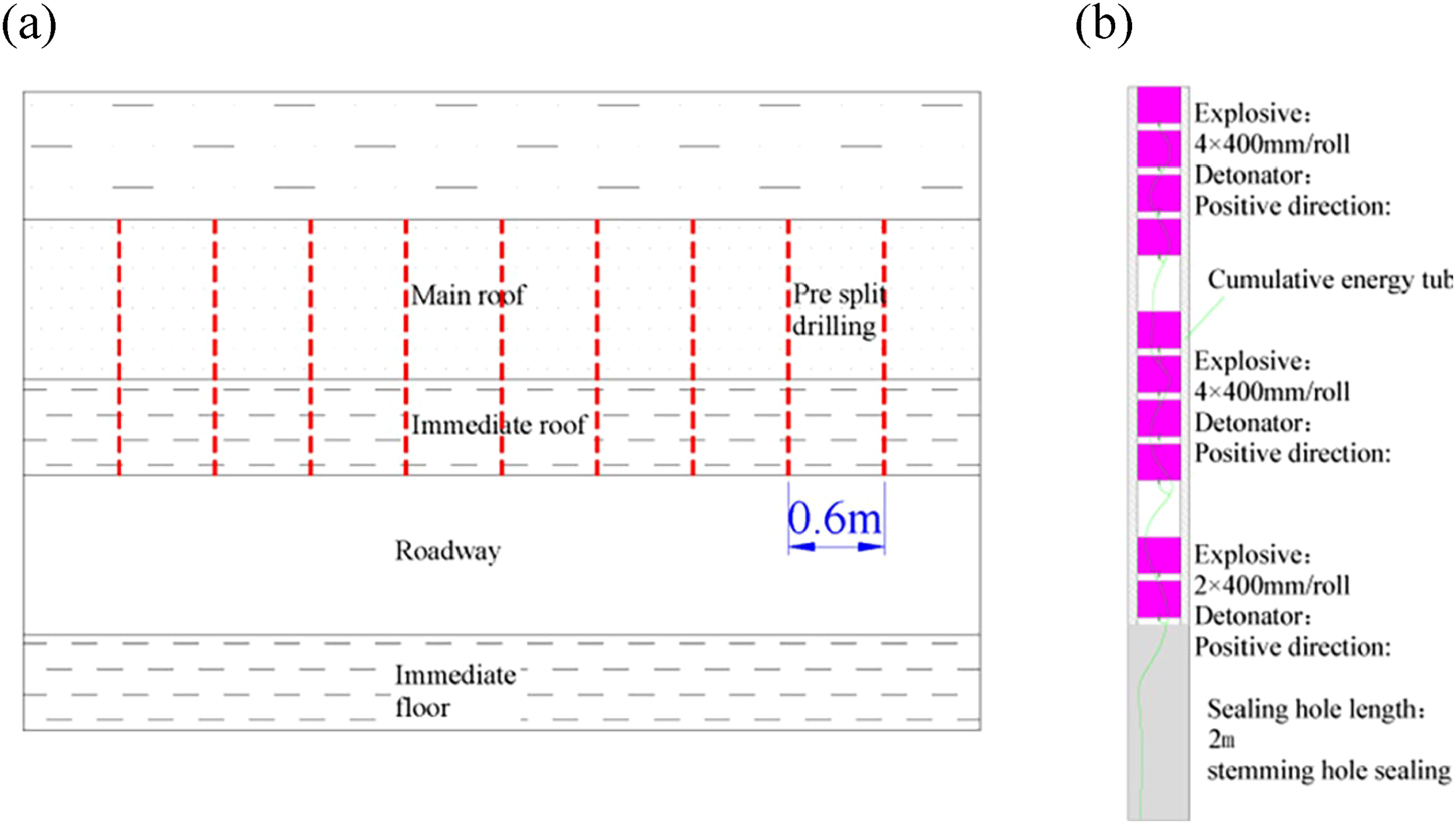
Hole spacing diagram: (a) layout of hole spacing and (b) charge structure.
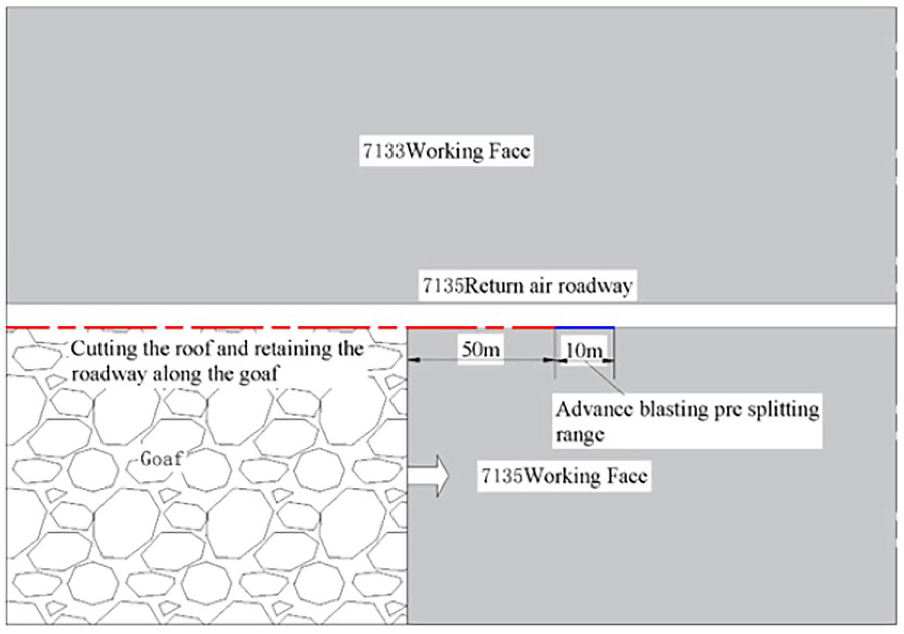
Schematic diagram of pre-splitting blasting range.
Investigation of pre-splitting blasting effect
After advanced pre-splitting the roadway roof, drilling holes in the middle of the two holes to observe the development of rock strata fractures in the holes. Because the observation borehole is constructed by the roof bolter, the diameter of the hole is Φ28 mm, and the hole is limited by the diameter of the peeping probe and the length of the guide rod during the peeping process of the borehole, the peeping depths of the 52 m and 56 m, construction observation boreholes are 7.3 m and 6 m, respectively. After the pre-splitting blasting of the roof, the surface cracks of the roadway roof are observed. As shown in Figure 12, the cutting in the charging section of the blasting hole are obvious, and the distribution of the cuttings are symmetrical linear, which is in line with the characteristics of shaped-charge blasting. Comparing the crack section with the blasting depth, it can be obtained that the cracking rate reaches 86% to 90%, and the blasting cracking and the stability effect of the roadway roof is good.
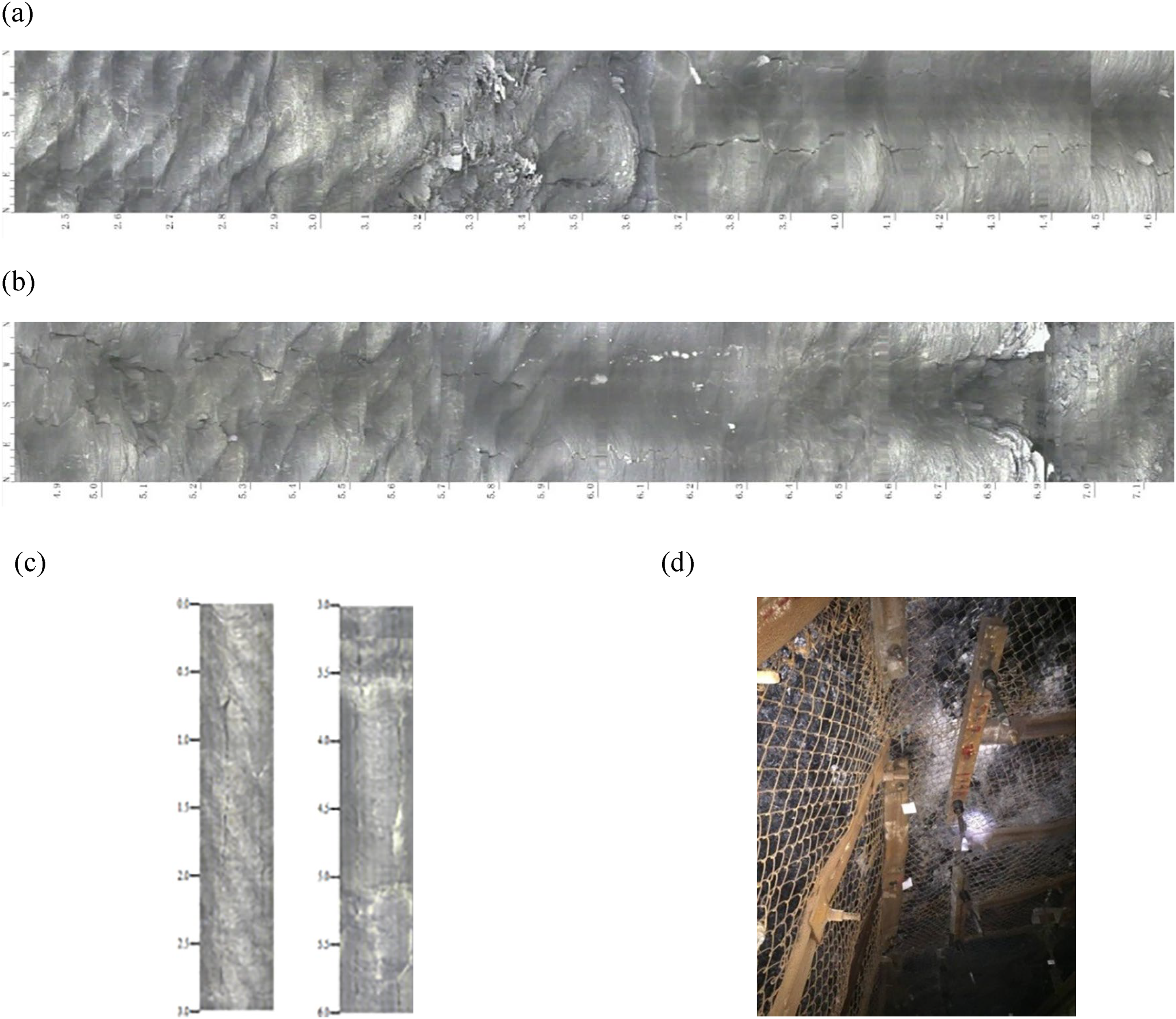
Observation of cutting effect :(a) hole depth of 2.5–4.8 m at 52 m peep effect; (b) hole depth of 4.8–7.3 m at 56 m peep effect; (c) peep effect of 6 m hole at the depth of 56 m; (d) observation of roof integrity.
Stress change of anchor cables
The anchor cable stress monitoring points are arranged 100 m in front of the working face of the roof-cutting roadway, and the stress change curve of the reinforcing anchor cables measured is shown in Figure 13.
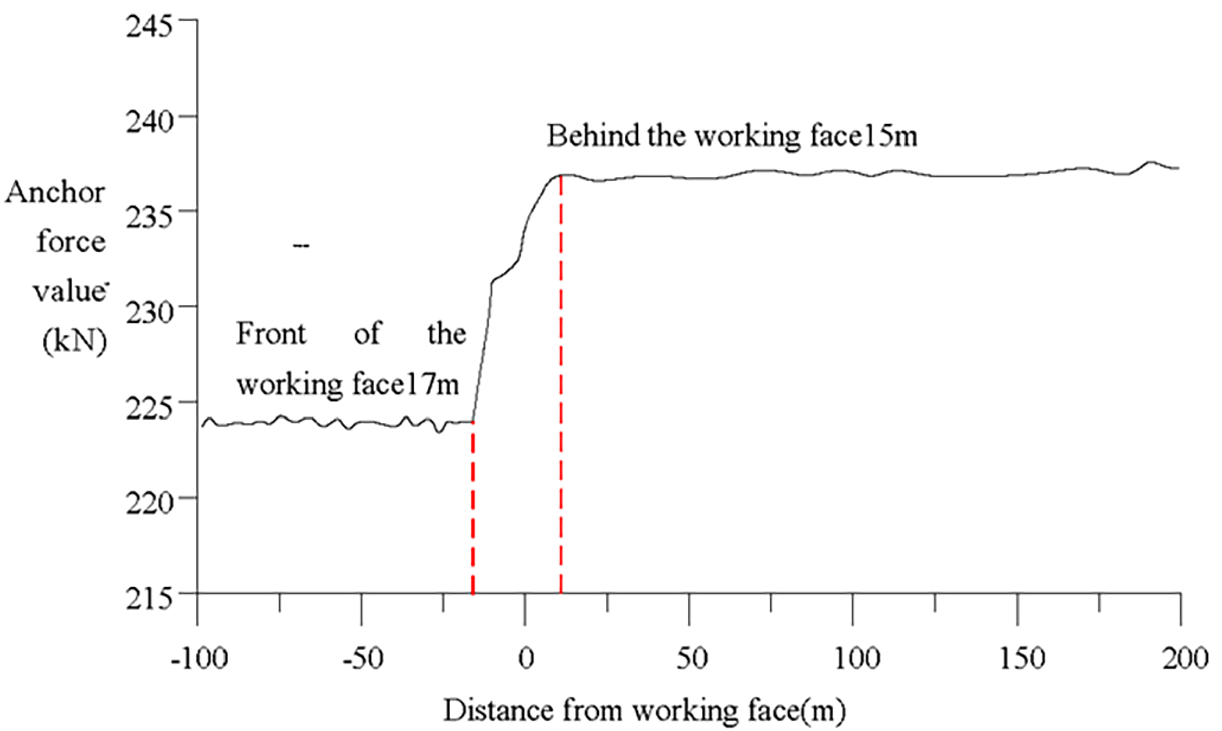
Anchor cable stress variation.
It can be seen from the figure that the influence of mining stress is weak outside the 17 m range of the advanced working face, and the stress value of the anchor cable is stable at 224 kN after the roof cutting by advanced pre-splitting blasting. Under the influence of mining stress, the stress value of the anchor cable increases continuously within 17 m of the advanced working face, and reaches the maximum value at 15 m of the lagging working face, and the monitoring maximum stress value is 237 kN. Subsequently, the working face continues to advance, and the stress value of anchor cables decreases slightly and tends to be stable. During the monitoring process from 100 m advanced working face to 200 m lagging working face, the maximum stress of the anchor cable is 237 kN, which is 13 kN larger than the initial stress of 224 kN, and the increase is about 5.8%, which is 41% of the tensile strength of the anchor cable. The effective load-bearing surplus space of the anchor cable is about 59%. The stress state of the anchor cable is good, and the roof can be effectively controlled.
Conclusions
Under the same blasting condition, the energy of shaped-charge blasting in shaped-charge direction is much larger than that of non-shaped-charge blasting. When the tensile stress generated by blasting stress wave is larger than the tensile strength of rock mass, cracks will occur in rock mass, and the cracks along the shaped-charge direction will be longer than that of non-shaped-charge blasting. It is obtained that the key parameters of pre-splitting cracking are hole spacing and charge length.
The crack propagation law of two holes blasting at the same time is studied with different blasting methods, different linear charge density, and different hole spacing. In the case of shaped-charge blasting, the crack of different hole spacing extends linearly along the direction of shaped charge, while in the case of non-shaped-charge blasting, the crack around the hole extends in double “X” shape along the direction of hole connecting line and vertical connecting line, and the effect of shaped-charge blasting with the same hole spacing is better than that of non-shaped-charge blasting, showing that it can form part-through cracks; Increasing the linear charge density can increase the cracking distance and destroy the integrity of the retained rock mass at the same time.
The key parameters of advanced pre-splitting blasting in engineering practice are put forward. Generally, the maximum hole spacing and the minimum charge length that can produce part-through cracks are selected. When shaped-charge blasting is adopted in the return airway of 7135 working face of Qidong Coal Mine, the hole spacing is 600 mm, and the charging length is 4 m, the roof crack propagation and the stress change of anchor cable after blasting are measured. The results show that the cuttings in the charging section of the holes are obvious, and the cuttings are distributed in a symmetrical linear pattern, and the cracking rate reaches 86%∼90%; The anchor cable is in good condition and can effectively control the roof.
Footnotes
Acknowledgments
The authors thank the Qidong Coal Mine for the measured data. Mr Peng Yang of Anhui University of technology is thanked for his assistance with data analysis.
Declaration of conflicting interests
The authors declared no potential conflicts of interest with respect to the research, authorship, and/or publication of this article.
Funding
The authors disclosed receipt of the following financial support for the research, authorship, and/or publication of this article: This work was funded by National Natural Science Foundation of China (grant numbers 52374075 and 51774010).