
Abstract
Severe deformation of surrounding rock and excess-gas are the main problems faced in mining of high-gas coal seam. This paper analyzes the deformation characteristics and mechanical model of surrounding rock in high-gas coal seam, and proposes the control technology of surrounding rock deformation and gas prevention and control. Based on this, the entry automatically formed by roof cutting (EAFRC) surrounding rock control technology and constant resistance large deformation anchor cable (CRLDA) support control technology in Shaqu coal mine are put forward. At the same time, the surrounding rock stress and gas migration law of the working face under traditional mining method and EAFRC mining were compared and analyzed. Through the field engineering test, the monitoring and analysis of surrounding rock deformation and gas concentration, the average surrounding rock deformation of roof cutting roadway is 310 mm, and the gas concentration of retained roadway by roof cutting is 0.31%. Through the research in this paper, the surrounding rock stability and gas control of the working face have been realized, and the non-pillar mining of EAFRC has ensured the safe mining of high gas working faces, which provides a reference for the mining of similar mines in non-pillar mining. At the same time, the technical system of EAFRC in non-pillar mining was established, which promoted the development and application of non-pillar mining.
Keywords
Introduction
With the increasing demand for coal resources in economic development, the safety problem of coal mining is becoming increasingly prominent. At present, the method of retaining coal pillar longwall mining is mainly used in underground coal mining (Manchao et al., 2017; Peng et al., 2019). The size of the coal pillar is the main key to mining by this method. Setting the size of coal pillar is the main key to this method of mining. Cheng et al. (2010) has carried out research and analysis on the reasonable size of coal pillar. The width of coal pillar is too wide, which aggravates the waste of coal resources. The small width of coal pillar results in stress concentration and serious deformation and destruction of roadway surrounding rock (Yan et al., 2012), as shown in Figure 1(a). At the same time, for the gas mine, the gas in the corner of the working face exceeds the limit, which seriously restricts the safe and efficient production of the mine (Heping et al., 2014; Liu et al., 2023; Yingming et al., 2013).
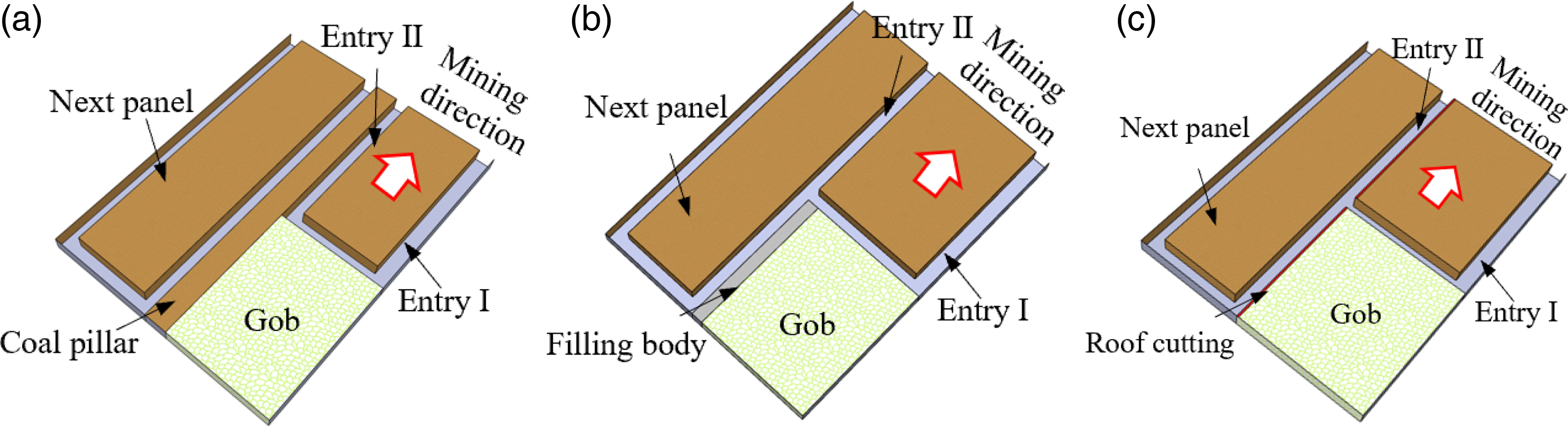
The technique of coal mining: (a) setting coal pillar traditional coal mining, (b) gob-side entry retaining by filling mining and (c) entry automatically formed by roof cutting.
In order to solve the problem of serious deformation of surrounding rock of roadway, researchers have proposed a non-pillar mining technology of gob-side entry retaining by filling body (Zhang et al. 2012). This technology retains the roadway by artificially filling the wall on the side of the gangue in the goaf. According to the types of filling materials, it mainly includes cement mortar flexible mold filling, paste filling (Zheng et al., 2006), fly ash filling (Xu et al., 2011) and other filling methods (Tan et al., 2015; Zhou et al., 2012). Although it can reduce the number of roadway excavation, it is the main direction of non-pillar mining. However, this technique has the problem of stress concentration caused by the filling body (Jiaguang et al., 2011; Yunhai et al., 2012), as shown in Figure 1(b). Therefore, although this technology can cancel the retention of coal pillar, it is difficult to effectively solve the problem of large surrounding rock pressure and deformation due to the stress concentration caused by the filling body, and the stability of the filling body has been greatly affected. The traditional mining and gob-side entry retaining by filling body are difficult to realize the joint control of surrounding rock and gas. Therefore, the method of joint control of surrounding rock and gas needs to be further studied.
Thus, He et al. (2017) proposed the directional pre-splitting roof cutting and pressure relief technology, as shown in Figure 1(c). Through the supporting technologies such as directional pre-splitting roof cutting technology and constant resistance large deformation anchor cable support technology (Zhigang et al., 2020; He et al., 2018) and other supporting technologies (Wang et al., 2020; Gao et al., 2019). This technology realizes the pre-splitting cutting of the roof and cuts off the stress transfer of the roof in the goaf. By making use of the roof pressure and the broken expansion characteristics of gangue in the goaf, the automatic formation of roadway without coal pillar is realized. Based on this background, this paper analyzes the mechanism of entry automatically formed by roof cutting (EAFRC), and studies the surrounding rock and gas control of gas coal seam roadway in Shaqu coal mine. The research results show that the surrounding rock pressure and gas of the roadway can be controlled by directional pre-splitting. This study provides a reference for non-pillar mining of EAFRC in high gas coal seam.
Engineering geological conditions
The 4303 working face is the mine's first EAFRC test working face. The buried depth of the working face is 430 to 469 m, the thickness of the coal seam is 2.1 to 2.9 m, and the average thickness is 2.7 m. The dip angle of the coal seam layer is 4° to 8°, the average dip angle is 6°. The inclined length of the working face is 210 m, and the strike length is 1037 m. The absolute gas emission of the working face is 34.79 m³/min, the residual gas content of the coal seam before mining is 4.60 m³/t, and the gas pressure is 0.35 MPa. U-shaped ventilation is often used in traditional mining working faces, which easily leads to excessive gas at the corners of the working face. After non-pillar mining of EAFRC is adopted, the fresh air will enter from the 4303 haulage entry and the 4303 ventilation entry, and the air will return from the retained roadway by roof cutting, and the working face will change from U-shaped ventilation to Y-shaped ventilation. The layout of the 4303 working face in Shaqu coal mine is shown in Figure 2.
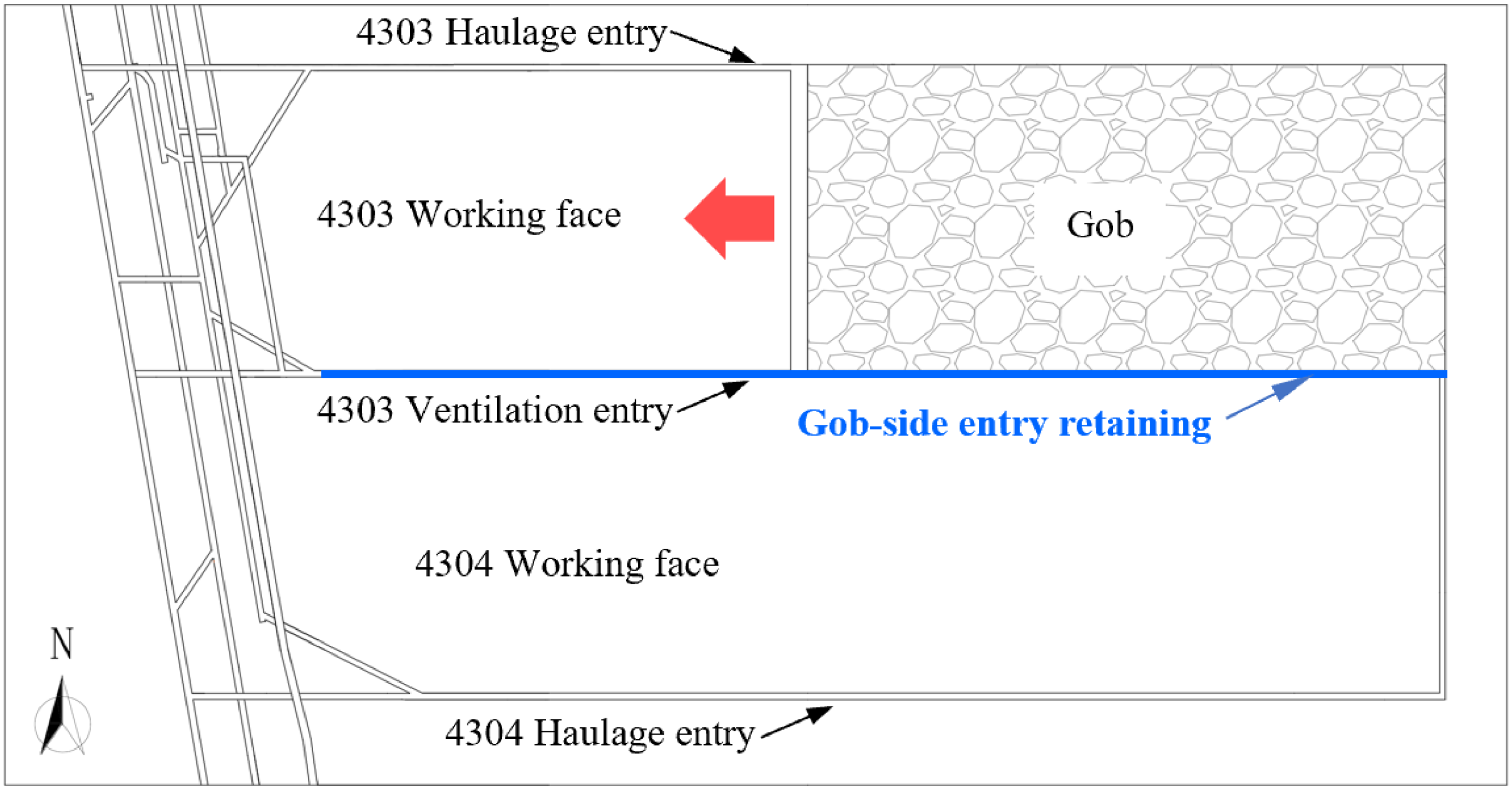
The layout of 4303 working face.
The roof of 4303 working face is mainly made of sandy mudstone and siltstone, and the floor of the No. 4 coal seam is made of sandy mudstone and fine sandstone, with thicknesses of 0.5 and 5.5 m, respectively. It can be seen from the columnar shape of the drill holes in the 4303 working face that the No. 3 coal and the No. 4 coal gangue are sandy mudstone and sandstone with a thickness of 0.8 to 1.8 m and an average thickness of 1.05 m. The columnar lithology of the working face is shown in Figure 3.
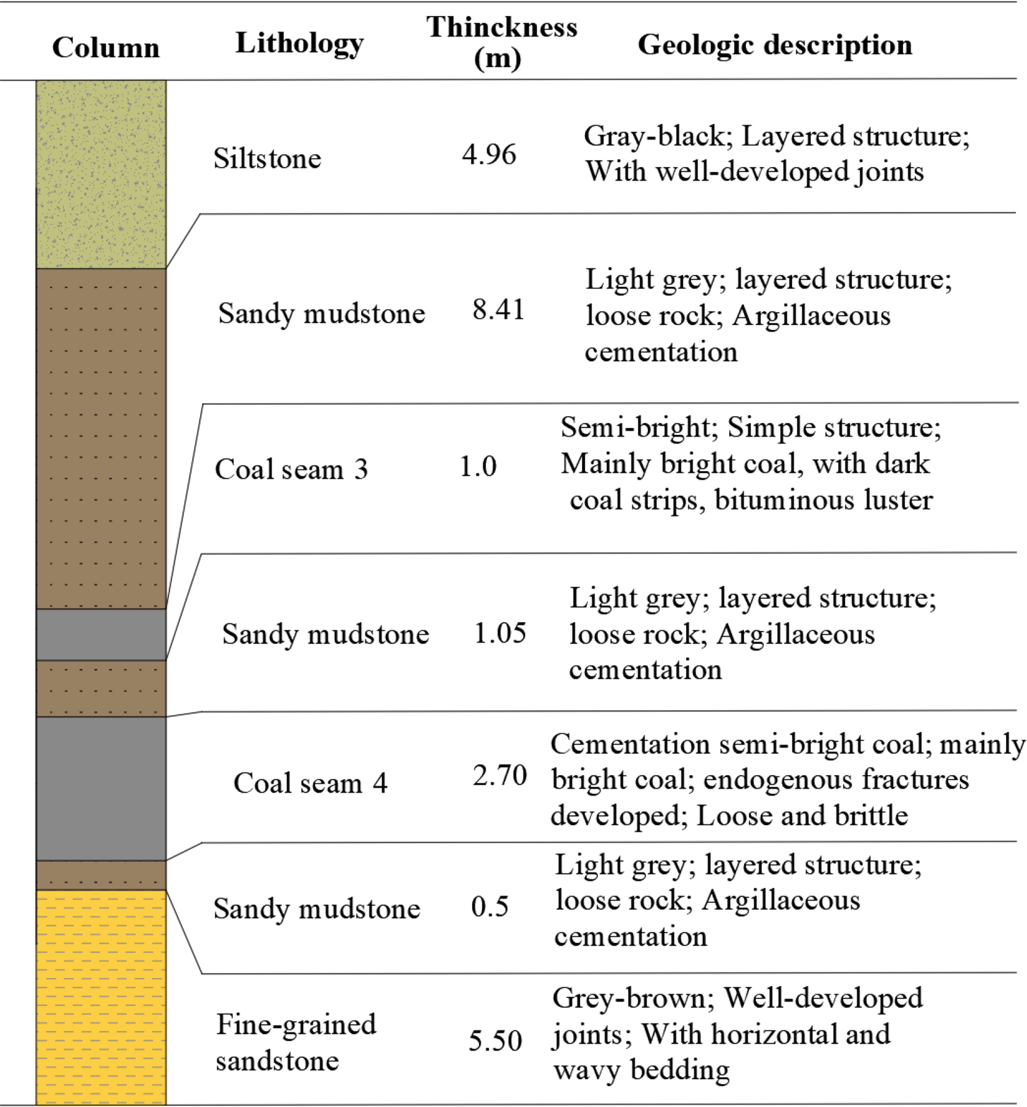
Stratum synthesis histogram of 4303 working face.
Principle of entry automatically formed by roof cutting
Analysis on rock structural of entry automatically formed by roof cutting
The traditional method of longwall mining further aggravates the situation of decreasing coal resources because of the need to leave sections of coal pillars, which will form higher stress concentrations in the process of adjacent working face retrieval and easily cause mine disasters (Huang et al., 2021; Xie et al., 2011), as shown in Figure 4(a). Meanwhile, the working face retrieval needs to dig two roadways, which will easily cause the situation of mining succession tension. Therefore, the underground coal mining technology needs to be further optimized.
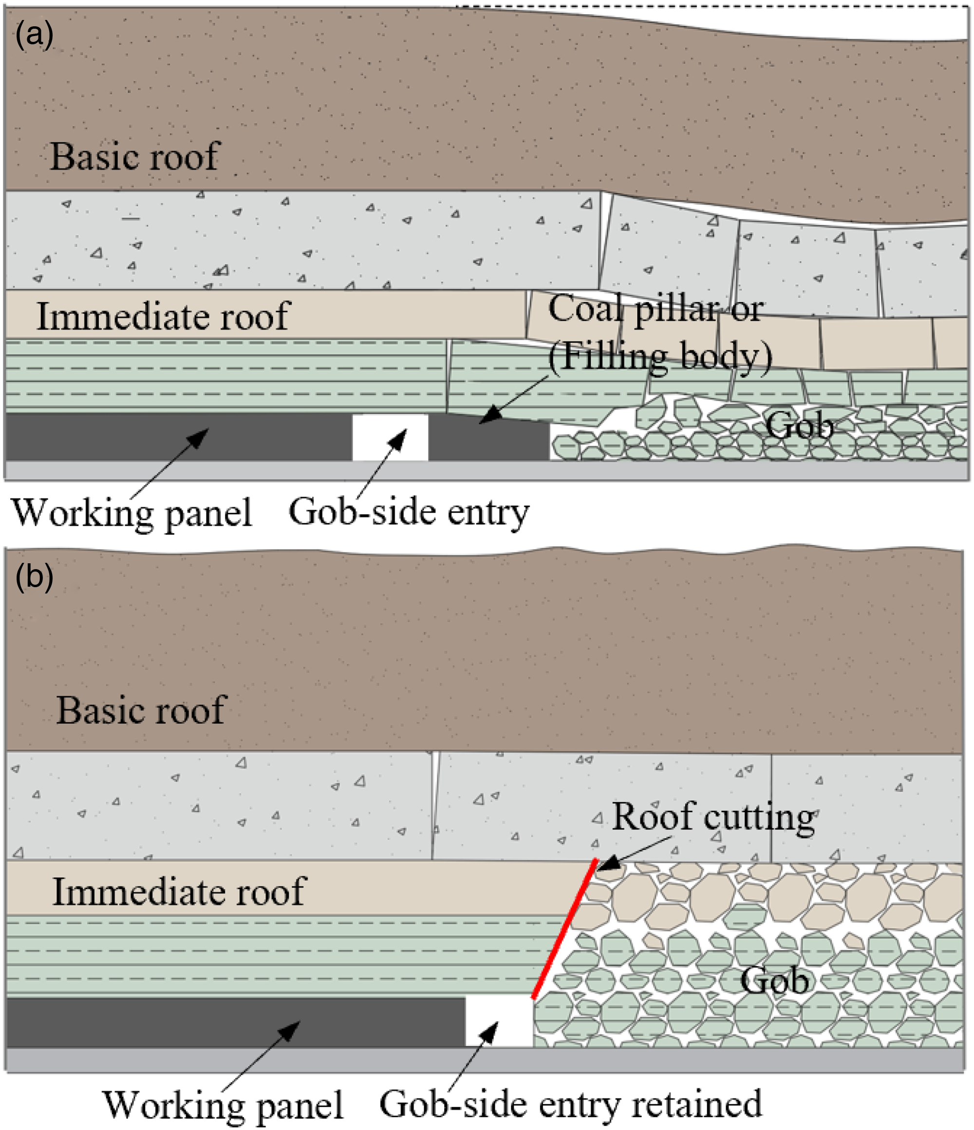
Roof structural features of mining: (a) structural characteristics of traditional mining and (b) structural characteristics of entry automatically formed by roof cutting.
Non-pillar mining eliminates the section coal pillar in the mining area of the working face, and continues to be used for the next working face by maintaining the roadway left in the working face (Chen et al., 2012). Among them, the traditional way to retain the roadway is through the use of artificial filling wall on the gangue side of the mining area to protect the roadway. And according to the category of filling materials mainly including cement mortar soft mold filling, paste filling, fly ash filling and other filling methods, as shown in Figure 4(a).
And EAFRC technology, through the directional pre-splitting cut off the roof stress transfer, cut off the stress transfer between the roof of the entry and the roof of the mining area (Gao et al., 2021; Manchao et al., 2018). And it improves the stress environment of the retained entry surrounding rock, while using the collapse of the roof plate of the mining area of the gangue crushed expansion characteristics to fill the mining area, as shown in Figure 4(b). The roof cutting height of the working face can be calculated by formula (1).

The average thickness of No. 4 coal seam is 2.7 m. Combined with the actual situation of the working face, according to the lithology of the roof of the 4303 working face, the breaking expansion coefficient is taken as 1.35. The roof cutting depth of EAFRC is 8 m. In order to reduce the impact on the roof of the roadway, the roof cutting angle is taken as 15°.
Key technologies of entry automatically formed by roof cutting
Directional pre-splitting of the roof is the key to roof cutting and pressure relief in non-pillar coal mining and surrounding rock deformation control, through directional pre-splitting of the slit to form a short arm beam of roof cutting, reducing the impact of rock collapse on the roof of the retained entry. It increases the space for rock fragmentation and expansion of the roof of the mining area. At the same time, using the characteristics of rock fragmentation and expansion, filling the mining area to form the gangue gang of the roof cutting into the roadway. Directional pre-splitting technology transforms the long-armed beam of the roof into a short-armed beam structure to transfer the stress of the quarry area to the deep part of the surrounding rock. The principle of directional pre-splitting is shown in Figure 5.
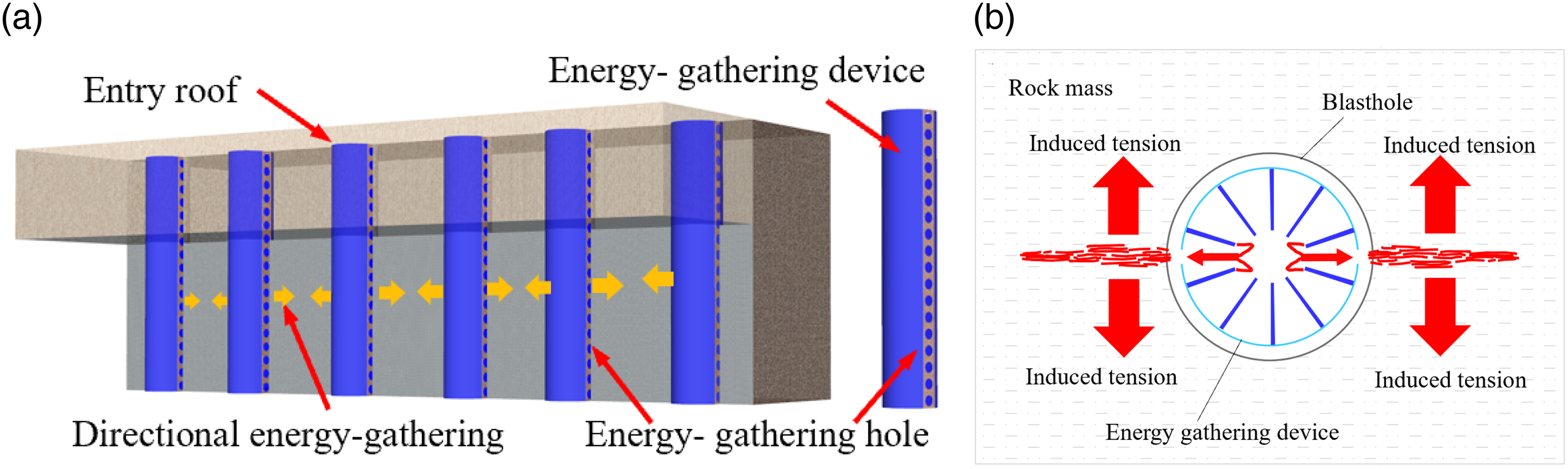
Principle of directional roof cutting fusion blasting: (a) directional roof pre-slitting mechanism and (b) the principle of fusion blasting.
Due to the influence of dynamic pressure of working face back mining, the deformation control of the retained entry surrounding rock has the characteristics of large surrounding rock deformation and high load. Therefore, the support material is required to have the characteristics of high constant resistance, large deformation and impact resistance. The constant resistance large deformation anchor cable (CRLDA) proposed by academician He’s team (He et al., 2018), which has the characteristics of high constant resistance and large deformation and can adapt to the characteristics of large deformation of the surrounding rock. The structure of constant resistance large deformation anchor cable is shown in Figure 6. The deformation of constant resistance anchor cable includes stage I, stage II and stage III, which determines that the constant resistance anchor cable can adapt to the large deformation of surrounding rock. Through the joint action of constant resistance large deformation anchor cable support, combined with temporary reinforcement support in the entry and gangue gang support, the overlying rock reversal surrounding rock deformation has been effectively controlled, thus improving the stability of the surrounding rock in the retained entry.
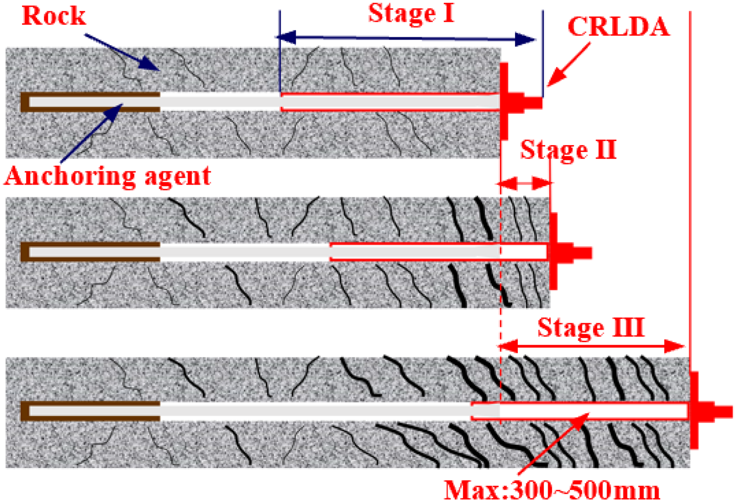
The deformation characteristics of CRLDA.
Study on stress distribution and gas migration laws of entry automatically formed by roof cutting
Numerical model
In order to compare and analyze the stresses and gas transportation law between the traditional mining method and the EAFRC method, a numerical analysis model as shown in Figure 7 was established according to the actual geological conditions of the 4303 working face of Shaqu coal mine. The traditional mining model is shown in Figure 7(a), and the numerical model of EAFRC is shown in Figure 7(b), with the model size of 400 m × 300 m × 60 m.
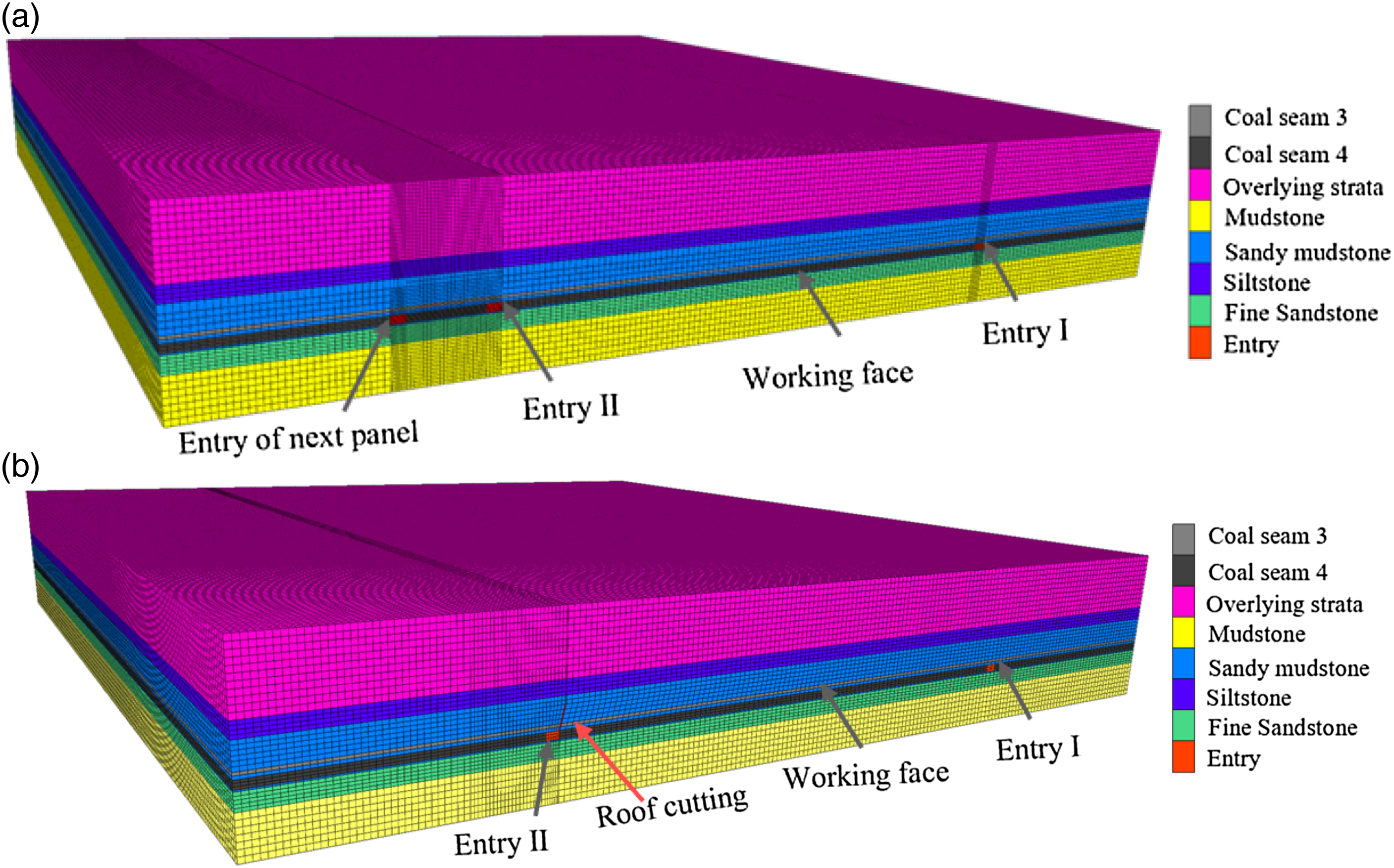
Numerical calculation and analysis model under different mining methods: (a) numerical analysis model for traditional mining and (b) numerical analysis model for EAFRC.
The lower boundary of the numerical calculation model is fixed vertically, the front and rear, left and right boundaries are fixed horizontally, and a vertical downward stress is applied to the upper surface. The burial depth of the coal seam is taken as 467 m, and the Mohr–Coulomb model is chosen for the rock seam intrinsic model, and the physical and mechanical parameters of the simulated rock seam are shown in Table 1.
Rock mechanics parameters of 4303 working face.

Analysis of numerical simulation results
After the new technology of roof cutting and pressure relief was adopted in the working face, the stress distribution characteristics of the working face were changed. In order to analyze the stress distribution characteristics of the working face under different mining techniques, six stress measurement lines were arranged in the working face. The measuring lines 1, 2 and 3 are arranged along the working face in the direction of back mining, and the measuring lines 4, 5 and 6 are arranged along the vertical direction of the working face, as shown in Figure 8. The measuring line 1 is located 6 m from the roof cutting side of the working face, the measuring line 2 is located in the middle of the working face, and the measuring line 3 is located 6 m from the non-roof cutting side of the working face. The measurement lines 4, 5 and 6 are located at 6 m, 10 m and 20 m, respectively, on the overrunning working face. In the position of the gob-side retained entry by roof cutting into the solid coal gang, the measurement line 7, 8 and 9, in turn, the distance from the working face is 5 m, 30 m and 100 m. The stress measurement line arrangement is shown in Figure 8.
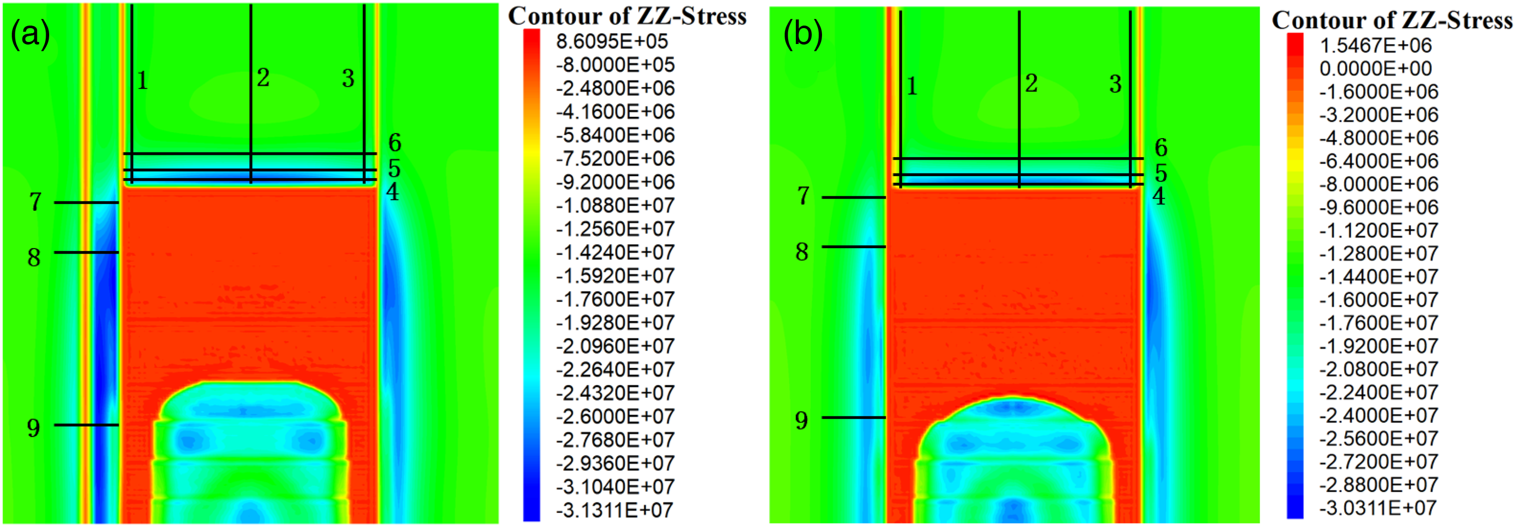
Stress distribution characteristics of working face and measurement line arrangement: (a) traditional mining and (b) entry automatically formed by roof cutting.
Distribution law of overstress in working face
Distribution law of overstress in working face orientation: With the increase of the distance from the working face, the overpressure shows the characteristics of first increasing and then decreasing. On the roof cutting side of the working face, the peak stress of the traditional mining line 1 is 24.6 MPa. And the peak stress of the line 1 non-pillar mining method is 18.01 MPa, which is 26.7% lower than that of the traditional mining method, as shown in Figure 9(a). In the middle position of the working face, the peak stress of line 2 is 28.3 MPa in traditional mining, and the peak stress of line 2 is 26.2 MPa when gob-side entry retaining by roof cutting, which is 7.4% lower than that in traditional mining, as shown in Figure 9(b). On the non-roof cutting side, the trend of stress variation of the measured line 3 is similar for both mining methods, as shown in Figure 9(c). The results show that the roof cutting and pressure relief effectively reduces the overstress of the working face on the roof cutting side, which is beneficial to the stability of the roadway.
Distribution law of overstress in working face tendency: In the direction of working face inclination, the change of overstress is shown in Figure 10. From the change law of measured lines 4, 5 and 6, it can be seen that the peak of working face tendency stress is about 8 m from the coal gang during traditional mining, and the peak of working face tendency stress is shifted to the middle of working face when using roof cutting method. And the roadway on the side of gob-side entry retaining by roof cutting is in the stress relief area, which is more conducive to the stability of the roadway. When gob-side entry retaining by roof cutting mining, the peak stress of working face is shifted to the deep part about 25 m. In the middle of the working face and the non-roof cutting side, the overpressure of the working face in the traditional mining method is greater than that in the gob-side entry retaining by roof cutting mining. The results show that the directional pre-splitting blasting of roadway by roof cutting has a significant pressure relief effect.
Lateral stress distribution pattern of solid coal in EAFRC
The change law of vertical stress on the solid coal side of the working face is shown in Figure 11. And the change law of the stress monitoring curve of the working face shows that the vertical stress on the solid coal gang during traditional mining is not conducive to the stability of the roadway due to the retention of coal pillars and the concentration of stress on the coal pillars on the solid coal body side. The peak vertical stress is reduced when using gob-side entry retaining by roof cutting mining compared with traditional mining. The peak of lateral vertical stress in the traditional mining method is 23.5 MPa, and the peak of stress in gob-side entry retaining by roof cutting is 18.7 MPa, which is 24.2% lower than the traditional mining method. The peak stress in the working face of the roof cutting entry is shifted to the deeper side than that of the traditional mining method. With the increase of the distance of lagging working face, the movement of the roadway surrounding rock gradually stabilizes. And the side stress of the solid coal gang in the mining area first increases and then tends to stabilize.
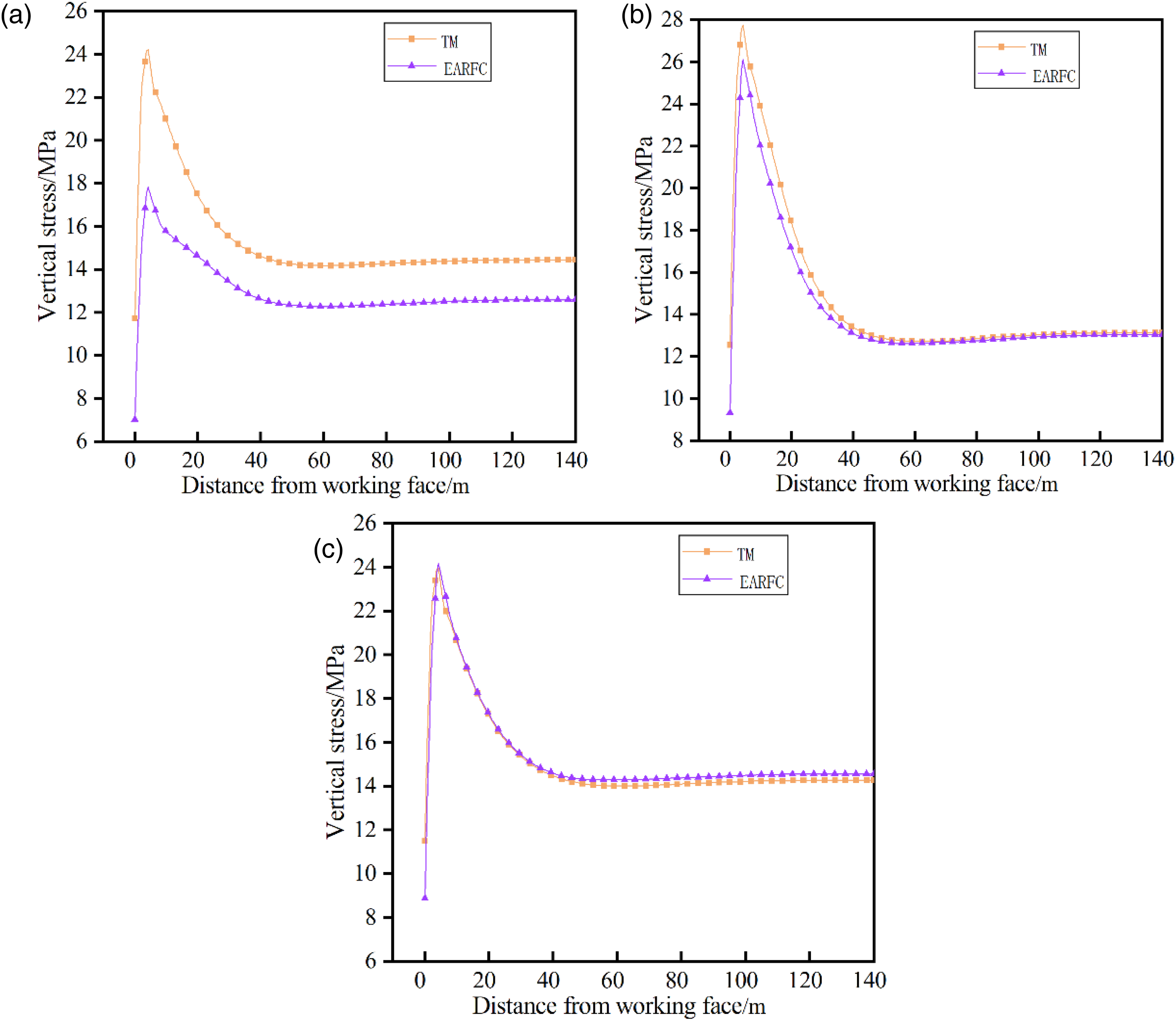
Overstress distribution pattern of working face orientation: (a) measurement line 1, (b) measurement line 2 and (c) measurement line 3.
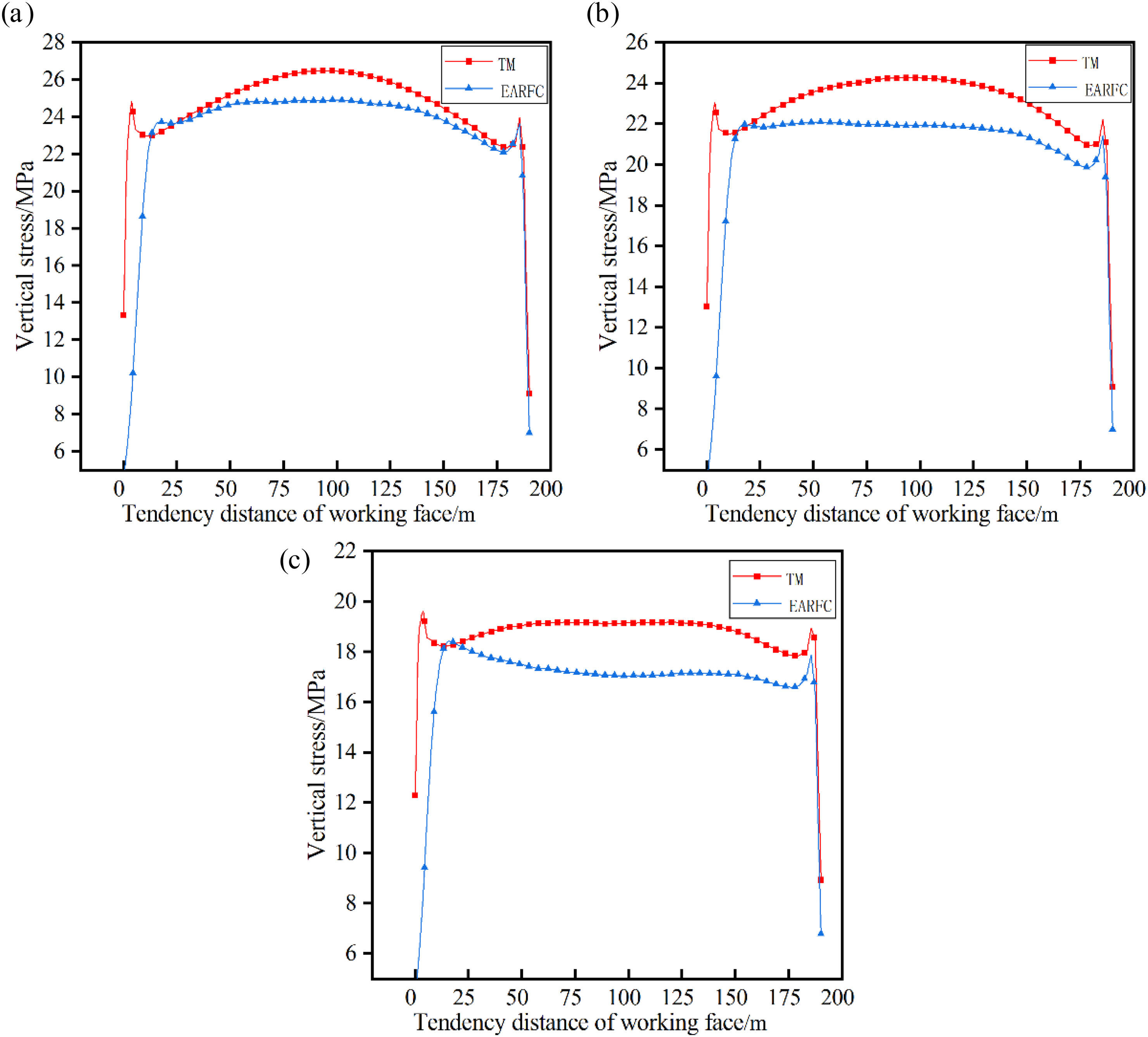
Overstress distribution pattern of working face tendency: (a) measurement line 4, (b) measurement line 5 and (c) measurement line 6.
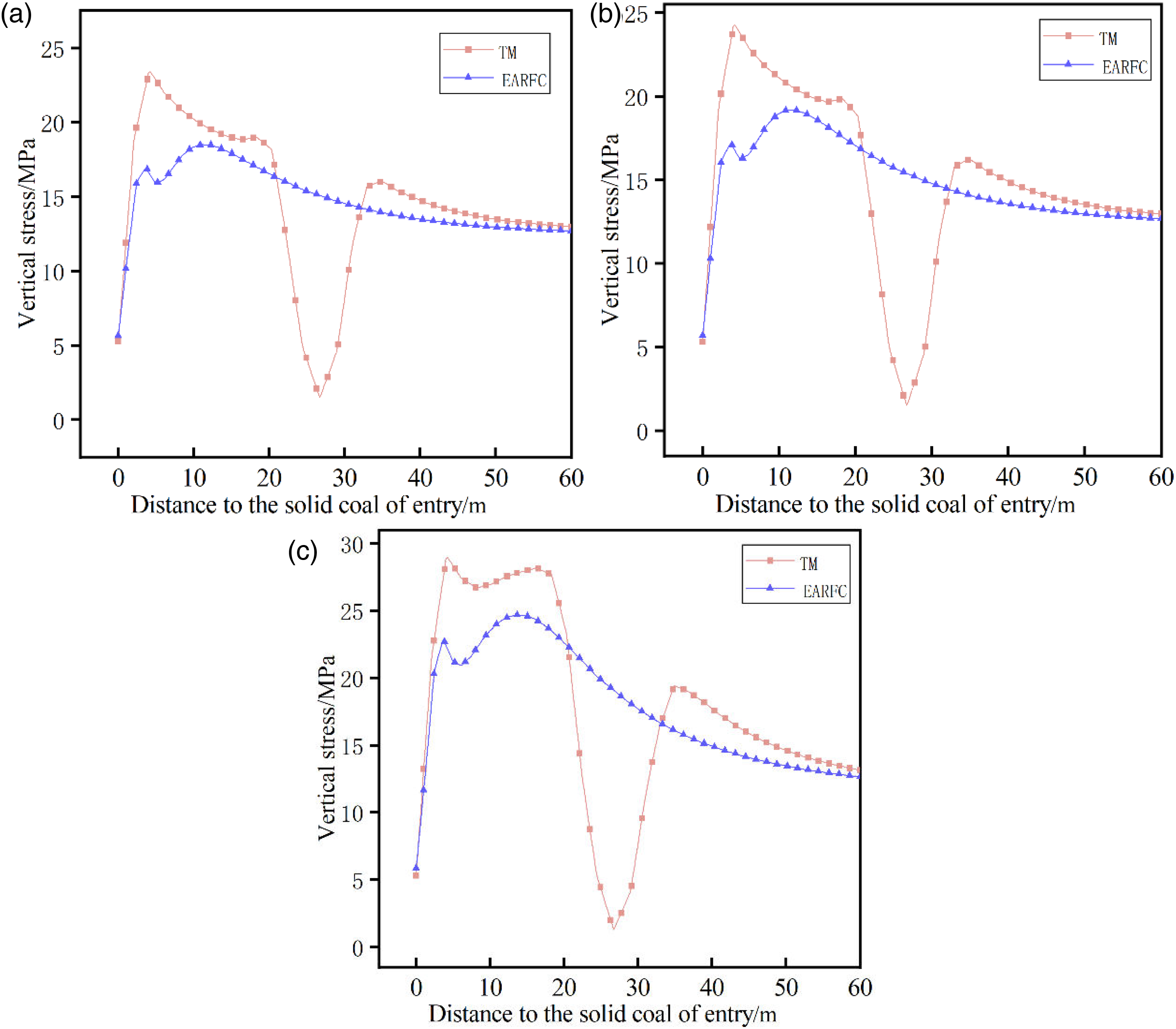
Lateral stress distribution law of solid coal: (a) stress distribution of measurement line 7, (b) stress distribution of measurement line 8 and (c) stress distribution of measurement line 9.
Gas distribution pattern of working face
Shaqu coal mine 4303 working face is a high gas coal seam. The traditional mining method adopts U-shaped ventilation, and after adopting the technology of EAFRC, the ventilation method is changed from U-shaped ventilation to Y-shaped ventilation, as shown in Figure 12. By comparing and analyzing the gas transportation law in the working face under different ventilation methods, it is of great significance to prevent and control the gas in the working face and ensure the safe and efficient production of the working face.
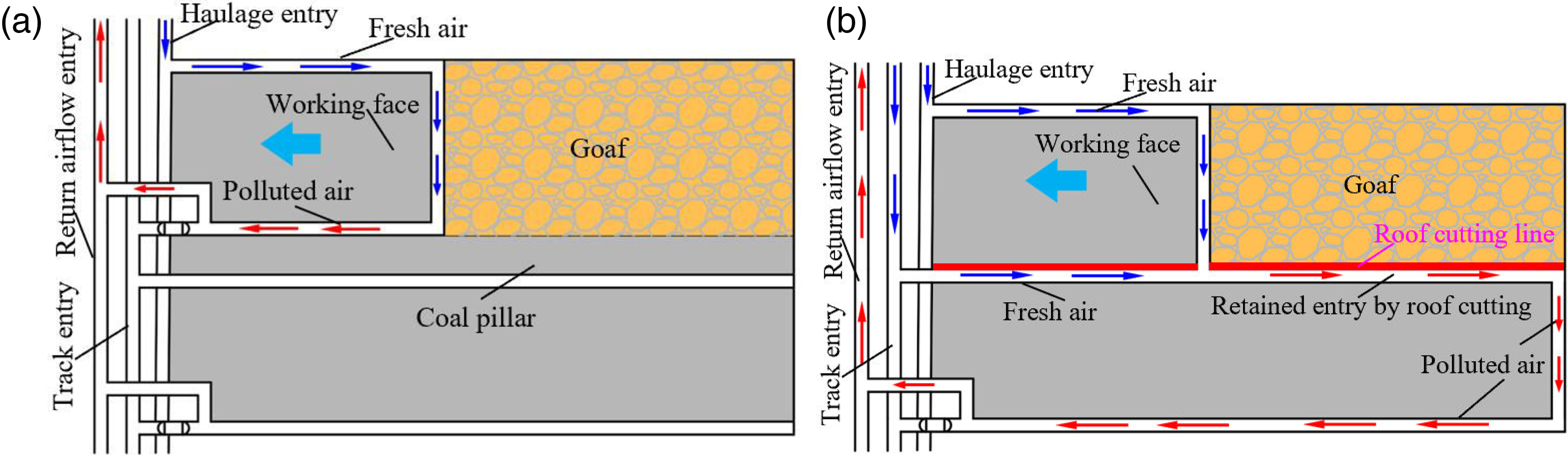
Ventilation of the working face: (a) U-shaped ventilation of traditional mining and (b) Y-shaped ventilation of EAFRC.
Through numerical analysis, the gas transport law in the mining area of different mining methods was obtained by numerical analysis as shown in Figure 13. The tendency gas distribution in the mining area is shown in Figure 14.
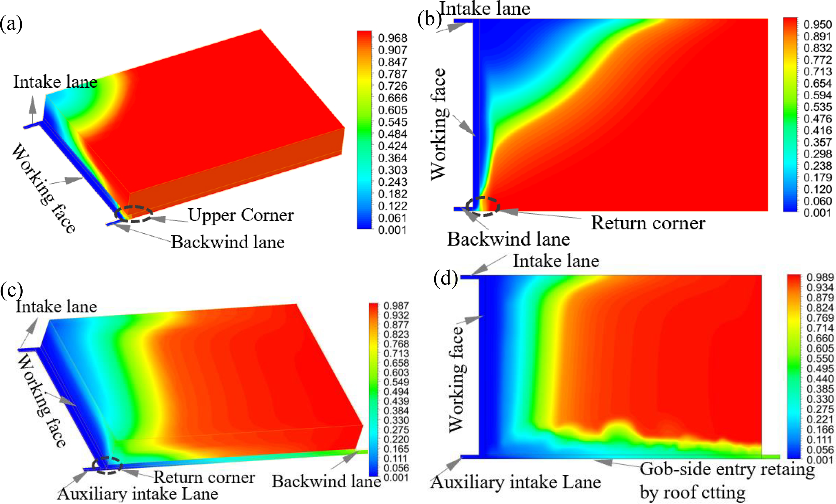
Gas transport pattern in the goaf under different mining methods: (a) gas spatial distribution of traditional mining, (b) gas plane distribution of traditional mining, (c) gas spatial distribution of EAFRC and (d) gas plane distribution of EAFRC.
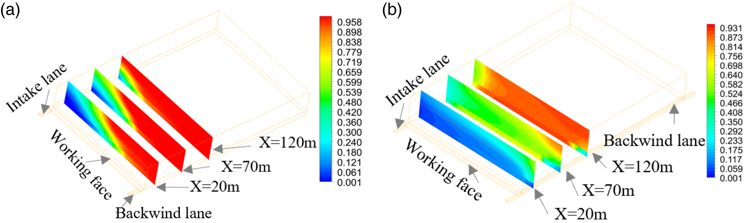
Gas distribution in goaf: (a) slice of gas distribution in goaf area of traditional mining and (b) slice of gas distribution in goaf area of EAFRC.
As shown in Figure 14, when U-shaped ventilation is adopted in traditional mining face, the air flow of the workings is fed by the intake lane and returned by the return lane. Gas accumulation is generated at the corner of the return lane of the working face, which is easy to cause gas over limit and restrict the safe production of the mine. And the gas concentration at the corner reaches 0.65%. After the adoption of the EAFRC method, the working face forms a ventilation mode of air intake from the intake lane and auxiliary intake lane and return air from the retained lane section, the gas concentration at the return corner of the working face is significantly reduced, eliminating the gas accumulation at the corner of the working face and effectively reducing the gas concentration at the corner of the working face. At the same time, the gas concentration in the mining area is effectively controlled by the gas containment and extraction technology in the retained entry by roof cutting, which ensures the safe production of the mine.
Field engineering test
Design parameters of EAFRC
The field test was conducted at the Shaqu coal mine 4303 working face, using two-way energy-concentrating blasting pre-splitting technology, in which a specific size of explosive is loaded in an energy-concentrating device with energy-concentrating effect in the set direction. After detonation of the explosives, the surrounding rock of the blasthole was subjected to uniform compressive stress in the non-setting direction and concentrated tensile stress in the setting direction. Relying on the characteristic that the compressive strength of the rock is much greater than the tensile strength, the rock is formed by pulling and cracking in the set direction. Thus, the rock is tensioned and fractured in the set direction. The design parameters of 4303 working face directional pre-splitting and support are shown in Figure 15.
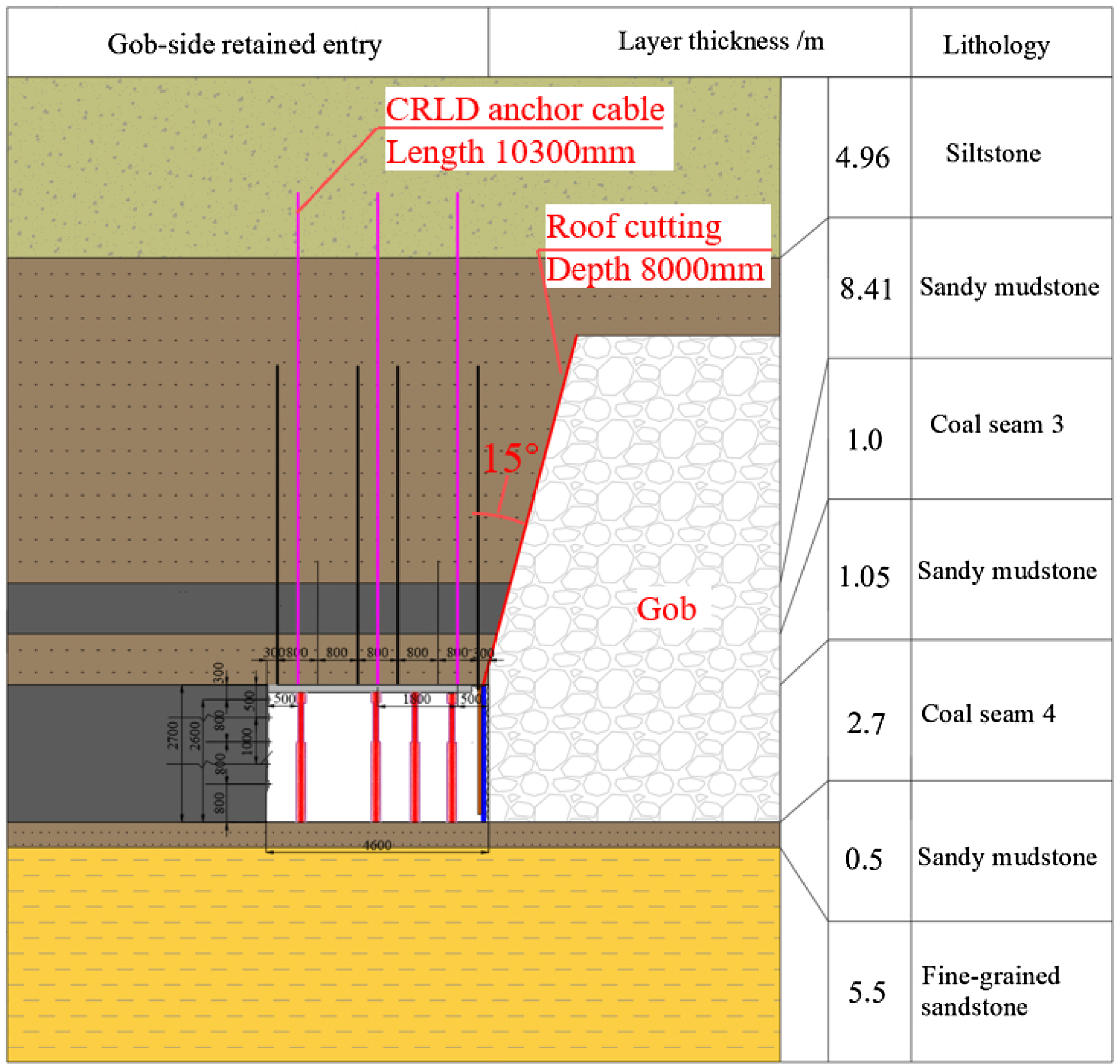
Directional roof cutting and support design.
Field effect of EAFRC
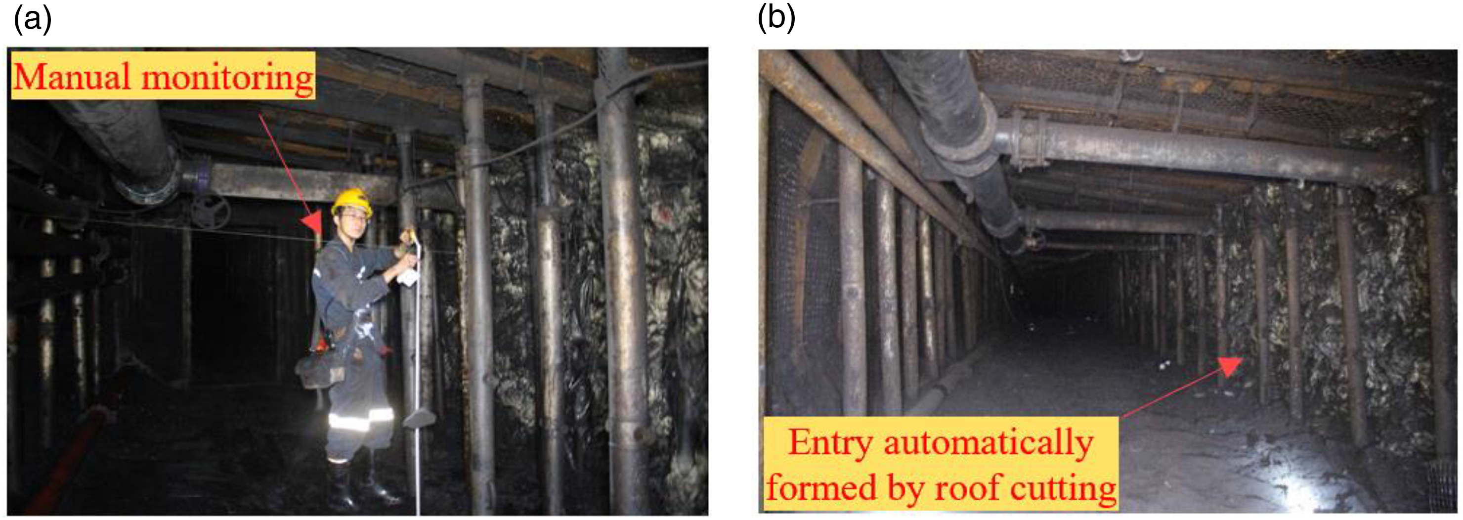
Monitoring equipment is arranged in the retained roadway to monitor the deformation of the roadway envelope. Through the monitoring of the deformation of the roadway surrounding rock and thus can determine the state of stability of the roadway surrounding rock. The monitoring method and the arrangement of measurement points are shown in Figure 16.
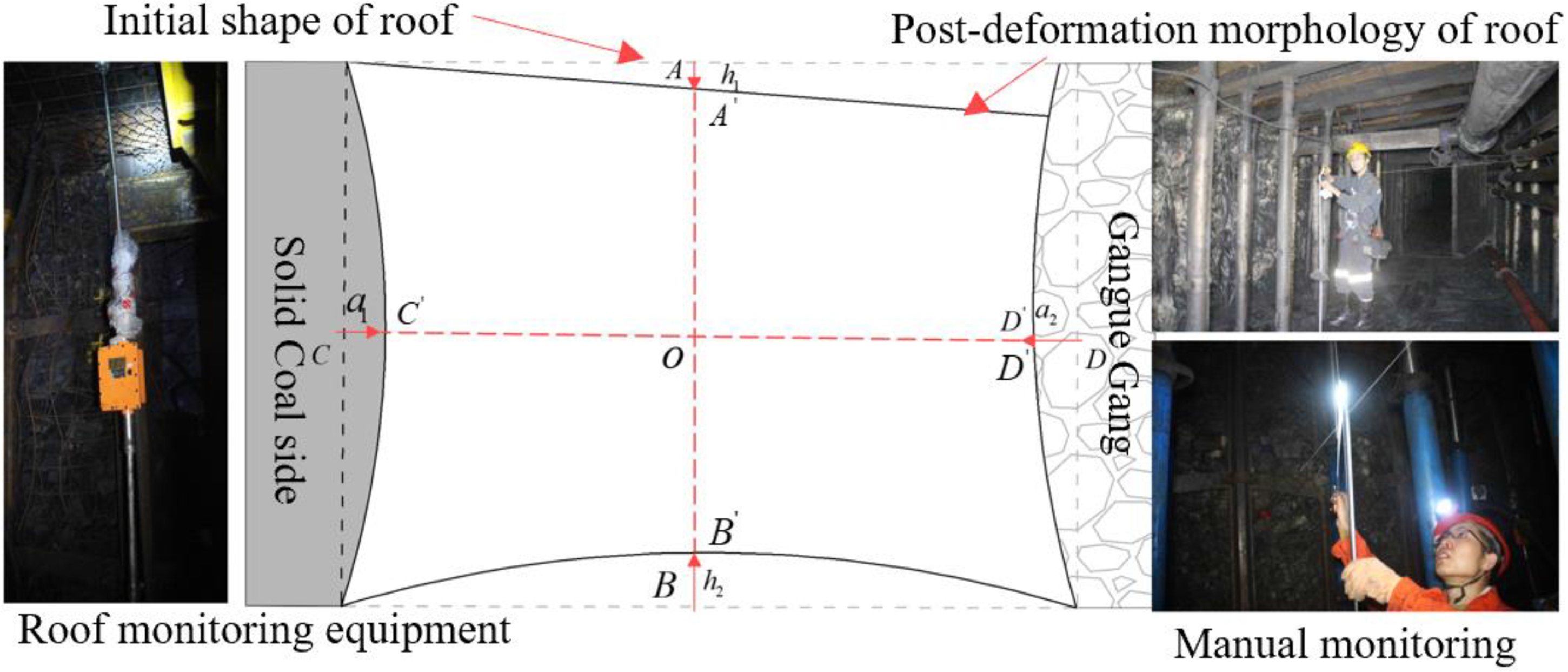
Arrangement of monitoring points for EAFRC.
The roof and bottom displacement deformation of retained roadway monitoring curve is shown in Figure 17. And from the analysis of Figure 17(a), it can be seen that the deformation of the surrounding rock of the roadway is obvious within 75 m of the lagging working face. And the deformation of the surrounding rock of the roof and bottom of the retained roadway tends to be stable after 180 m of the lagging working face. At the time of stabilization, the average sinkage of the roof of surrounding rock is 140 mm, the bottom drum is 170 mm, and the overall deformation of the surrounding rock is 310 mm. According to the on-site monitoring, the average deformation of the surrounding rock of the gob-side roadway during traditional mining is 1200 mm. The deformation of surrounding rock of EARFC in non-pillar mining is reduced by 74.1% compared with traditional mining.
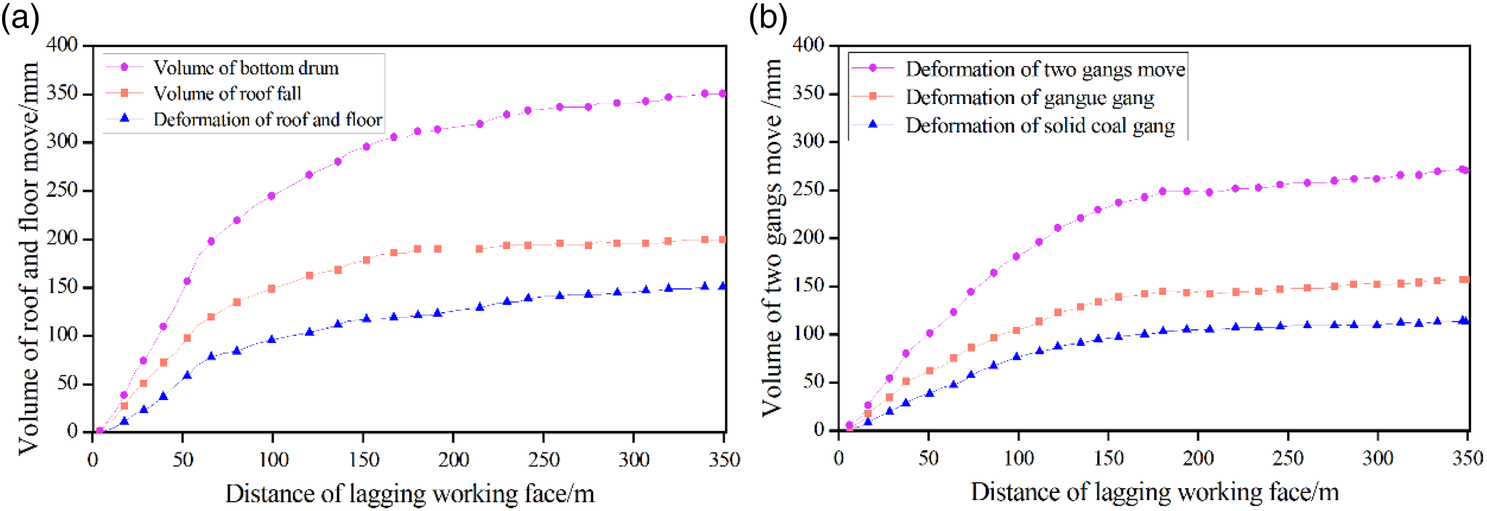
Displacement deformation law of surrounding rock of EAFRC: (a) roof and bottom displacement deformation law of retained roadway and (b) the displacement deformation law of the two gangs of the retained roadway.
The deformation monitoring curve of the two gangs of the retained roadway is shown in Figure 17(b), the roadway tends to be stable after 180 m of the working face. The deformation of the two gangs of the retained roadway at the time of stabilization is 253 mm, which can meet the requirements of the next working face for back mining. This also shows that the EAFRC method has achieved a good test effect, and the effect of the retained roadway on site is shown in Figure 18.
Surrounding rock deformation and gas control effect with EAFRC: (a) effect of surrounding rock deformation and control effect and (b) effect of gas control effect.
The gas concentration in the upper corner of the working face and the return air flow is monitored, and the gas concentration change pattern is shown in Figure 19. The gas concentration in the upper corner of the traditional mining is greater than that EAFRC. The average gas concentration in the upper corner during conventional mining is 0.64%, while the gas concentration in EAFRC is 0.30%, which is 53.3% lower than that during conventional mining. The peak gas concentration in the upper corner was 0.75% during traditional mining and 0.41% during EAFRC. The average gas concentration in the return air flow of the working face is 0.32%, which is 48.5% lower than the gas concentration in traditional mining. Therefore, using the method of EAFRC for mining can effectively reduce the gas concentration at the working face, prevent the gas from exceeding the limit and ensure the safe production of the mine.
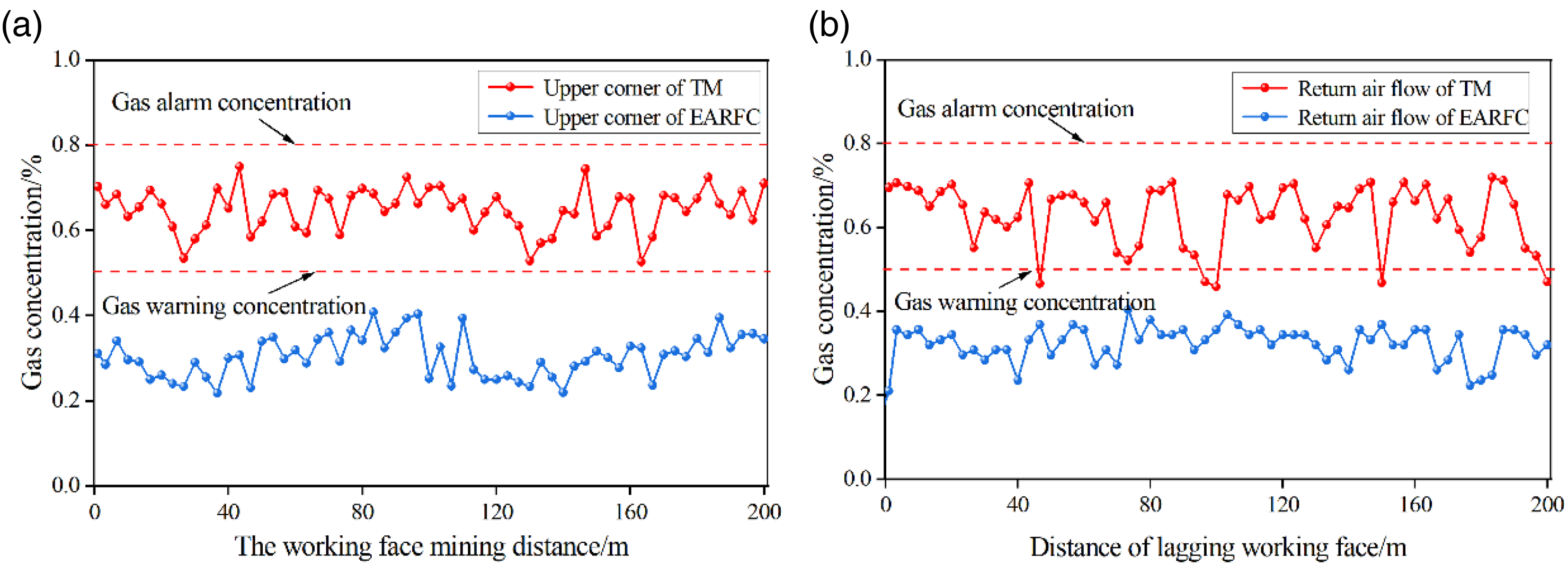
Gas concentration distribution characteristics of the working face: (a) gas concentration of upper corner and (b) gas concentration of return air flow.
Conclusion
Taking the 4303 working face of Shaqu coal mine as the field test area, the mine pressure of the surrounding rock and the gas migration law of gob-side entry retaining by roof cutting in gas coal seam were studied, and the main conclusions are as follows:
This paper aims at the problems of wasting coal resources by leaving coal pillars, serious deformation of surrounding rocks and excess-gas gas at working face of high gas coal seams in traditional mining method. The technology of EAFRC is proposed, and theoretically analyzes the model of roof cutting and pressure relief directional pre-splitting and the theoretical model of EAFRC in non-pillar mining. Numerical analysis models were established under different mining methods, and the mining pressure, surrounding rock deformation law and gas transport law in the mining area were analyzed by numerical simulation. Compared with the traditional mining, the pressure on the roof cutting side of the working face by non-pillar mining of EAFRC is 18.7 MPa, which is 24.2% lower than that on the non-cutting side in traditional mining. After adopting non-pillar mining of EAFRC, the ventilation mode of the working face is changed to Y-shaped ventilation, which solves the problem of excessive gas in the corners of the working face and improves the safety of the working face. Through on-site engineering tests, the EAFRC in non-pillar mining method has been verified. Realization of working face non-pillar mining effectively reduces the deformation of the surrounding rock of the retained entry, and the gas in the retained entry is controlled. Through the surrounding rock and gas monitoring results, it can be seen that the maximum amount of roof and bottom in the retained entry is 310 mm, and the average gas concentration in the formed roadway is 0.31%, which meets the needs of mine safety production. The successful application of this technology in the gas coal seam provides a reference for the application under similar mines.
Footnotes
Acknowledgements
This work is supported by the National Natural Science Foundation of China (No. 52204164), Fundamental Research Funds for the Central Universities (No. 2022XJSB03), and Young Elite Scientists Sponsorship Program by CAST (No. 2021QNRC001), which are gratefully acknowledged.
Declaration of conflicting interests
The authors declared no potential conflicts of interest with respect to the research, authorship and publication of this article.
Funding
The authors disclosed receipt of the following financial support for the research, authorship, and/or publication of this article: This work was supported by the Fundamental Research Funds for the Central Universities, Young Elite Scientists Sponsorship Program by CAST, National Natural Science Foundation of China, (grant number No. 2022XJSB03, No. 2021QNRC001, No. 52204164).