
Abstract
This article presents an integrated approach for theoretical analysis and numerical modeling to investigate the mechanism of roof presplitting and its reasonable parameters in the hard roof and longwall top-coal caving face. The test site is located in the city of Jinzhong, Shanxi Province, China. The theoretical analysis results indicated that when the presplitting angle remains constant, the tensile stress at the unpenetrated surface is approximately exponentially distributed with the presplitting height. When the presplitting height remains constant, the variation curve of tensile stress at the unpenetrated surface with the presplitting angle is parabolic. As the presplitting height increases, the presplitting angle required for the tensile stress at the unpenetrated face to exceed the ultimate tensile strength of limestone first increases and then decreases. The ground response of retained entry obtained with numerical modeling confirmed the theoretical analysis results. Meanwhile, numerical modeling results also showed that presplitting height affects the volume of the collapse gangues and the structure of the overlying strata above the retained entry. The presplitting angle is effective in reducing the frictional resistance between the collapse gangue and roof structure of retained entry. Moreover, based on the ground response of the retained entries, the reasonable parameters of the roof presplitting were determined at 17 m and 15°. The field application showed that reasonable roof presplitting parameters could achieve satisfactory effects at pressure relief and retained entry in the longwall top-coal caving panel. Furthermore, the proposed design principle of the roof presplitting technique can be applied to other projects.
Keywords
Introduction
The longwall top-coal caving (LTCC) mining method has been widely used in the underground coal mine in China (Mangal and Paul, 2016). During the mining process, as the working face advances, the overlying strata over the coal seam are disturbed by mining, which will cause serious roof activities such as subsidence, movement, fracture, and collapse (Bai et al., 2017). However, when the strength of rock strata immediately above the coal seam is higher, the strata will sink and overhang above the gob (Peng, 2017). Therefore, the larger overburden pressure caused by the suspended roof will be transmitted to the entries surrounding rock and coal pillars (He et al., 2012; Verma, 2014; Zhang et al., 2016). As a result, the abutment pressure on the coal pillar will increase, which will cause large deformation of the entries surrounding rock and coal pillars, such as coal rib spalling, pillar rib spalling, roof subsidence, and floor heave (Lu et al., 2015). Moreover, large-scale overhanging roof collapse in the gob will also cause rock bursts, wind bursts, or other catastrophic dynamic events (Shimada et al., 1998; Vakili and Hebblewhite, 2010). Therefore, the hard roof has been regarded as one of the reasons for the damage to equipment and casualties. In addition, due to the large mining height of the LTCC panel, the gob area is large, and the gob materials are difficult to support the overlying strata after the roof collapse. Thus, the overlying strata will form a cantilever beam structure in the dip direction of the mining panel (Zhang et al., 2015; Zhang et al., 2019). This will cause stress concentration of coal pillar and further lead to the large deformation of the roadway, especially when there is a thick and hard main roof immediately above the coal seam (Gao et al., 2013; Huang et al., 2018). Therefore, ensuring the timely collapse of the thick and hard main roof becomes the key to controlling the roadway deformation in the LTCC panel.
In 2008, Chinese scholar He proposed a cutting cantilever beam theory and finally formed a novel nonpillar coal mining technology with entry automatically retained by roof cutting (110 mining method) to solve the problem of large deformation of the roadway caused by the suspension of the thick and hard main roof (He et al., 2017; Tian et al., 2022; Wang et al., 2018b). This nonpillar coal mining technology first drills the blasthole on the gob-side roof of the roadway ahead of the working face. Second, the roof presplitting technology is used to generate a single fracture surface. Finally, the overlying strata behind the working face collapse along the fracture surface and form a gangue rib (He et al., 2021; Zhang et al., 2020b). Since the thick hard roof has been presplit ahead of the panel, after the panel is advanced, the overlying strata behind the panel will collapse and form a gangue rib (Manchao et al., 2003; Wang et al., 2018a). Moreover, due to using the expansion characteristics of collapsed gangue, the gob materials will fill the gob and support the overlying strata. Thereby, the retained entry is in the pressure relief areas (Guangchao et al., 2021; Zhang et al., 2011).
For the nonpillar coal mining method with entry automatically retained, Zhang et al. analyzed the cracked structural characteristics of the lateral roof and finally, concluded that the presplitting can improve the efficiency of the overlying strata collapse (He et al., 2007; Zhang et al., 2018). Zhang et al. proposed using energy-gathering blasting to cut the roof and protect the deep roadway from dynamic disasters, and finally, the pressure relief effect of roof cutting is verified through engineering applications (Zhang et al., 2020c; Zhang et al., 2020d). Guo et al. analyzed the fracturing mechanism of the retained entry roof and the plastic zone expansion law of the roadway rib (Guo et al., 2021). Zhu et al. studied the stability of the retained entry of the Hongjingta coal mine using a discrete fracture network model of UDEC software (Zhu et al., 2019). Gao et al. investigated the effects of directional roof split blasting (DRSB) on the stability of surrounding rock of retained entry at the meso- and macrolevels using the finite element method and finite difference method, respectively (Gao et al., 2019a). Chen et al. examined the key parameters of roof cutting in the nonpillar coal mining method and deduced the calculation formulas of roof cutting height and angle for the thin coal seams (Chen et al., 2019). Ma et al. studied the application of nonpillar coal mining method with entry automatically retained in deep medium-thick coal seams and analyzed the retained entry deformation law and control measures of the surrounding rock, and finally proposed the supporting measures (Ma et al., 2018a; Ma et al., 2018b).
The research results of the above scholars have greatly enriched the theoretical development and application of nonpillar coal mining methods with entry automatically retained. However, the previous research is mainly focused on the hard immediate roof in thin coal seams. There are few studies performed on LTCC panels in thick coal seams. Therefore, in order to reduce the roadway large deformation in the LTCC panel with the thick and hard main roof, this article takes the Shenlei Coal Mine 150202 LTCC panel as the research object. The mechanism of roof presplitting and its reasonable parameters are investigated through theoretical analysis, numerical simulation, and field experiments. Moreover, the relationship between the tensile stress on unpenetrated surfaces and presplitting parameters is discussed by establishing the mechanical model of overlying strata after roof presplitting. Finally, the reasonable parameters for roof presplitting of the LTCC face with the thick and hard main roof are determined. This research provides a reference for the application of roof presplitting and nonpillar coal mining methods with entry automatically retained in similar geological conditions.
Case analysis
Mining and geologic condition
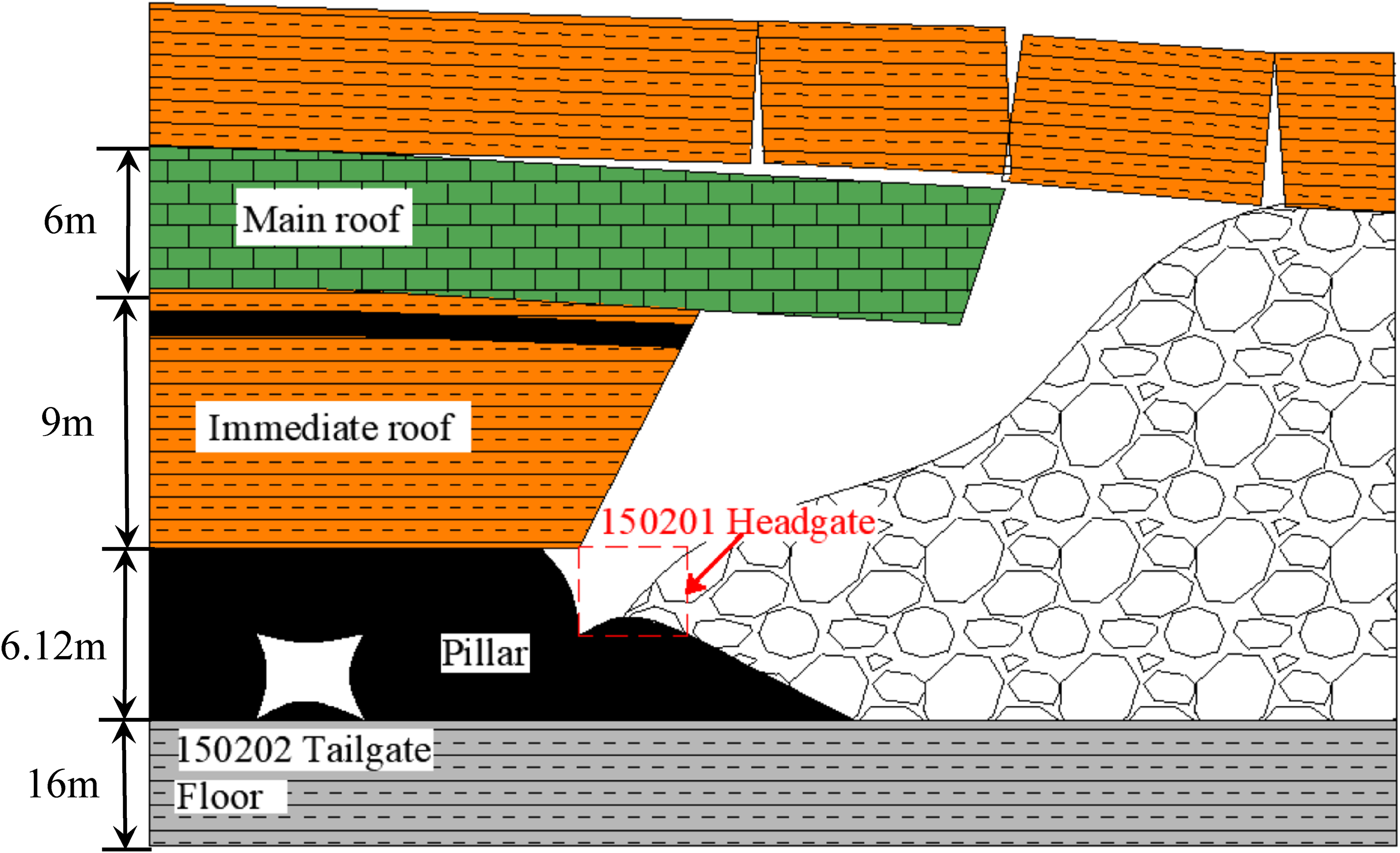
Sheilei Coal Mine is located in Heshun County, Jinzhong City, Shanxi Province, China, and is selected for case analysis, as shown in Figure 1(a). The study site is located at the headgate of the 150202 panel, with an average coverage depth of about 300 m. The currently mined coal seam is 15# coal seam. The thickness of the 15# coal seam is 4.3–7.6 m, with an average of 6.12 m. The average overburden depth of the 15# coal seam is 300 m. The average dip angle of the 15# coal seam is 8°. The LTCC mining method is used for 15# coal extracting, with a mining height of 2.4 m. The average mining rate of the LTCC face is 2.4 m/d. The strike and dip length of the 150202 LTCC working face are 1240 m and 150 m, respectively, as shown in Figure1(b). The roof strata above the15# coal seam are, in ascending order, mudstone (9 m), 14# coal seam (1 m), mudstone (1 m), limestone (6 m), and mudstone (12 m), and the strata below the 15# coal seam are, in descending order, mudstone (16 m) and sandstone (20 m), as shown in Figure 2.
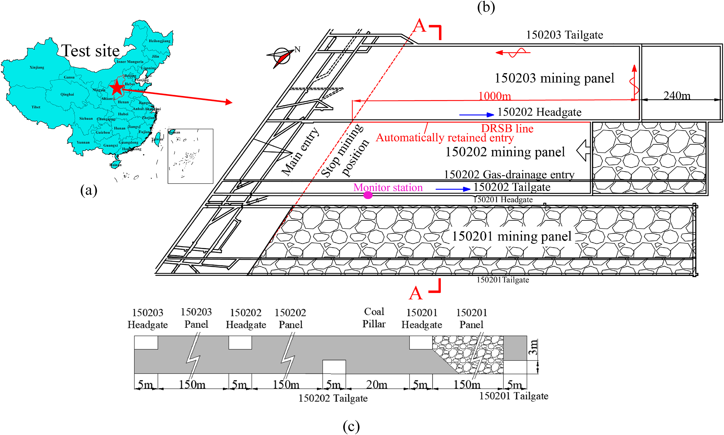
Mine location and panel layout of the mining panels: (a) mine location, (b) layout of the 150202 panel, and (c) A-A cross-section.
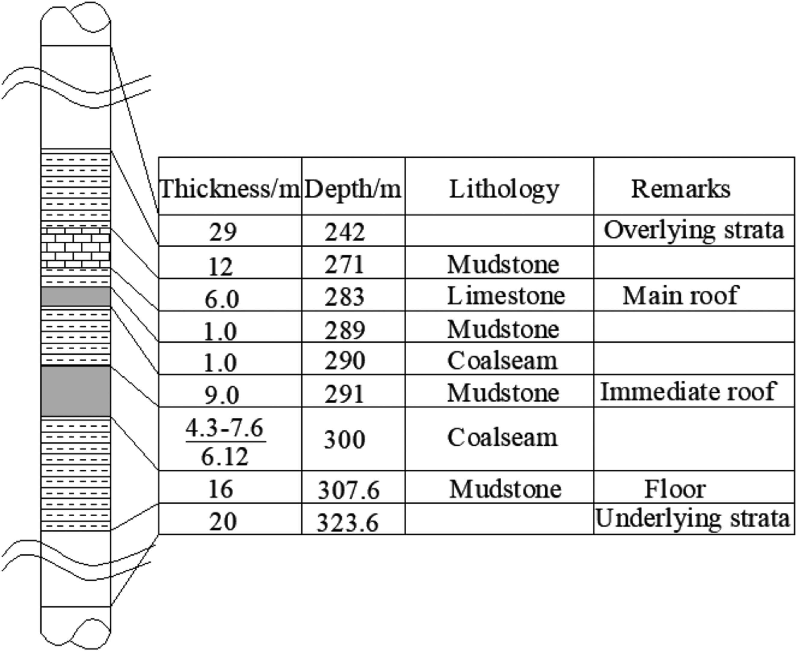
The generalized stratigraphic column of the test site.
The roadways are rectangular in shape, with 3.2 m × 5.2 m in cross-section. The 150201 and 150202 tailgates are excavated along the floor of the 15# coal seam, but the 150201 and 150202 headgates are excavated along the 15# coal roof, as shown in Figure 1(c). The roof is supported by the anchor cable of 18.9 mm × 8000 mm and threaded steel bolts of 18 mm × 2200 mm. The anchor cables are spaced by 1560 mm × 1600 mm. The threaded steel bolts are spaced by 700 mm × 800 mm. The two ribs are supported using fiber glass bolts of 22 mm × 1800 mm. The fiber glass bolts are spaced by 850 mm × 800 mm, as shown in Figure 3.
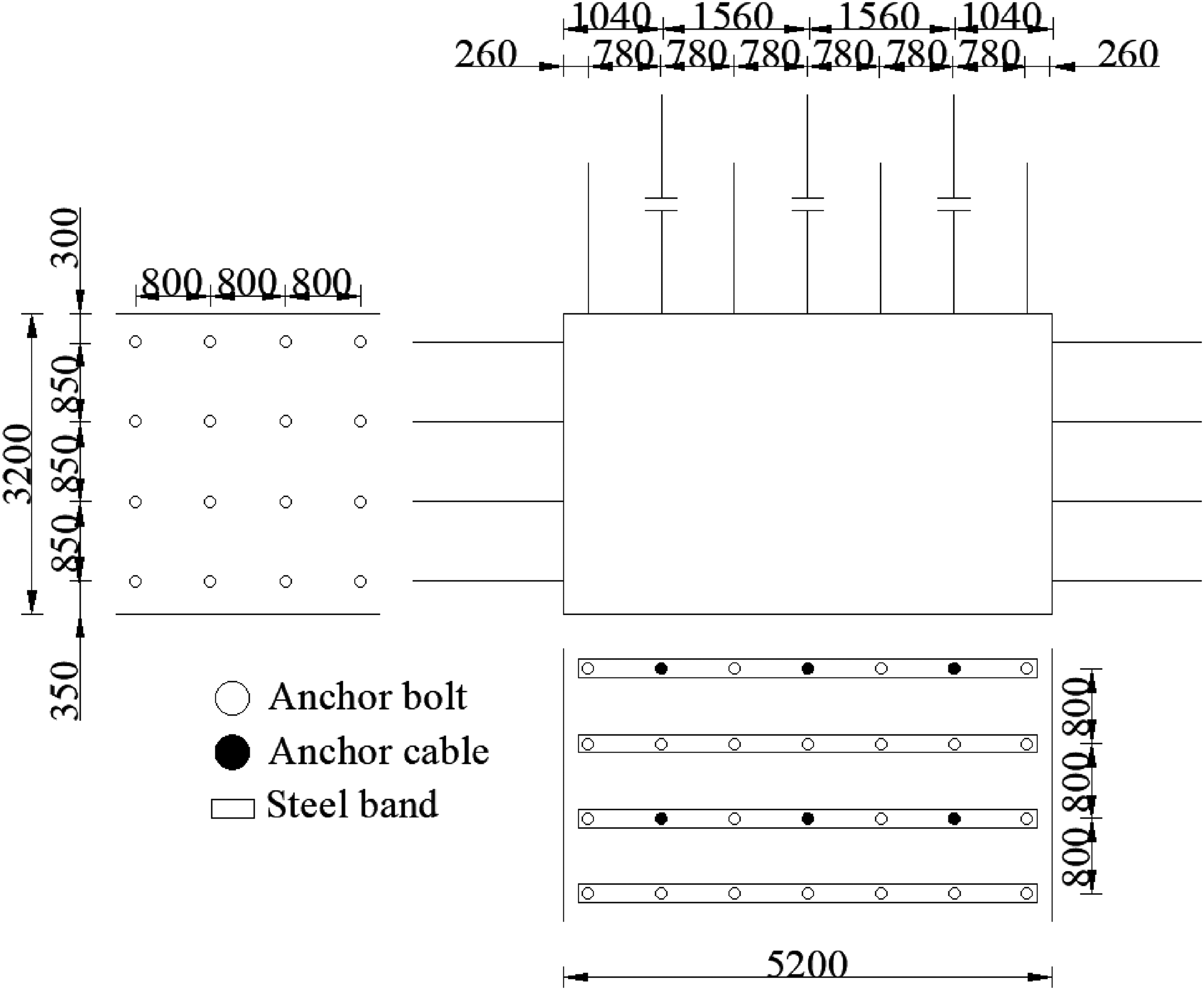
Roadway support design.
Roadway monitoring and deformation mechanism analysis
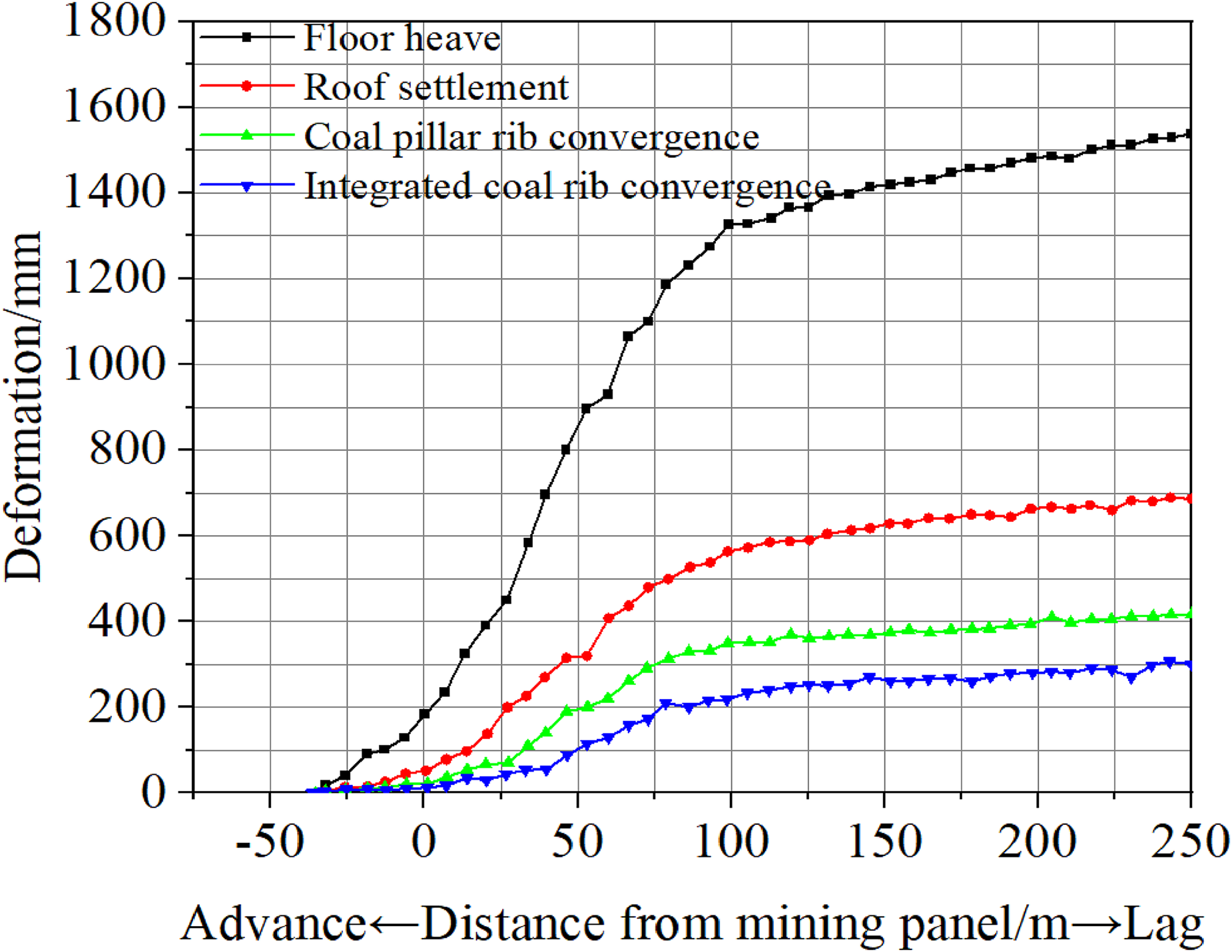
The field monitoring can provide quantitative data to evaluate the surrounding rock stability of the entries. When mining the 150201 LTCC panel, the observations of the severely deformed and fractured area of the 150202 tailgate behind the 150201 panel is shown in Figure 4. To study the deformation and failure mechanism of the roadway surrounding rock in the traditional LTCC mining method, we monitored the surface displacement of the 150202 tailgate adjacent to the 150201 LTCC panel, as shown in Figure 5. The monitoring results indicate the following: During the mining process of the 150201 panel, the convergences of surrounding rock of 150202 tailgate increase; the convergences decrease in the following order: floor heave > roof settlement > coal pillar rib convergence > integrated coal rib convergence. In addition, the maximum convergence between the roof and floor in the 150202 tailgate is 1788 mm and the maximum convergence between two ribs is 716 mm. The root cause of this ground response of entry is the property of the surrounding rocks (Bai and Tu, 2016; Jiang et al., 2019; Wu et al., 2021). Since the 150202 tailgate is excavated in a thick coal seam, the immediate floor and two ribs are composed of coal, the immediate roof is composed of mudstone, and the main roof is composed of limestone. Therefore, as the LTCC mining face advances, the stress release caused by the overhanging roof of the limestone will cause a significant floor heave and rib collapse (Gao et al., 2020; Verma and Singh, 2009), as shown in Figure 4(a) and (b).
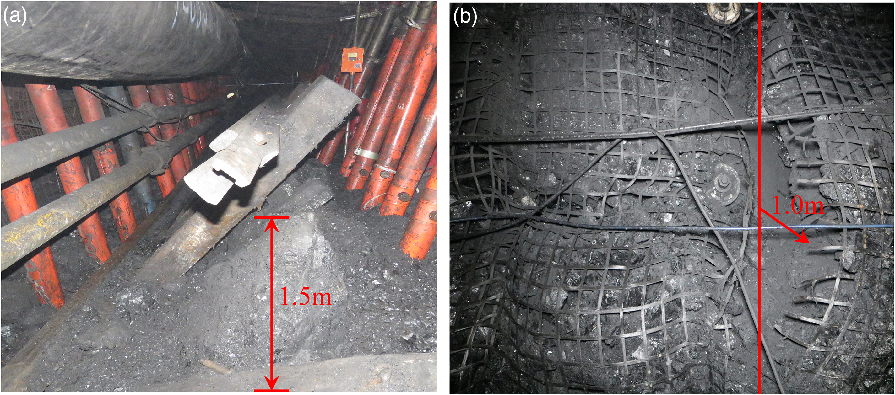
Field observations of severely deformed and fractured area: (a) floor heave and (b) rib spalling.
Monitored deformations of entry.
Control method
In 2021, to decrease the large deformation of the roadway, the nonpillar coal mining technology with entry automatically retained by roof presplitting is used in the 150202 LTCC panel of Shenlei Coal Mine (Figure 6). A schematic diagram of this nonpillar coal mining technology with entry automatically retained by roof presplitting is shown in Figure 7. First, the constant resistance and large deformation (CRLD) anchor cables and ordinary anchor cables are used to reinforce the support strengthen of entry roof and integrated coal rib, which effectively improves the self-supporting capacity and dynamic loading resistance of the surrounding rock of the roadway. Then the roof of the roadway ahead of the panel is presplitted, which not only cuts off the overhanging roof above the gob but also cuts off the roof stress transfer between the roadway and the gob, so that the retained entry is in the pressure relief area. Finally, behind the mining panel, the gob gangue collapses along the presplitting line and automatically forms a gangue rib, as shown in Figure 7.
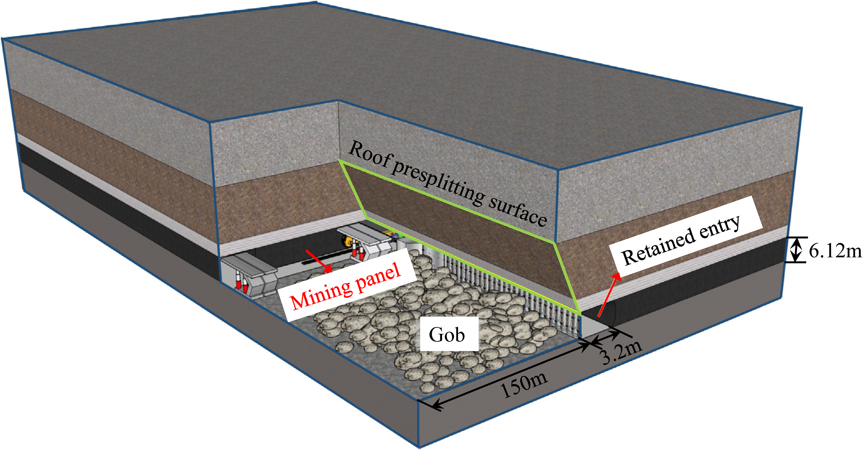
The 3D diagram of nonpillar coal mining technology with entry automatically retained by roof presplitting (Wang et al., 2020).
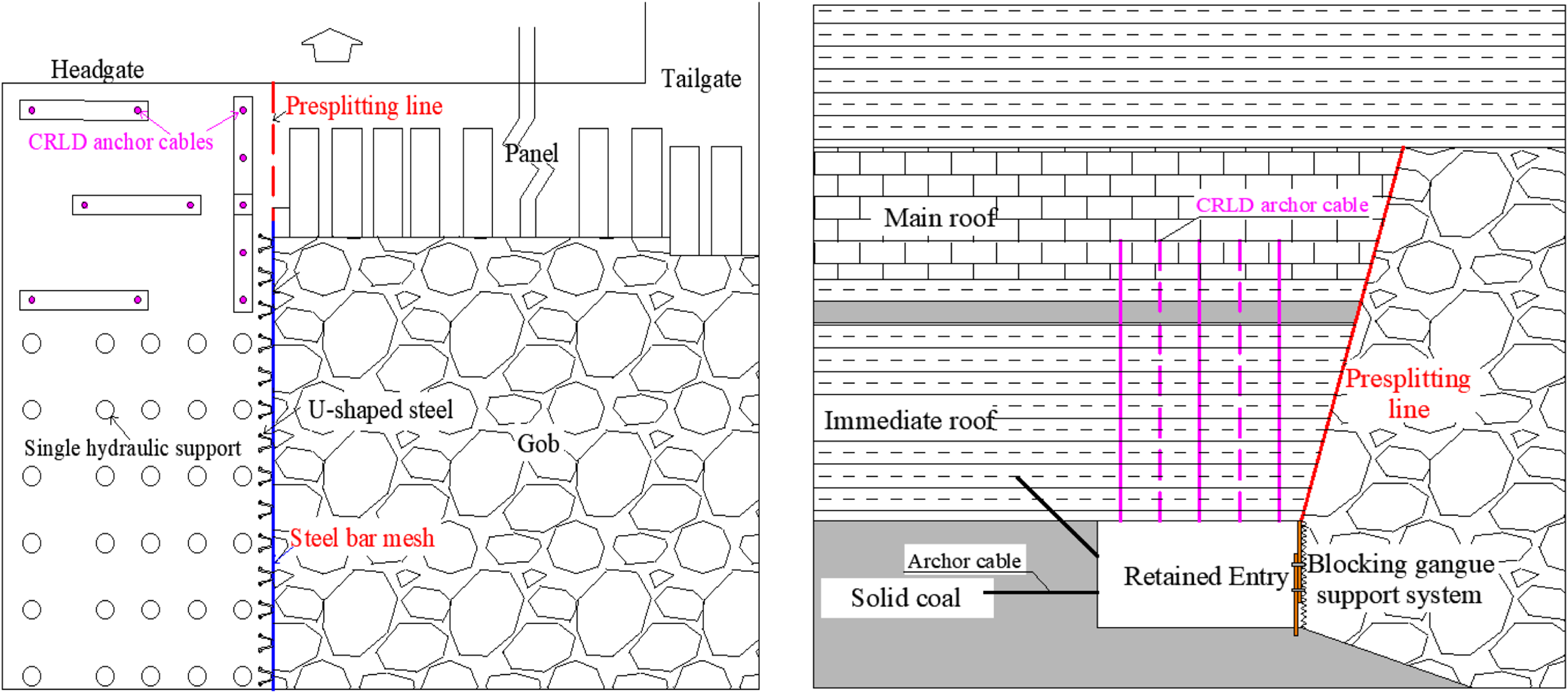
Schematic diagram of nonpillar coal mining technology with entry automatically retained by roof presplitting.
Mechanical model of roof presplitting
The most significant difference between the nonpillar coal mining technology with entry automatically retained by roof presplitting and the gob-side entry retaining technology is that the roof presplitting technology is used to optimize the roof structure of retained entry and the stress environment of retained entry (Gao et al., 2019b). Therefore, the roof presplitting technique is the foundation and key to the successful application of nonpillar coal mining technology. The position of the presplitting line is located at the boundary of the roadway roof. During the presplitting process, it not only separates the roof between the roadway and gob but also needs to ensure the integrity of the entry roof. Therefore, the bilateral cumulative tensile explosion (BCTE) technique is used to presplit the entry roof in nonpillar coal mining technology.
Principle of BCTE
Based on the characteristics of rock with higher compressive strength and lower tensile strength, the BCTE technique is invented to fracture the rock mass in a preset direction (Manchao et al., 2003; Zhang et al., 2020a). This technology refers to putting the explosive charge into the bilateral energy cumulative device (BECD) that has energy-accumulative effects in two preset directions at a certain angle. When the explosive is detonated in the BECD, under the guidance of the BECD, the detonation products are preferentially released from the energy cumulative holes, and an energy flow is formed. Finally, two symmetrical energy flow surfaces are formed in the design direction along the axial direction of the BECD after the energy flow is formed at each energy cumulative hole, as shown in Figure 8(a). In addition, because of energy flow, the blasthole will generate micro-cracks in the preset direction, and these cracks provide the space to guide and relieve pressure for the detonation products. When the compressive stress wave encounters the newly generated fracture surface, it will be reflected into a tensile wave, and a tensile stress concentration will be generated in the direction perpendicular to the fracture surface. Finally, the crack will extend in the presplitting direction and finally penetrate the adjacent blast hole because of the low tensile strength and high compressive strength character of the rock, as shown in Figure 8(b).
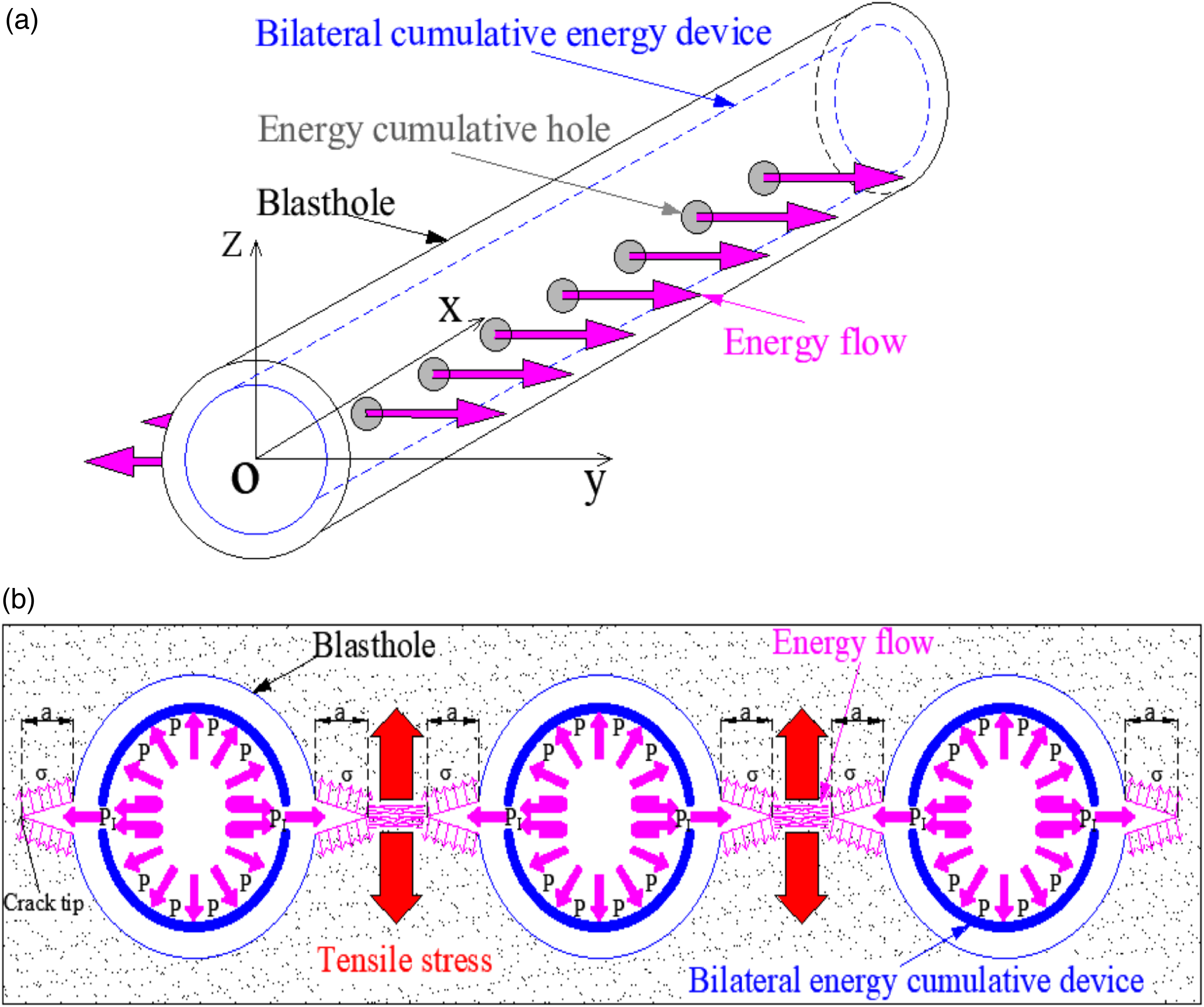
The mechanical model of directional roof presplit blasting: (a) energy-accumulative model and (b) energy-accumulative model of multihole in zoy plane.
Mechanical model of overlying strata after roof presplitting entry retaining
Figure 9 shows the mechanical model of overlying strata in the LTCC mining method. It can be seen from Figure 9 that after the LTCC mining panel with the thick and hard main roof is extracted, the immediate roof collapses rapidly. The thick and hard main roof forms a cantilever beam structure in the dip direction of the working face. Moreover, since the gob material is difficult to support the overlying strata, the load of the overlying strata and the cantilever beam structure cause a stress concentration in the coal pillar, which seriously affects the stability of the surrounding rock of the adjacent roadway.
Mechanical model of overlying strata in longwall top-coal caving (LTCC) mining method.
The roof presplitting technique could cut off the length of the cantilever beam formed by the thick and hard main roof and reduce the stress transmission effect of the cantilever beam structure on the overlying strata load, and finally, ensure the stability of surrounding rocks. Therefore, the key to the success of the application of the nonpillar coal mining technology with entry automatically retained by roof presplitting is to determine the reasonable roof presplitting parameters (presplitting height and presplitting angle). The presplitting height and presplitting angle have different functions in the nonpillar coal mining technology with entry automatically retained by roof presplitting. (1) The function of the presplitting height is to increase the height of the caving zone so that the collapse gangue can fill the gob and support the overlying strata.Hence,the retained entry is in the pressure relief area. In addition, the roof presplitting can also cut off the connection between the roofs.Therefore, the thick hard roof collapse along the presplitting line, which prevent the roof from forming a long cantilever beam structure and reduce the roadway's large deformation due to stress concentration. (2) Rock mass is an inhomogeneous and anisotropic material. There are many joints and fissures inside. It is difficult to produce a flat and smooth presplitting surface after blasting. Therefore, a reasonable presplitting angle is effective in reducing the frictional resistance between the collapse gangue and roof structure of retained entry.
To study the effect of presplitting parameters (presplitting height and presplitting angle) on the stability control of the surrounding rock of retaining entry, a mechanical model of overlying strata after roof presplitting is established according to the geological conditions of Shenlei Coal Mine 150202 LTCC mining panel, as shown in Figure 10.
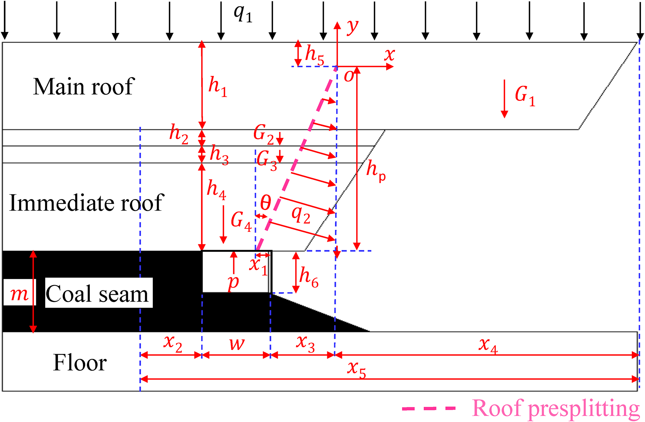
Mechanical model of overlying strata after roof presplitting.
It can be seen from Figure 10 that to ensure the easy collapse of the cantilever beam structure and considering that the tensile strength of the rock mass is less than the compressive strength and shear strength, the tensile stress on the unpenetrated surface (h5) of the main roof should be greater than its tensile strength.

where σ is the tensile stress of the unpenetrated surface, MPa and στ is the tensile strength of the main roof, MPa.
For the tensile stress σ at the unpenetrated surface, take the point o at the end of the presplitting surface as the origin, then the formula for calculating the tensile stress at the origin is as follows:

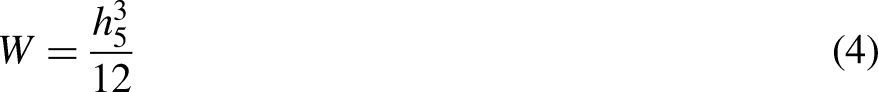
where M is the bending moment at the unpenetrated surface, N·m and W is the flexural coefficient at the unpenetrated surface.
The bending moment at the unpenetrated surface M and flexural coefficient at the unpenetrated surface can be obtained as follows (Guo et al., 2016):

where q1 is a load of overlying strata, N/m; q2 is the force on the left side of the presplitting surface to the right side, N; ρ is the density of the main roof rock strata, kg/m3; x4 is the horizontal distance from the end of the cantilever beam to point o, m; hp is the height of presplitting line, m; h1 is the thickness of the main roof, m; h5 is the vertical distance between the top of the unpenetrating surface and the top of the main roof, m; and θ is the angle of presplitting line, °.
The h5 and x4 are as follows:


where h2 and h3 are the thickness of the interlayer between the immediate roof and main roof, respectively, m; h4 is the thickness of the immediate roof, m; x1 is the horizontal distance from the starting position of the presplitting line to the entry rib, m; x2 is the width of the limit equilibrium zone, m; w is the width of the entry, m; and x3 is the horizontal distance from the end of the presplitting line to the entry rib, m.
The x2 is as follows:
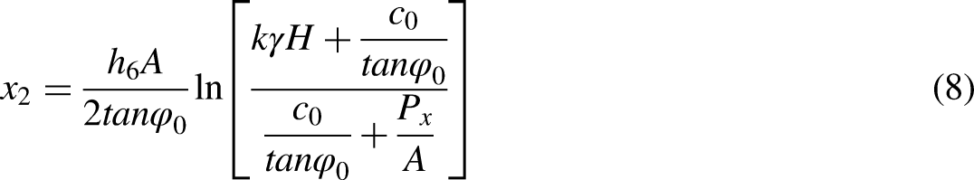
where h6 is the height of the entry, m; A is the coefficient of lateral pressure; φ0 is the friction angle, °; k is the stress concentration factor; γ is the unit weight, KN/m3; H is the buried depth of the roadway, m; c0 is the cohesion of coal-rock interface, MPa; and Px is the support resistance of coal rib, MPa.
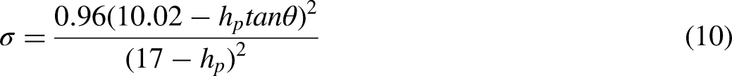
Equations (3) to (7) can be used to obtain the tensile stress σ at the unpenetrated surface, as shown in equation (9).

According to the geological conditions of Shenlei Coal Mine 150202 LTCC mining panel, h1 = 6 m, h2 = 1 m, h3 = 1 m, h4 = 9 m, x1 = 0.2 m, w = 5 m, q1 = 0.16 MPa, and ρ = 2700 kg/m3, according to the literature (Ying-Fu et al., 2012), x5 = 20.83 m, and x2 = 6.01 m. Because the roof presplitting technique is used to generate the presplitting surface at the engineering application so q2 = 0 N. Substituting the above parameters into equation (9), the relationship between the tensile stress at the unpenetrated surface and the presplitting height (hp) and presplitting angle (θ) can be determined as follows:
Sensitivity analysis
To understand the effect of presplitting parameters variation on the tensile stress of the unpenetrated surface, the sensitivity of the tensile stress to the presplitting parameters included in the proposed mechanical model was analyzed. Sensitivity analysis was performed with one parameter as a variable and the other parameters as constants. Figure 11 shows the relationship curves between the tensile stress at the unpenetrated surface and the presplitting parameters including presplitting height and presplitting angle.
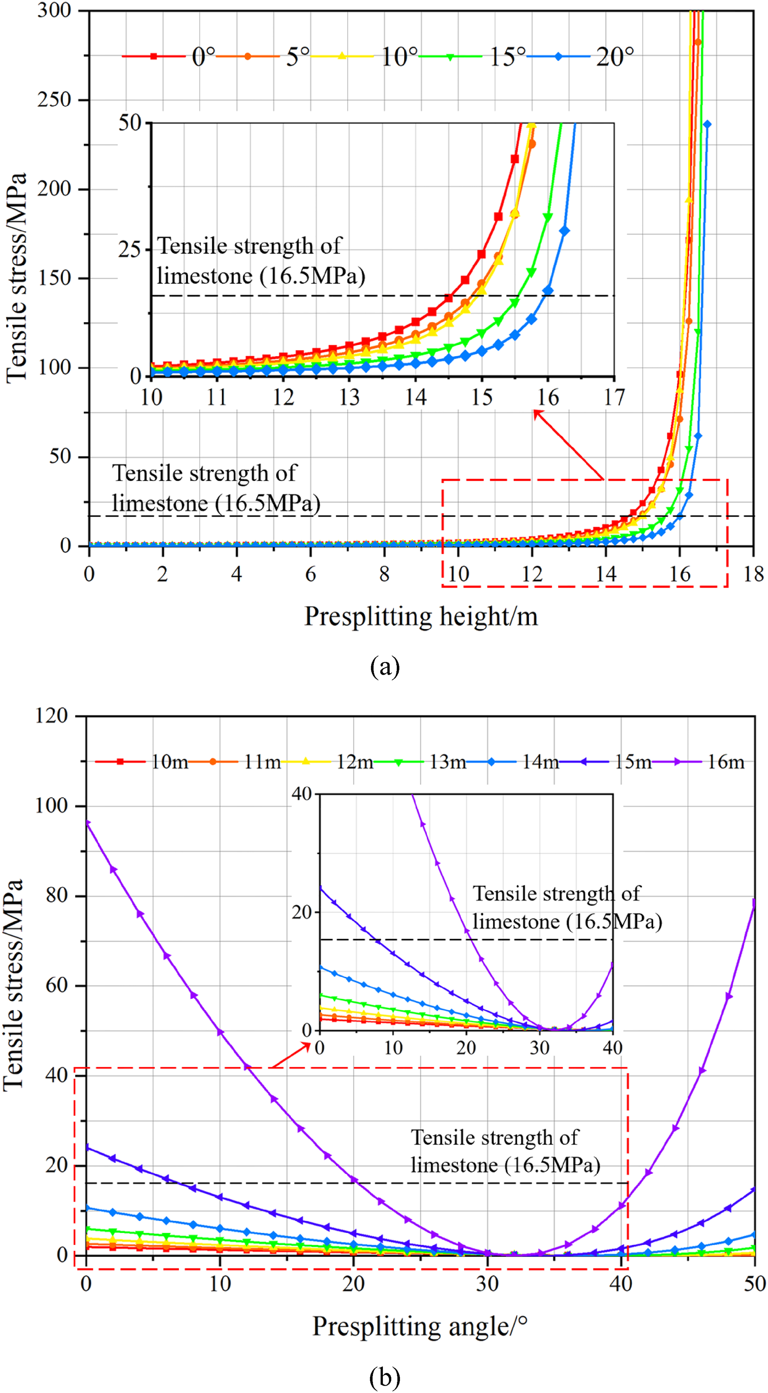
The relationship curves between the tensile stress at the unpenetrated surface and the presplitting parameters: (a) the effect of presplitting height on tensile stress and (b) the effect of presplitting angle on tensile stress.
According to the stress distribution on the beam with the rectangular section, the tensile stress of the unpenetrated surface is obtained. The main factors affecting the tensile stress at the unpenetrated surface are determined based on equation (10). Therefore, the factors are as follows: tensile stress of the unpenetrated surface (σ), presplitting height (hp), and presplitting angle (θ). Equation (10) fits curves with different parameters to analyze the relationship between σ, hp, and θ, respectively. Variations of the tensile stress at the unpenetrated surface of nonpillar coal mining technology with entry automatically retained by roof presplitting against the presplitting height and presplitting angle are shown in Figure 11.
If other parameters remain constant, the tensile stress at the unpenetrated surface is approximately exponentially distributed with the presplitting height, as shown in Figure 11(a). The tensile stress increases with the increase of the presplitting height, and the growth rate is gradually accelerated. As the presplitting angle increases, the presplitting height required for the tensile stress at the unpenetrated face to exceed the ultimate tensile strength of limestone also increases gradually. When the presplitting angles are 0°, 5°, 10°, 15°, and 20°, respectively, after the presplitting height exceeds 13.7 m, 14 m, 14 m, 15 m, and 15.6 m, the cantilever beam structure formed by the main roof will collapse smoothly under the action of its own weight, the load of the overlying strata and the mining disturbance.
If other parameters remain constant, the variation curve of tensile stress at the unpenetrated surface with the presplitting angle is parabolic, as shown in Figure 11(b). As the presplitting height increases, the presplitting angle required for the tensile stress at the unpenetrated face to exceed the ultimate tensile strength of limestone first increases and then decreases. When the presplitting height is 15 m, the required presplitting angle range is 0°<θ<8° or 50°<θ<90°; When the presplitting height is 16 m, the required presplitting angle range is 0°<θ<20° or 43°<θ<90°. The function of the presplitting angle in the process of roof presplitting is to reduce the friction resistance on the roof of the retained entry during the collapse of the cantilever beam structure and facilitate construction. Therefore, the key to the roof presplitting technique is to determine a reasonable presplitting height and a reasonable presplitting angle.
Numerical studies of roof presplitting parameter
To elucidate the effects of roof presplitting on the ground response of entries in the hard roof and LTCC face, two numerical test schemes with different roof presplitting heights and angles are designed to study the effect of presplitting height and presplitting angle on the deformation and stress distribution of the surrounding rock of the retained entry.
Schemes design
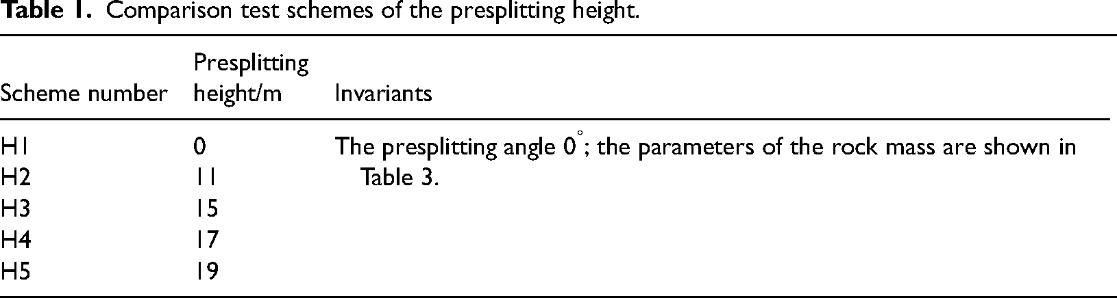
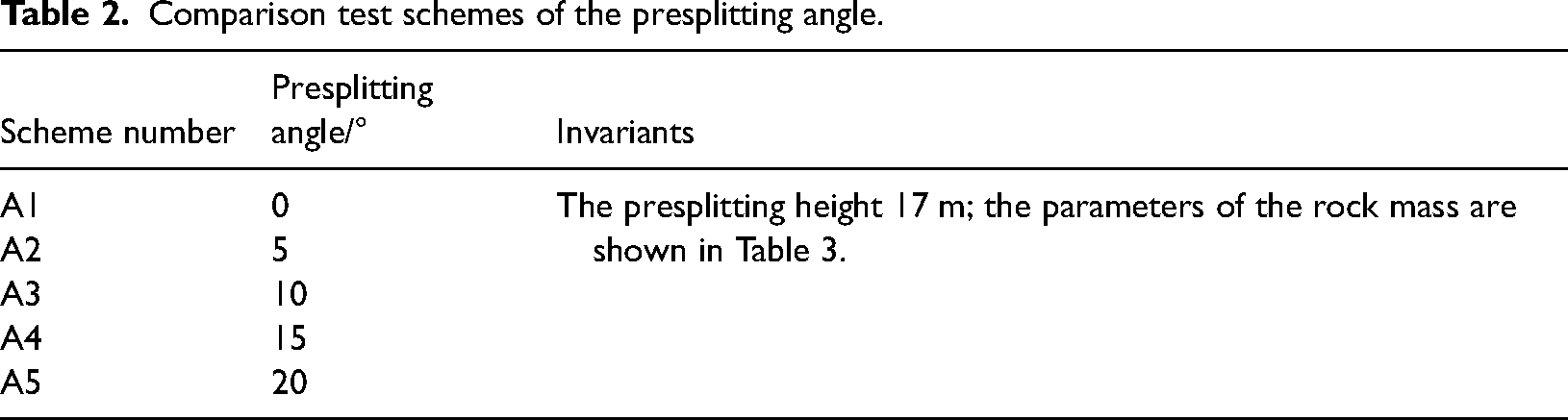
In numerical schemes, the cross-section dimensions and support scheme of the 150202 headgate of Shenlei Coal Mine are taken as invariants. Furthermore, two numerical test schemes are designed with different roof presplitting heights and angles. The comparison test scheme types I and II use bolt-mesh-cable support technology. The scheme numbers H1, H2, H3, H4, and H5 in scheme type I correspond to presplitting heights of 0 m, 11 m, 15 m, 17 m, and 17 m, respectively. The scheme numbers A1, A2, A3, A4, and A5 in scheme type II correspond to presplitting angles of 0°, 5°, 10°, 15°, and 20°, respectively.
Scheme type I
Taking presplitting height as a variable and other parameters remaining constant, we design five comparative test schemes (H1 to H5). The details of the scheme type I are shown in Table 1.
Comparison test schemes of the presplitting height.
Scheme type II
Taking presplitting angle as a variable and other parameters remaining constant, we design five comparative test schemes (A1 to A5). The details of the scheme II are shown in Table 2.
Comparison test schemes of the presplitting angle.
Numerical modeling and evaluation index
Model configuration
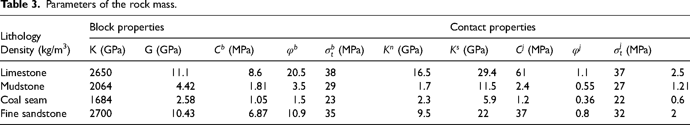
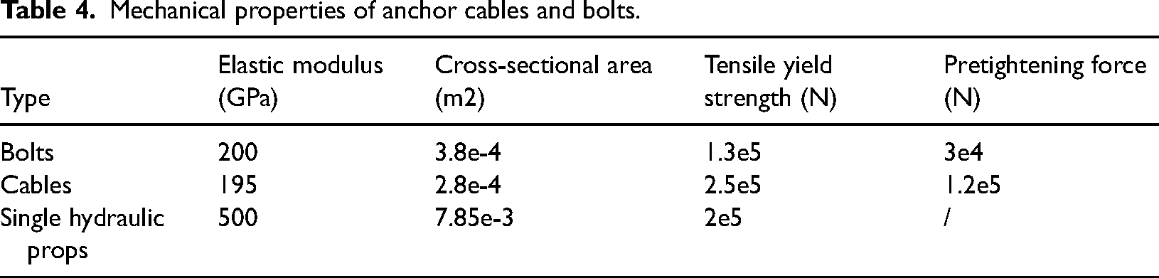
One of the key technical principles of nonpillar mining is to use the expansion characteristics of the collapsed gangue to form a stable support structure. The collapse and deformation of the overlying strata are vitally important for the stability of the roadway surrounding rock. Therefore, the current calculation software such as the finite element method and finite difference method can no longer meet the requirements of this article for the research on the mechanism of roof presplitting in nonpillar coal mining technology. Hence, in this subsection, 3DEC numerical simulation software is used to verify the theoretical analysis results above and investigate the influence of roof presplitting on the ground response of entries. According to the geological conditions of the 150202 LTCC panel, a numerical model of 250 m × 150 m × 100 m (length × width × height) was established, as shown in Figure 12(a) and (b). To simplify the calculation of the model, half of the inclination length of the panel is selected to build the model according to the principle of symmetry. In the numerical model, the inclination length of the 150202 LTCC working face is 75 m, the strike length is 250 m, the mining height is 7.5 m, and the dimension of the roadway is 5.0 m × 3.0 m. A vertical load of 6.48 MPa was applied to the upper boundary to simulate overburden pressure. The static pressure coefficients along the x and y axes are set to 0.8 and 1.2, respectively. The horizontal and bottom boundaries are roller constraints (Zhang, 2016). The bottom boundary is vertically fixed, the front, back, left, and right boundaries are horizontally fixed, and the top boundary is free. The Mohr–Coulomb constitutive model is used to simulate the surrounding rock. Comparing the experimental and simulated test results of the uniaxial compression test, the physical and mechanical parameters of rock mass are shown in Table 3 (Chaudhary et al., 2021; Wang et al., 2016; Zhenqian, 2016). In addition, the mechanical parameters of the joint are determined according to the same strata of “Qinshui coalfield” from previous research (Sitharam et al., 2007). A comparing the experimental and simulated stress–strain curves for limestone, mudstone, and coal specimens is shown in Figure 13(a), (b) and (c). The experimental setup used for testing the stress–strain of roof rock samples is Hydraulic Pressure Testing Machine which type is XTYE-2000. The cable structure element is used to model the cables and bolts and the mechanical parameters of cables and bolts are shown in Table 4 (Guangchao et al., 2021). The stress monitoring points and displacement monitoring points are installed on the roof, floor, and integrated coal side of the roadway, which are denoted as Rs, Sa, and Ce, where s = 1–21, a = 1–21, and e = 1–2. The distance between two adjacent stress monitoring points Rs is 1.5 m, and the distance between two adjacent stress monitoring points Sa is 2 m.
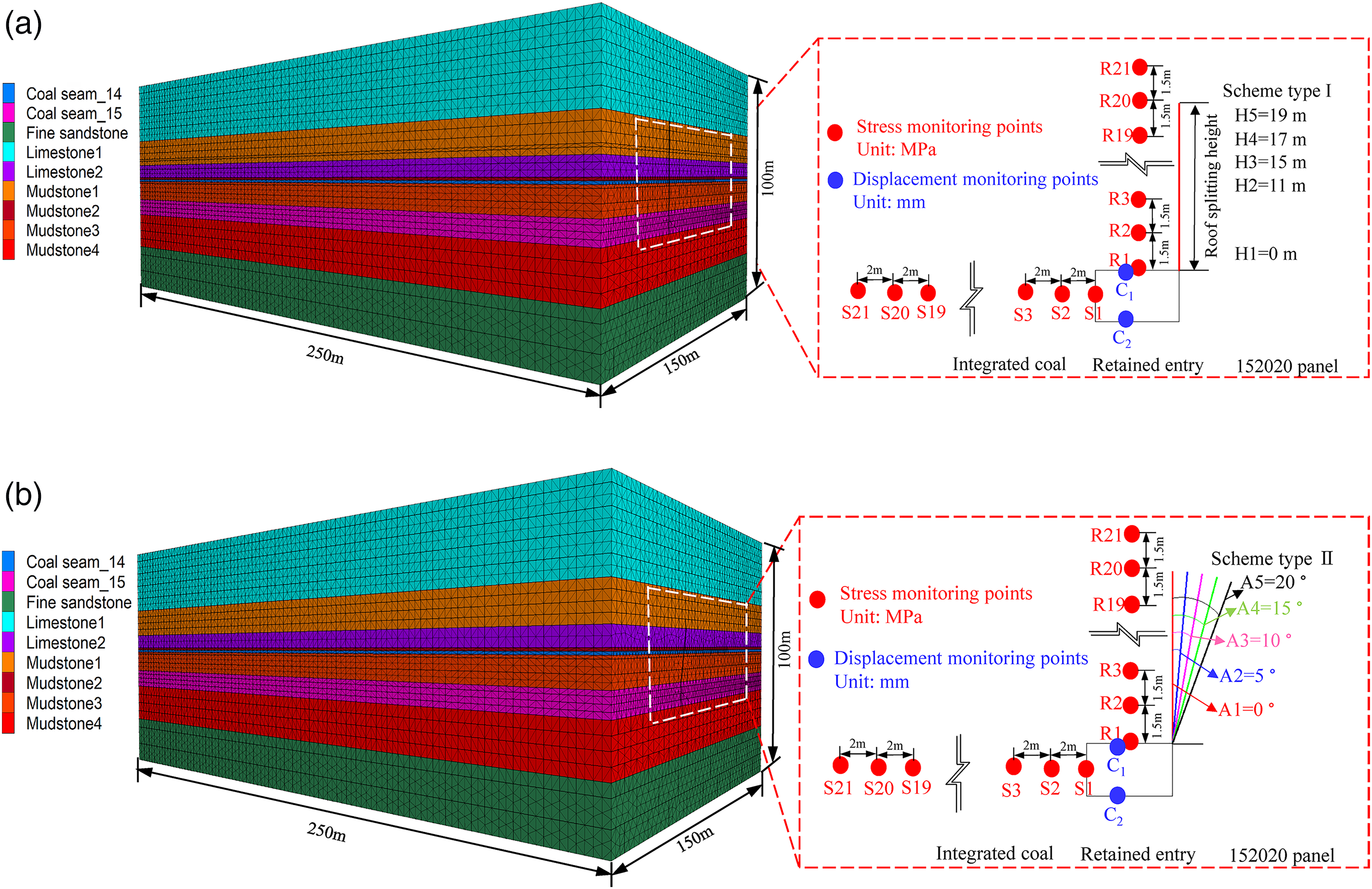
The diagram of the simulation scheme and monitoring scheme: (a) simulation of scheme type I and (b) simulation of scheme type II.
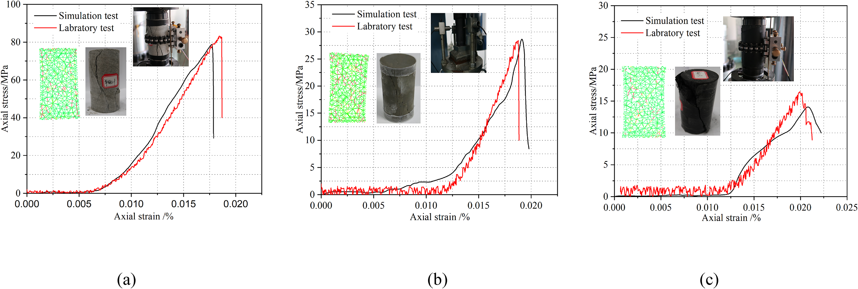
Comparing the experimental and simulated stress–strain curves for (a) limestone, (b) mudstone, and (c) coal specimens.
Parameters of the rock mass.
Mechanical properties of anchor cables and bolts.
Establishment of evaluation index
To compare and analyze the influence of roof presplitting on the ground response of retained entries, three evaluation metrics: entry deformation control rate ηd−xi, the peak abutment pressure decrease rate in roadway integrated coal rib ηa−xi, and stress decrease rate of roadway roof ηf−xi are proposed
(1) Entry deformation control rate (ηd−xi): (2) The peak abutment pressure decrease rate in roadway integrated coal rib (ηa−xi): (3) Stress decrease rate of roadway roof (ηf−xi):
where Cd−L is the convergence of the roof and floor in the roadway of LTCC face, m; Cd−xi is the convergence of the roof and floor in the roadway of scheme XI, x = H and A; i = 1, 2, 3, 4, 5 m(e.g. x = H and x = 1 represent the convergence of the roof and floor in the roadway of scheme H1).

where Va−L is the peak abutment pressure on the integrated coal rib side of roadway in the LTCC face, MPa; Va−xi is the peak abutment pressure on the integrated coal rib side of roadway in scheme XI, x = H and A; i = 1, 2, 3, 4, and 5 MPa.

where Vf−L is the vertical stress of the roadway roof in the LTCC face, MPa; Vf−xi is the vertical stress in the retained entry roof of scheme XI, x = H and A; i = 1, 2, 3, 4, and 5 MPa.
The ηd−xi represents the roadway surrounding rock deformation control rate compared with the scheme XI and the original LTCC mining method. The larger ηd−xi is, the pressure relief effect is more obvious, and the control effect on large deformation of surrounding rock is much better. The ηa−xi represents the peak abutment pressure decrease rate of roadway integrated coal rib compared with the scheme XI and the original LTCC mining method. With the higher ηa−xi value, the pressure relief effect of the roof presplitting technique is more obvious. The ηf−xi represents the roof stress decrease rate in the retained entry of scheme XI compared with the original LTCC mining method. With the larger ηf−xi value, the pressure relief effect of the roof presplitting technique is more obvious.
Result analysis
Results analysis of scheme type I
The presplitting height is taken as the independent variable, and the scheme numbers H1 to H5 in scheme type I represent the presplitting heights of 0, 11, 15, 17, and 19 m, respectively. Figure 14 shows the convergence of the roof and floor of retained entry, the abutment pressure on the integrated coal rib, the roof stress of retained entry, and the stress and deformation evaluation index, respectively.
Convergence of roof and floor:
By comparing and analyzing the convergence of roof and floor with different presplitting heights, it can be concluded that: When the presplitting heights are 0, 11, 15, 17, and 19 m, the corresponding convergence of roof and floor in the retained entry are 599.31, 551.64, 531.25, 505.70, and 500.74 mm, and the entry deformation control rates (ηd−xi) are 0, 7.95%, 11.36%, 15.62%, and 16.45% respectively, as shown in Figure 14(a) and (d). With the roof presplitting height increasing, the convergence of the roof and floor gradually decreases, which is conducive to retaining the entry. Reasonable roof presplitting height analysis: when the presplitting height increase from 0 to 17 m, the convergence of roof and floor in the retained entry reduces significantly. However, when the presplitting height increases from 17 to 19 m, the magnitude of the roof and floor convergence variation is small, at 0.98%. Increasing the presplitting height does not have a significant effect on the convergence of the roof and floor after the presplitting height reaches a certain value. The abutment pressures:
By comparing and analyzing the side abutment pressure with different presplitting heights, it can be concluded that: when the presplitting heights are 0, 11, 15, 17, and 19 m, the corresponding peak abutment pressures on the integrated coal rib are 22.15, 19.93, 19.19, 18.83, and 18.63 MPa, and the peak abutment pressure decrease rates (ηa−xi) are 0, 10.02%, 13.36%, 14.99%, and 15.89%, respectively, as shown in Figure 14(b) and (d). As the presplitting height increases, the peak abutment pressure of the integrated coal rib gradually decreases, which is conducive to retaining the entry. Reasonable presplitting height analysis: when the presplitting height increase from 0 to 17 m, the peak abutment pressure of integrated coal rib reduces significantly. However, when the presplitting height increases from 17 to 19 m, the magnitude of peak abutment pressure variation is small, at 1.06%. Increasing the presplitting height does not have a significant effect on the peak abutment pressure after the presplitting height reaches a certain value. In addition, as the presplitting height increases, the construction cost and construction difficulty of roof presplitting will also increase. The roof stresses:
By comparing and analyzing the roof stress with different presplitting heights, it can be concluded that: when the presplitting heights are 0, 11, 15, 17, and 19 m, the corresponding average roof stresses of the retained entry are 16.02, 15.56, 14.65, 13.83 and 13.15 MPa. The roof stress decrease rates (ηf−xi) are 0, 2.87%, 8.55%, 13.67%, and 15.92%, respectively, as shown in Figure 14(c) and (d). As the presplitting height increases, the average roof stresses gradually decrease and the pressure relief effect of presplitting is more obvious. Reasonable presplitting height analysis: when the presplitting height increases from 0 to 17 m, the average roof stress reduces significantly. However, when the presplitting height increases from 17 to 19 m, the magnitude of average roof stress variation are small, at 4.92%. Increasing the roof presplitting height does not have a significant effect on the average roof stress after the presplitting height reaches a certain value.
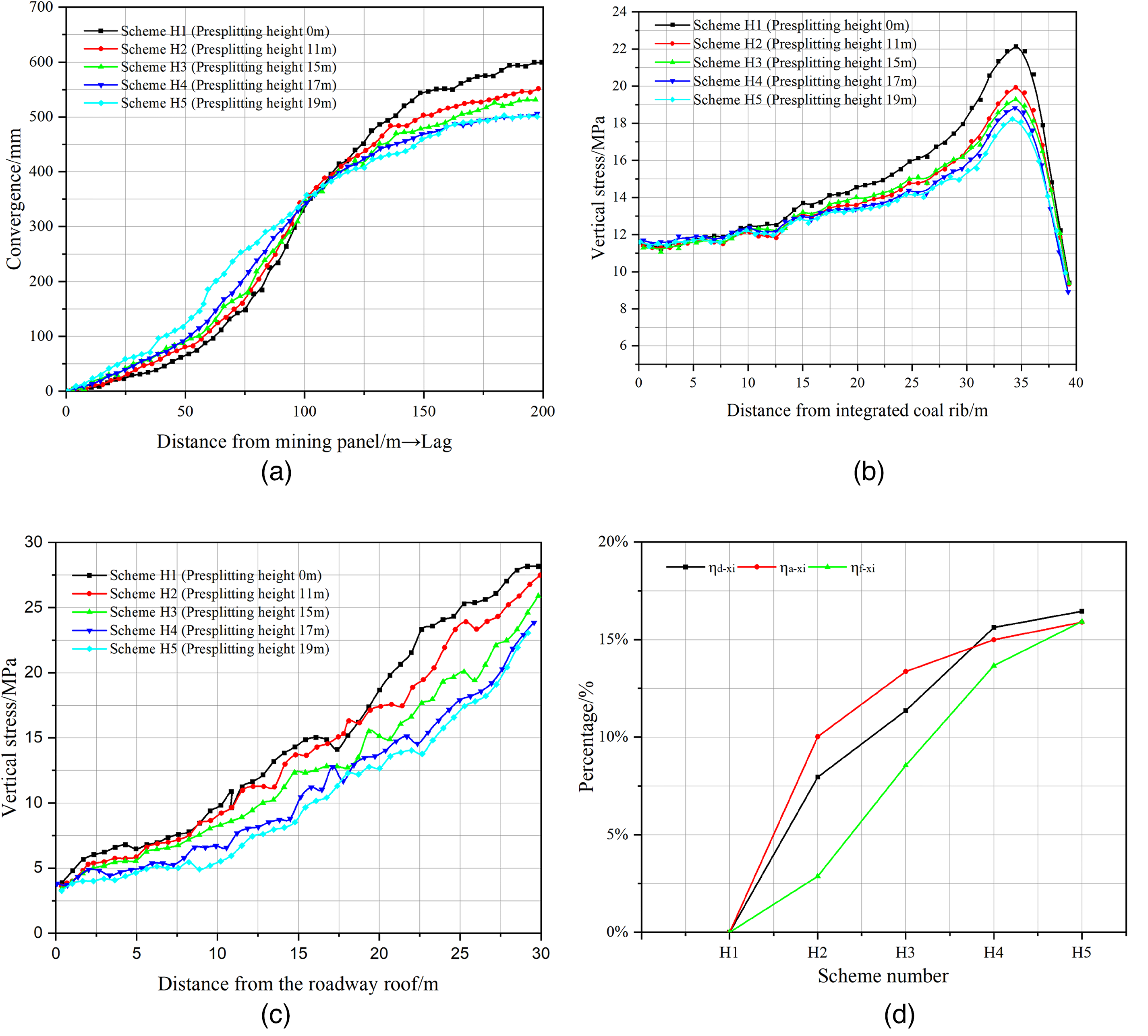
The simulation results analysis of scheme type I with different roof presplitting heights. (a) The convergence of roof and floor of retained entry. (b) The abutment pressure on the integrated coal rib of retained entry. (c) The roof stress of retained entry. (d) The stress and deformation evaluation index.
Results analysis of scheme type II
The presplitting angle is taken as the independent variable, and the scheme numbers A1 to A5 in scheme type II represent 0°, 5°,10°, 15°,and 20° of presplitting angles, respectively. Figure 15 shows the convergence of the roof and floor of retained entry, the abutment pressure on the integrated coal rib, the roof stress of retained entry, and the stress and deformation evaluation index, respectively.
Convergence of roof and floor:
By comparing and analyzing the convergence of roof and floor with different presplitting angles, it can be concluded that: When the presplitting angles are 0, 5, 10, 15, and 20°, the corresponding convergence of roof and floor in the retained entry are 499.45, 460.06, 417.94, 353.62 and 392.75 mm, and the entry deformation control rates (ηd−xi) are 0, 7.89%, 16.32%, 29.20%, and 21.36% respectively, as shown in Figure 15(a) and (d). When the presplitting angle is 15°, the convergence of the roof and floor is the smallest, which is conducive to retaining the entry. Reasonable roof presplitting angle analysis: When the presplitting angle increases from 0 to 15°, the convergence of roof and floor in retained entry reduces gradually. However, when the presplitting angle increases from 15 to 20°, the convergence of the roof and floor in retained entry increases gradually. Increasing the presplitting angle will increase the convergence of the roof and floor after the presplitting angle reaches a certain value. The abutment pressures:
By comparing and analyzing the side abutment pressure with different presplitting angles, it can be concluded that: When presplitting angles are 0, 5, 10, 15, and 20°, the corresponding peak abutment pressures of the integrated coal rib in the retained entry are 18.83, 18.05, 17.81, 17.53 and 19.37 MPa, and peak abutment pressure decrease rates (ηa−xi) are 0, 4.14%, 5.42%, 6.91% and −2.87%, respectively, as shown in Figure 15(b) and (d). When the presplitting angle is 15°, the peak abutment pressure of integrated coal rib in the retained entry is the smallest, which is conducive to retaining entry, and the pressure relief effect is obvious. Reasonable roof presplitting angle analysis: When the presplitting angle increases from 0 to 15°, the peak abutment pressure of integrated coal rib in the retained entry reduces gradually. However, when the roof presplitting angle increase from 15 to 20°, the peak abutment pressure of the integrated coal rib in the retained entry increases gradually. Increasing the presplitting angle will increase the peak abutment pressure of the integrated coal rib after the presplitting angle reaches a certain value. The roof stresses:
By comparing and analyzing the roof stress with different presplitting angles, it can be concluded that: As the presplitting angle increases from 0 to 20°, the average roof stresses of the retained entry are 14.17, 13.71, 11.86, 9.97, and 10.58 MPa, and the stress decreases rates of the roadway roof (ηf−xi) are 0, 6.99%, 16.3%, 29.64%, and 25.34%, respectively, as shown in Figure 15(c) and (d). When the roof presplitting angle is 15°, the average roof stress of the retained entry is the smallest Reasonable roof presplitting angle analysis: When presplitting angles are 0°, 5°, 10°, 15°, and 20°, the corresponding average roof stress in retained entry reduces gradually. However, when the presplitting angle increases from 15 to 20°, the average roof stress in the retained entry increases gradually. A reasonable presplitting angle could effectively cut off the roof stress transfer between the gob and retained entry. Moreover, when the overlying strata collapse, roof presplitting can effectively reduce the frictional resistance, which is conducive to the stability of the retained entry.
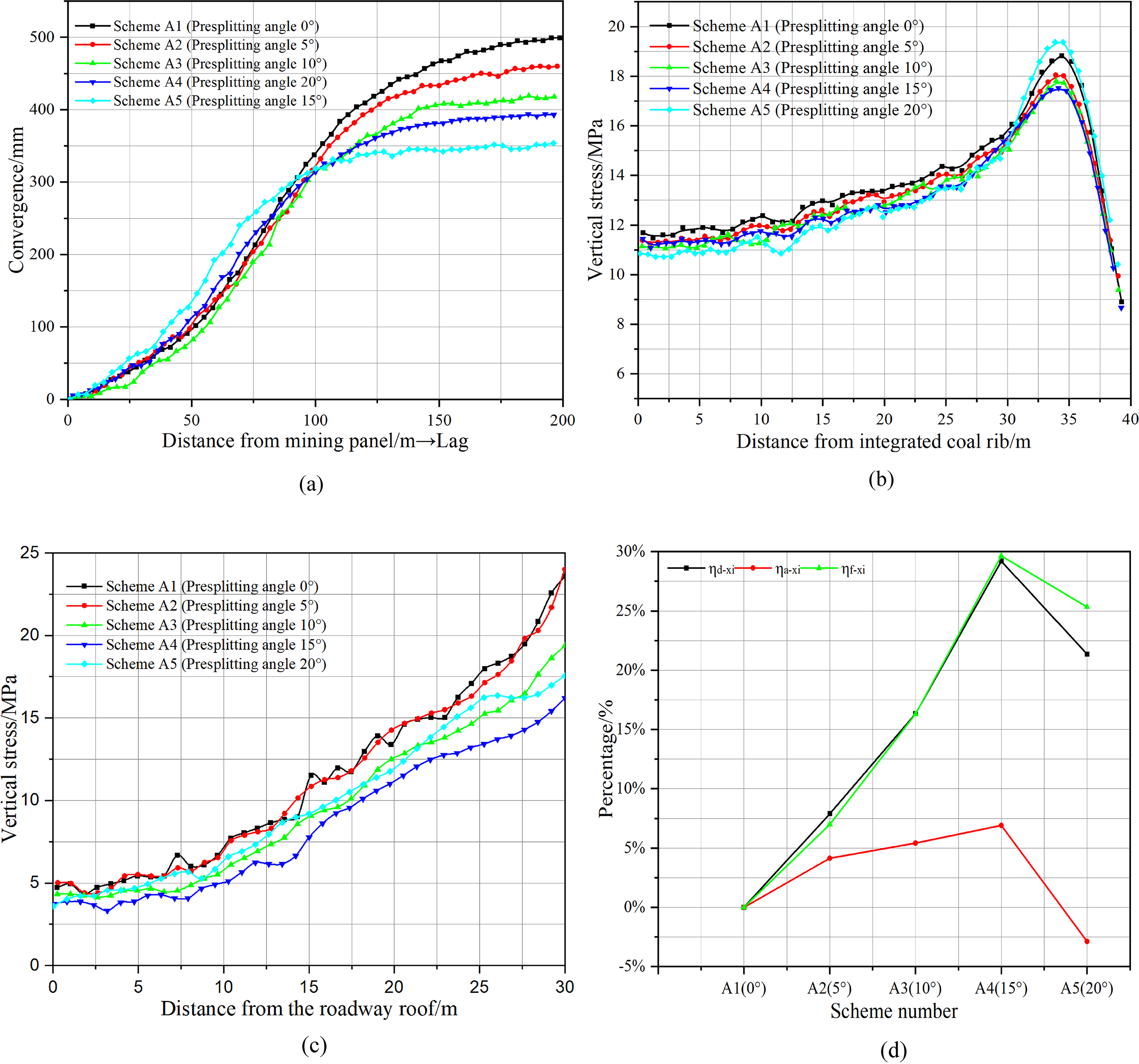
The simulation results analysis of scheme type II with different roof presplitting angles. (a) The convergence of roof and floor of retained entry. (b) The abutment pressure on the integrated coal rib of retained entry. (c) The roof stress of retained entry. (d) The stress and deformation evaluation index.
Summary
By comparing and analyzing the simulation schemes of different presplitting heights. The results show that as the roof presplitting height increases, the abutment pressure of the surrounding rock around the retained entry gradually decreases. However, when the presplitting height exceeds 17 m, the magnitude of abutment pressure variation is small.
By comparing and analyzing the simulation schemes of different presplitting angles. The results show that as the presplitting angle increases, the abutment pressure of the integrated coal rib in retained entry decreases first and then increases. A reasonable presplitting angle could effectively cut off the roof stress transfer between the gob and retained entry (Kainthola et al., 2021). Moreover, the roof presplitting can effectively reduce the frictional resistance, which is conducive to the stability of the retained entry.
Based on the above theoretical analysis and numerical comparison test, it can be concluded that under the geological conditions of 150202 LTCC working face in the Shenlei Coal Mine, the reasonable roof presplitting height is 17 m, and the presplitting angle is 15°.
Field application
To verify the validity of the above mechanism of roof presplitting and numerical simulation tests, two sets of field comparison experiments with the presplitting height and presplitting angle as variables and the ground response of retained entry is analyzed in the field engineering experiments.
Schemes of presplitting height design
Roof presplitting can not only cut off the roof stress transfer between the gob and the roadway but also ensure the roof strata above the gob easier to collapse and take advantage of the expansion characteristics of the collapse gangue to fill the gob (Wang et al., 2021; Wang et al., 2022). Therefore, according to the balanced mining theory, considering the convergence of roof and floor, the theoretical roof presplitting height is as follows (Gao et al., 2019b):
where Hp is the roof presplitting height, m; M is the thickness of coal seam, m; ΔH1 is the subsidence of the roadway roof, m; ΔH2 is the floor heave of the roadway, m; and K is the average bulk factor of the overlying strata.
The average bulk factor of the rock strata above the 150202 LTCC panel of Shenlei Coal Mine is 1.4. Considering the convergence of the roof and floor of the 150202 headgate, the theoretical roof presplitting height is about 17 m. To study the effects of presplitting height on the ground response of retained entries, three kinds of presplitting schemes are designed (schemes Ι, II, and III), as shown in Figure 16(a), (b) and (c). The experimental length of each scheme is 200 m. The roof presplitting technique adopts the multihole co-blasting method, and the blasting hole diameter is 50 mm. The BECD is installed in the blasting hole. In scheme Ι, the roof presplitting angle is 15°, the presplitting height is 15 m, 9 BECDs are installed in each blast hole, and the installation method of emulsion explosives is 4 + 3 + 3 + 3 + 1 + 3 + 3 + 2 + 2(number of emulsion explosive rolls), and the length of the water stem of the blasting hole is 2.5 m; In scheme II, the roof presplitting angle is 15°, the presplitting height is 17 m, 10 BECDs are installed in each blast hole, the installation method of emulsion explosives is 4 + 3 + 3 + 3 + 3 + 2 + 3 + 3 + 2 + 2, and the length of the water stem of the blasting hole is 2.5 m; In scheme III, the roof presplitting angle is 15°, the presplitting height is 19 m, 11 BECDs are installed in each blast hole, the installation method of emulsion explosives is 3 + 4 + 3 + 3 + 3 + 3 + 2 + 3 + 3 + 2 + 2, and the length of the water stem of the blasting hole is 2.5 m, as shown in Table 5.
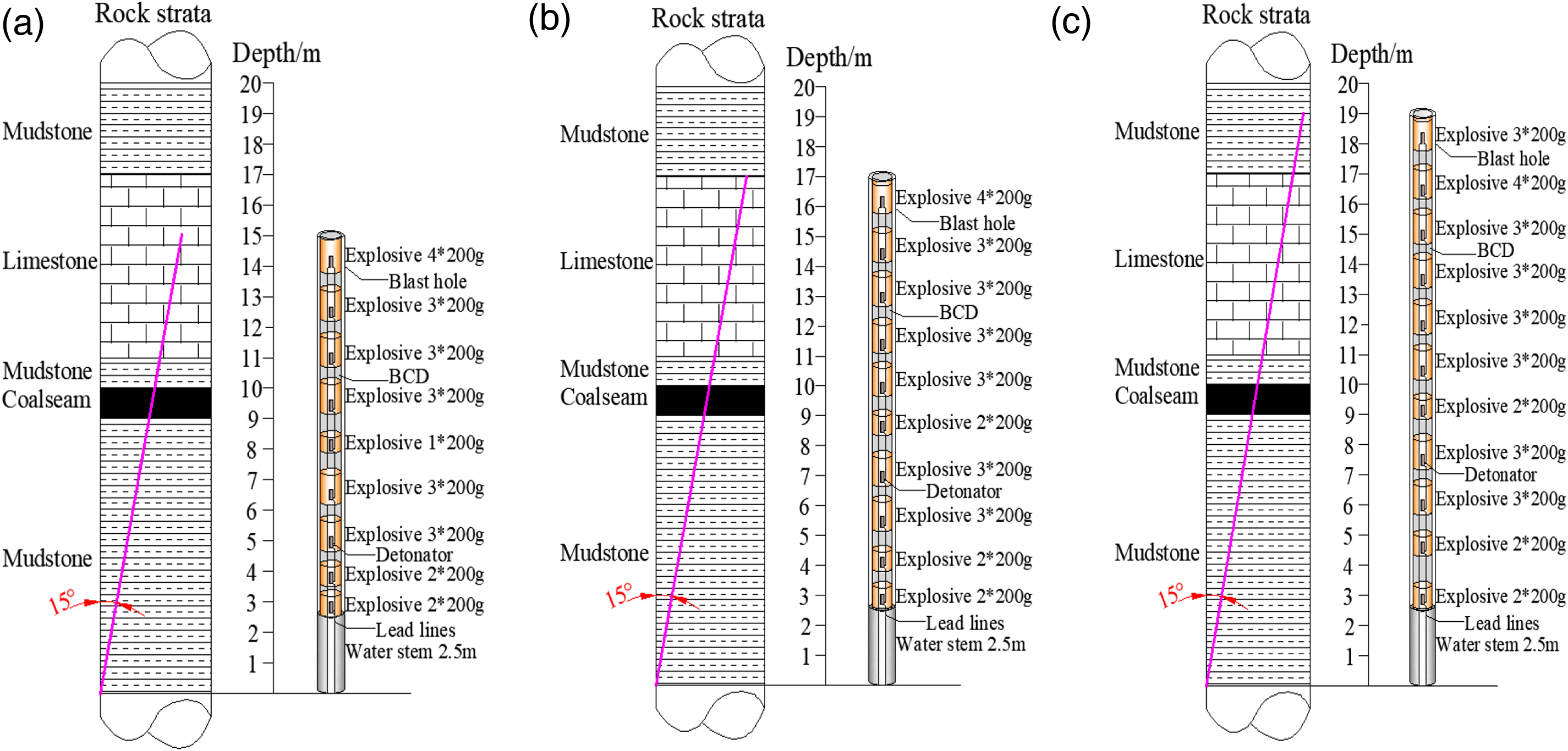
Presplitting heights design in the field application: (a) scheme Ι, (b) scheme II, and (c) schemeIII.
Schemes of the presplitting height in the field application.
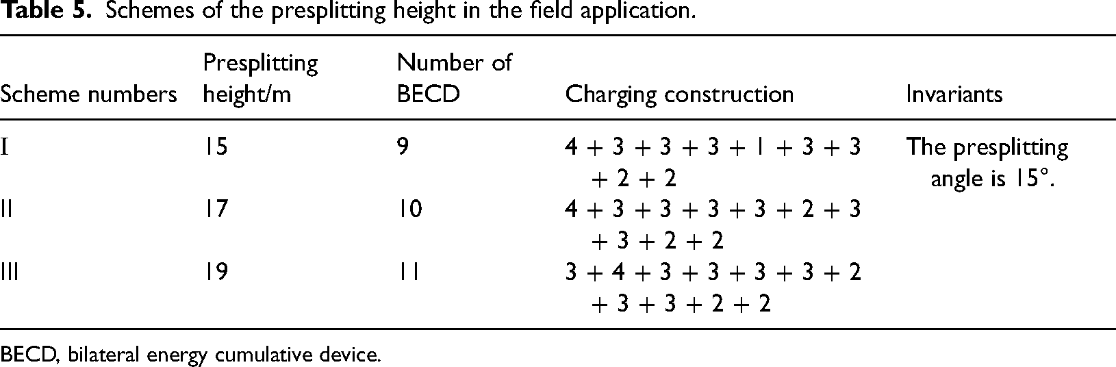
BECD, bilateral energy cumulative device.
Schemes of presplitting angle design
To study the effect of the presplitting angle on the ground response of retained entries, three kinds of presplitting schemes are designed (schemes IV, V, and VI), as shown in Figure 17(a), (b) and (c). In scheme IV, the roof presplitting angle is 0°, the presplitting height is 17 m, 10 BECDs are installed in each blast hole, the installation method of emulsion explosives is 4 + 3 + 3 + 3 + 3 + 2 + 3 + 3 + 2 + 2, and the length of the water stem of the blasting hole is 2.5 m. In scheme V, the roof presplitting angle is 10°, the presplitting height is 17 m, 10 BECDs are installed in each blast hole, the installation method of emulsion explosives is 4 + 3 + 3 + 3 + 3 + 2 + 3 + 3 + 2 + 2, and the length of the water stem of the blasting hole is 2.5 m; In scheme VI, the roof presplitting angle is 20°, the presplitting height is 17 m, 10 BECDs are installed in each blast hole, the installation method of emulsion explosives is 4 + 3 + 3 + 3 + 3 + 2 + 3 + 3 + 2 + 2, and the length of the water stem of the blasting hole is 2.5 m, as shown in Figure 16 (Table 6).
Presplitting angles design in the field application: (a) scheme IV, (b) scheme V, and (c) scheme VI.
Schemes of the presplitting angle in the field application.
BECD, bilateral energy cumulative device.
Roadway monitor scheme
The cross-section of the experimental 150202 headgate is rectangular with a width and height of 5.2 m and 3.2 m, respectively. It adopts the combined support technology including anchor bolts, anchor cables, and steel mesh. To clarify the pressure relief effect of roof presplitting, we monitor the surface displacement of the retained entry during the mining process of the working face after roof presplitting. Five monitoring stations are installed in the 150202 headgate to monitor the roadway convergence cure of each scheme, as shown in Figure 18 (where AB is the convergence between roof and floor and CD is the convergence of two ribs).
Plan view of the roadway deformation monitor scheme.
Analysis of field engineering test
Influence of presplitting heights on the ground response of entries
During the roadway retention process, the deformation of the roadway is monitored in the five field experimental sections, respectively. The convergence of the roof and floor with different presplitting heights are shown in Figure 19. The monitoring results show that, within the range of the advanced temporary support of the panel, the deformation of the roadway increases gradually with the advancement of the working face. When the roof presplitting height is 15 m, the roadway deformation rate gradually increases within 0–110 m behind the panel. When the lagging length from the working face reaches 200 m, the convergence between the roof and floor is stable at 500 mm. When the roof presplitting height increases to 17 m, the speed of roof collapse increases, and the roadway deformation rate increases gradually within 0–60 m behind the panel. At the position of 160 m behind the panel, the convergence of the roof and floor tends to be stable at 400 mm which is a 20% reduction compared with the presplitting height of 15 m. When roof presplitting height increases to 19 m, the final deformation of the retained entry does not change much. The deformation of the roof stabilized at about 400 mm. The stabilized distance has decreased to 150 m, which is a 6% reduction compared with the presplitting height of 17 m.
The convergence of roof and floor with different presplitting heights.
The measured results of the deformation law of the roadway surrounding rock in the field experiments are similar to the numerical simulation. The increasing of the roof presplitting height is beneficial to reduce the deformation of the retained entry within a certain range of presplitting height. This is attributed to that the roof presplitting can cut off the roof stress transfer and fill the gob using the expansion characters of gob materials.Therefore, the roadway is located in the pressure relief area. However, the increasing of the presplitting height does not have a significant effect on pressure relief after the collapse gangue full fill the gob area. Therefore, the lithology and bulk factor of the overlying strata and the collapse and stabilization process of the overlying strata should be comprehensively considered in the design of the roof presplitting height.
Influence of presplitting angle on the ground response of entries
The convergence of the roof and floor with different presplitting angles are shown in Figure 20. The monitoring results of the convergence of roof and floor show that, within the range of the advanced temporary support of the panel, the deformation of the roadway increases gradually with the advancement of the working face. When the roof presplitting angle is 10°, the roadway deformation rate gradually increases within 0–70 m behind the panel. When the lagging length from the working face reaches 190 m, the convergence between the roof and floor is stable at 550 mm. When the presplitting angle increases to 15°, the speed of overlying strata collapse increases, and the roadway deformation rate increases gradually within 0–60 m behind the panel. At the position of 160 m behind the panel, the convergence of the roof and floor tends to be stable at 400 mm which is a 27.27% reduction compared with the presplitting angle of 10°. When the roof presplitting angle increases to 20°, the deformation of the retained entry starts to increase, and finally stabilizes at 450 mm, which is a 12.5% increase compared with the presplitting angle of 15°.
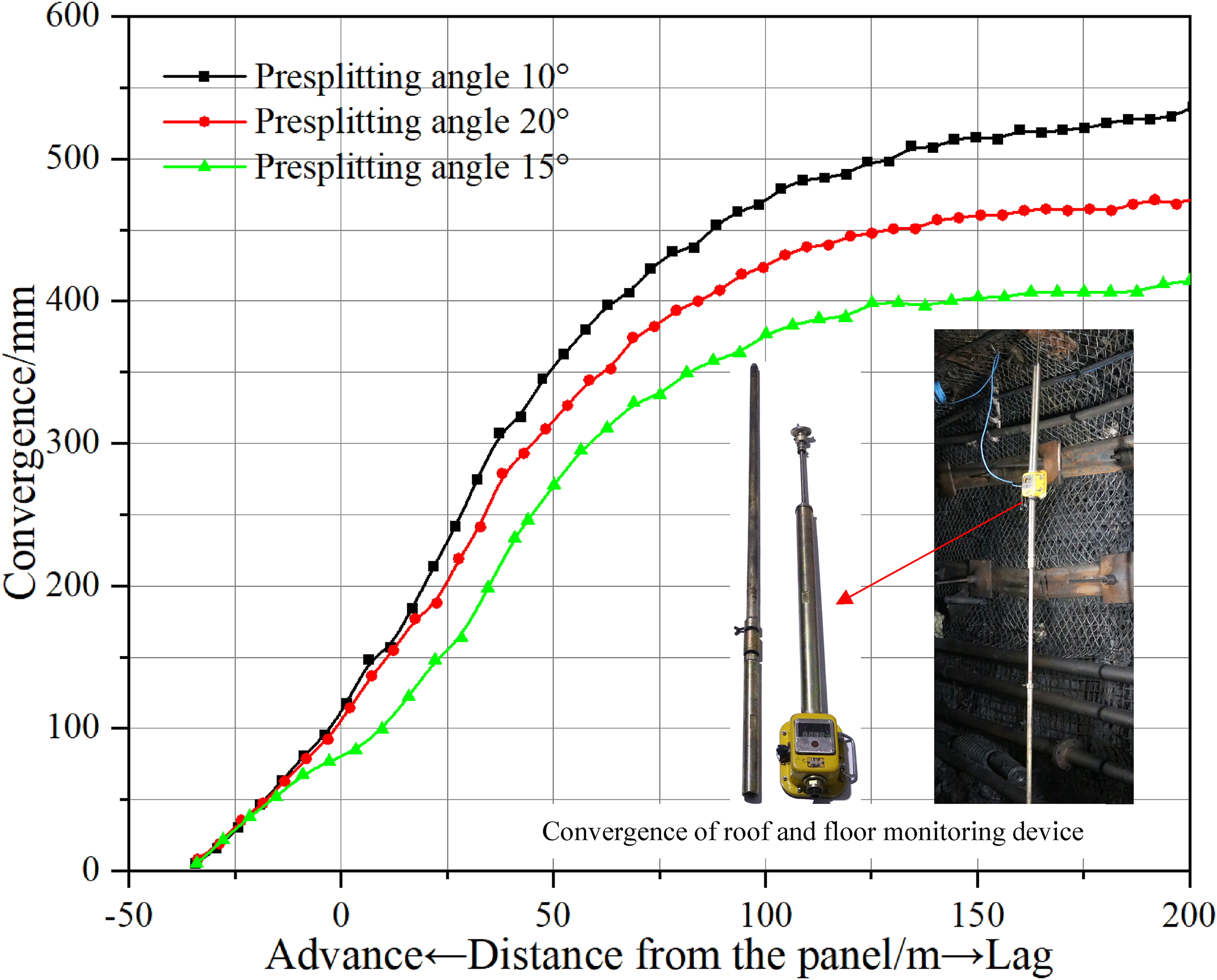
The convergence of roof and floor with different presplitting angles.
The measured results of the deformation law of the roadway surrounding rock in the field experiments are similar to the numerical simulation. Increasing the roof presplitting angle is beneficial to reduce the deformation of the retained entry within a certain range of presplitting angles. This is because the roof presplitting line with a certain deflection angle in the gob, which is beneficial to weaken the friction resistance on the cutting cantilever beam structure when the gangue collapses. However, an excessively large roof presplitting angle is not conducive to the stability of the roadway. Therefore, the lithology of the overlying strata and the conditions of drill construction in the roadway should be comprehensively considered in the design of the roof presplitting angle.
Effect of final presplitting scheme
According to the above research results, we can conclude that the reasonable roof presplitting height of the 150202 LTCC panel is 17 m, the presplitting angle is 15°, the blasting hole spacing is 500 mm, the installation method of emulsion explosives is 4 + 3 + 3 + 3 + 3 + 2 + 3 + 3 + 2 + 2, and the length of the water stem of the blasting hole is 2.5 m. After roof presplitting, a fiber borehole observation rig (instrument model ZKXG30) is used to detect the expansion of cracks in the blast holes. The effect of roof presplitting and automatically retained entry are shown in Figures 21 and 22, respectively. Figure 21(a) and (b) show that the cracks propagate in the preset direction, which verifies the reliability of the BCTE technique. Figure 21(c) shows that the overlying strata above the gob collapse along the presplitting line, and finally compact and stabilize to form a gangue rib of retained entry. Figure 22 shows the final effect of the automatically retained entry after roof presplitting.
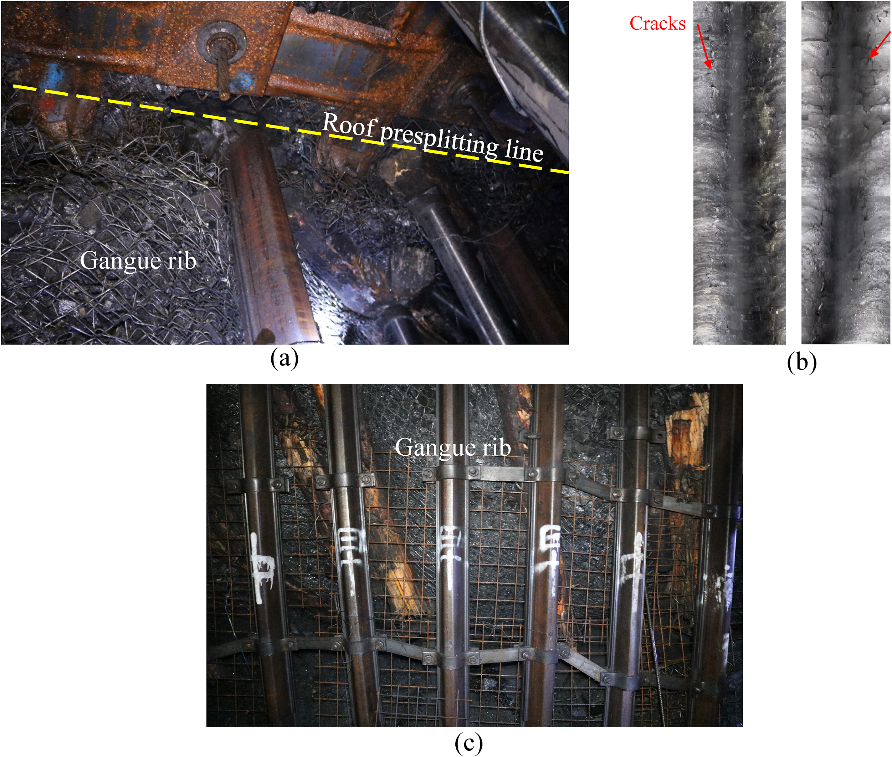
The effect of roof presplitting: (a) overlying strata collapse after roof presplitting, (b) cracks penetration of blasting hole, and (c) the gangue rib of retained entry behind the working face.
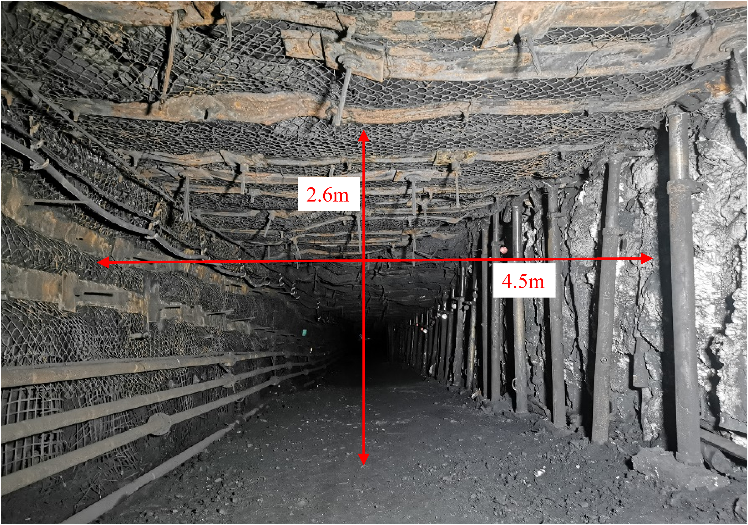
The effect of the automatically retained entry with roof presplitting height and angle of 17 m and 15°.
Discussion and conclusions
When Shenlei Coal Mine adopts the LTCC mining method, the surrounding rock of the newly excavated entries adjacent to the LTCC panel will experience large deformation, which is not only prone to various roof accidents but also causes the mine pit excavation replace seriously out of balance. Therefore, to control the large deformation of the excavated entry adjacent to the LTCC panels, the nonpillar coal mining technology with entry automatically retained by roof presplitting has been applied in Shenlei Coal Mine.
A mechanical model of overlying strata after roof presplitting is established to study the mechanism of roof presplitting. By analyzing the relationship between the tensile stress on the unpenetrated surface of the main roof and the presplitting parameters, it can be concluded that: When the presplitting angle remains constant, the tensile stress at the unpenetrated surface is approximately exponentially distributed with the presplitting height. When the presplitting height remains constant, the variation curve of tensile stress at the unpenetrated surface with the presplitting angle is parabolic.
The numerical simulation results show that increasing the presplitting height and presplitting angle within a certain range could reduce the deformation of retained entry. But increasing the presplitting height does not significantly affect the ground response of retained entry after the roof presplitting height reaches a certain value. Increasing the presplitting angle will continue to increase the deformation of the retained entry after the roof presplitting angle reaches a certain value.
Finally, it is concluded that the reasonable presplitting height and angle are 17 m and 15° in the LTCC panel of Shenlei Coal Mine, respectively. The field application shows that reasonable roof presplitting parameters could achieve satisfactory effects at pressure relief and retained entry in the LTCC panel.
Footnotes
Acknowledgements
The authors are very grateful to the editors and reviewers for their kind and invaluable comments.
Data availability statement
All data are included in the manuscript as tables and figures and have been uploaded as part of the electronic supplementary material.
Declaration of conflicting interests
The author(s) declared no potential conflicts of interest with respect to the research, authorship, and/or publication of this article.
Funding
The author(s) disclosed receipt of the following financial support for the research, authorship, and/or publication of this article: This work was supported by the Guizhou Province Science and Technology Planning Project, State Key Laboratory for GeoMechanics and Deep Underground Engineering, China University of Mining & Technology/China University of Mining & Technology, Beijing, National Natural Science Foundation of China Youth Science Foundation Project, and China Scholarship Council (grant numbers [2020] 2Y030, [2020]2Y019, [2020]3007, [2020]3008, [2022] 011, SKLGDUEK2132, 52104139, and 202006430058).