
Abstract
A thick-hard roof implies a large hanging-roof and high-frequency dynamic strata behaviour during mining, which may jeopardise personnel safety and equipment. To alleviate these hazards, deep-hole pre-splitting blasting is employed to control periodic fractures in thick-hard roof seams in Datong mining area. Based on loading and instability characteristics, a mechanical model of thick-hard roof periodic collapse is established to investigate the relationships and optimal parameters among the collapse interval, fracturing angle and support working resistance. LS-DYNA was employed to analyse the fracture evolution to determine the optimal charge parameters. The minimum weakening width and average fragmentation of the pre-split roof are obtained. Universal distinct element code simulations were used to determine the thick-hard roof collapse morphology and strata behaviour to confirm the optimal pre-splitting parameters. The deep-hole pre-splitting blasting on-site implementation reduces thick-hard roof collapse intervals, and the supports loading is verified to be safe with sufficient allowance, which show a good control effect on thick-hard roof seams.
Keywords
Introduction
The presence of a thick-hard roof (THR) in coal mines often causes excessive stress concentration and dynamic strata behaviour. Theoretical analyses and in-situ seismic monitoring results have indicated that most sources of rockbursts are located in strata with high strength and integrity (such as thick sandstone immediately overlying the seam), and thus THR is a common origin of rockbursts.
In the Datong mining area, the main mining coal seams belong to Jurassic and Carboniferous formations, which include at least one THR in the near-field that generally falls within the range of the caving zone. Owing to its large thickness and good integrity, the roof weighting of the longwall face is extremely pronounced (Xia et al., 2017; Yang et al., 2017b). A large area of the suspended roof appears before fracturing, and its length can exceed 20 m (Jiang et al., 2019; Zuo et al., 2019). Because the deformed THR accumulates a large amount of elastic energy, its release during a sudden rupture may break the supports and induce strong dynamic shocks, which poses a severe threat to production safety (Unver and Yasitli, 2006; Yang et al., 2014).
To alleviate the strong pressure behaviour, the fracturing structure of the THR should be analysed, and corresponding positive control measures should be employed for pre-splitting to control THR migration in advance (Ghasemi et al., 2017; Yu et al., 2015). At present, the main control technologies are deep-hole pre-splitting blasting (DPB) and hydraulic fracturing (Barras et al., 2012; Liu et al., 2017; Raftoyiannis et al., 2007; Ye et al., 2017). Hydraulic fracturing has been used to cut the hard roof to relieve the pressure, thus obtaining a reasonable length of 8.8 m for roof fracturing of the large upper goaf-side coal pillars. After fracturing, the local stress concentration in the coal pillars was reduced, which controlled the deformation of the surrounding rock of the roadway (Liu et al., 2020). Directional hydraulic fracturing is characterised by cutting a groove in the borehole and then injecting high-pressure water to break the rock. The vertical compressive stress can be changed to tensile stress after liquid injection, which easily ruptures the roof (He et al., 2012). However, DPB is widely used because of its simplicity, significant effect, and strong adaptability (Xia et al., 2018). Numerical and physical simulations have been performed to analyse the collapsed structure and determine the relationship between the supports and the surrounding rock. By adjusting the pre-splitting simulation parameters, the reasonable control length and blasting parameters were optimised to achieve the best technical results (Wang et al., 2013). In a longwall top-coal caving working face, the displacement and breaking level of a double-layer THR were examined. Upon adopting deep-hole blasting, the panel excavation could be ensured, showing low-frequency instability (Ning et al., 2017). By investigating the characteristics of micro-seismic events and the movement patterns of THR, it was concluded that the key to controlling the strata behaviour lies in determining the failure mode, and the implementation of DPB could prevent the occurrence of impact accidents (Zhang et al., 2019, 2020). The variation in the support resistance was obtained for different layer combinations of key strata caving. Based on the fracturing-controlled THR, the appropriate support type was selected (Liu et al., 2015; Yu et al., 2018). Directional pre-splitting of the THR was carried out by adding guiding holes, and the fracturing mechanism was analysed. A favourable technical result was obtained for the site application (Chen et al., 2018b). Equal deep and ladder-like distributed hole blasting processes were simulated to analyse and compare the stress evolution using LS-DYNA to determine which scheme was more effective. Field testing results showed that ladder-like distributed blasting significantly reduced the initial pressurised distance and weighting intensity of the roof (Zuo et al., 2016). The deep-shallow combination of DPB increased the probability of the blasting fracture density and multi-directional development and resulted in more even blasting fragmentation (Zhao, 2021).
However, most studies have focused on the initial fracture of the THR and have neglected the synergistic control of periodic pre-splitting parameters and support resistance. Traditional blasting usually involves the excavation of empty holes instead of the pre-splitting zone in the simulation, which somewhat influences the THR collapse behaviour. Therefore, based on the THR characteristics of the Xinzhouyao Mine in the Datong mining area (China), the collapse morphology was analysed, and the relationship between fracturing-articulated strata and support resistance was obtained to derive the optimal pre-splitting parameters. Based on the fracture distribution assessed via LS-DYNA in the middle weakening zone, a discrete element analysis of THR caving was carried out to validate the controlling effect of DPB on THR. Finally, this study presents a roof caving design that can ensure safer mining in THR seams.
Loading and collapse characteristics of THR
Engineering geology conditions
The 309 panel in Xinzhouyao Mine has a coal thickness ranging from 5.2 to 8.8 m (with an average thickness of 7.2 m and dip angle of 3°). The lithological characteristics are shown in Figure 1(a). The immediate roof is composed of 1.8 m of mudstone and 2.7 m of fine sandstone. The main roof, with an average thickness of 13.7 m, consists of medium sandstone. The low degree of primary fracture development and high integrity of the rock core are illustrated in Figure 1(b) and (c). Therefore, the 13.7 m of medium sandstone is a typical THR.
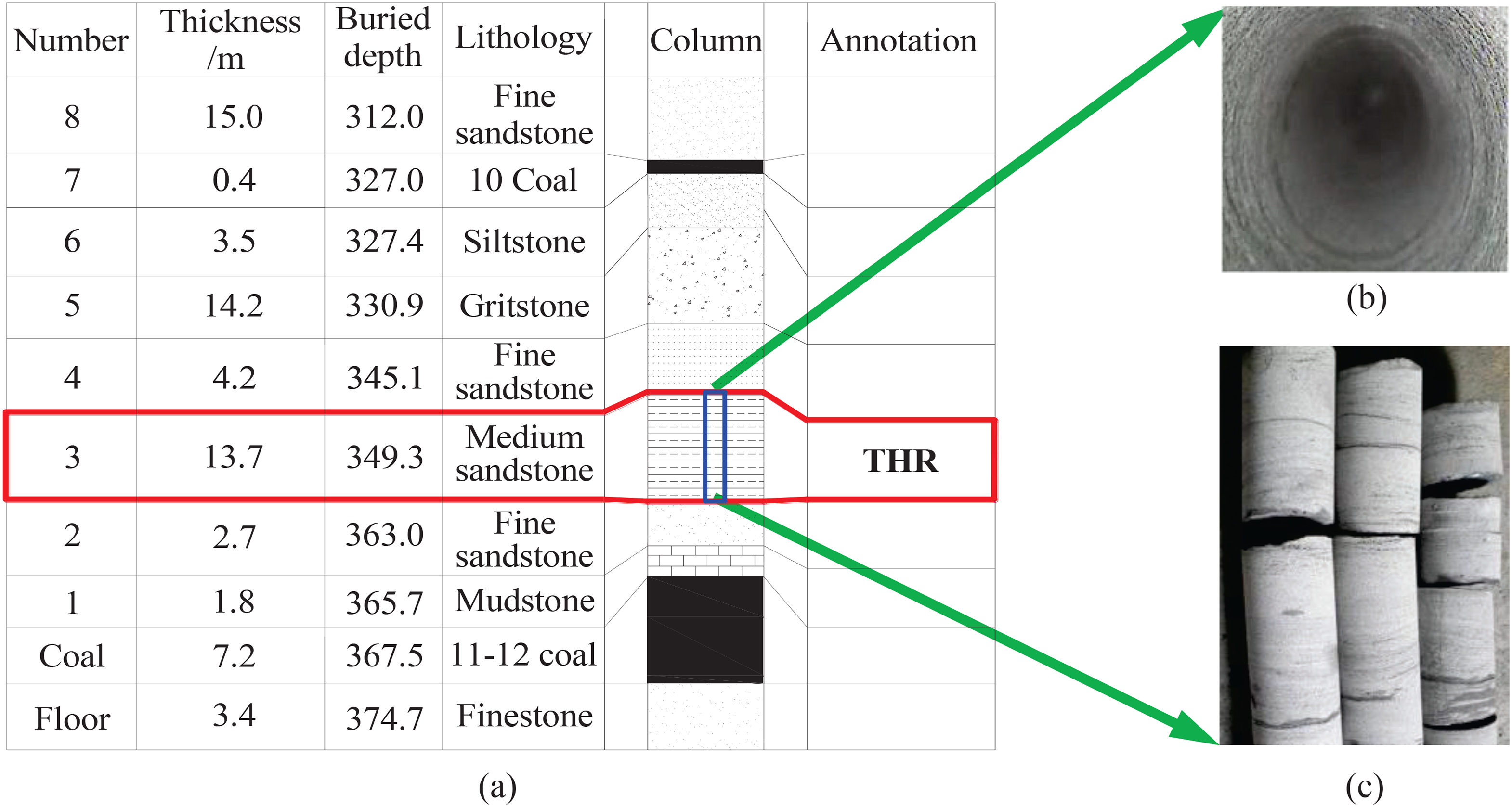
Strata distribution and thick-hard roof (THR) characteristics: (a) stratigraphic column; (b) fracture development of THR drilling and (c) integrity of medium sandstone cores.
As the working face advances, the THR will hang with a large-sized collapse, which can induce strong pressure behaviour, including severe deformation of the roadsides, pillar breakage, spalling of a large area of the coal wall and crushing of the supports. Therefore, the THR is pre-split to weaken the rock between blasting holes, thus reducing the collapse intervals and improving the pressure behaviour.
Characteristics of THR fracturing
After the initial collapse, as the working face advances, the THR forms a combined cantilever structure with a free side in the goaf (Figure 2). Considering the bearing characteristics for different lithologies and thicknesses, a multi-level inverted trapezoid cantilever beam with uniformly distributed loading is proposed and employed to analyse the THR fracture and instability (Liu et al., 2015).
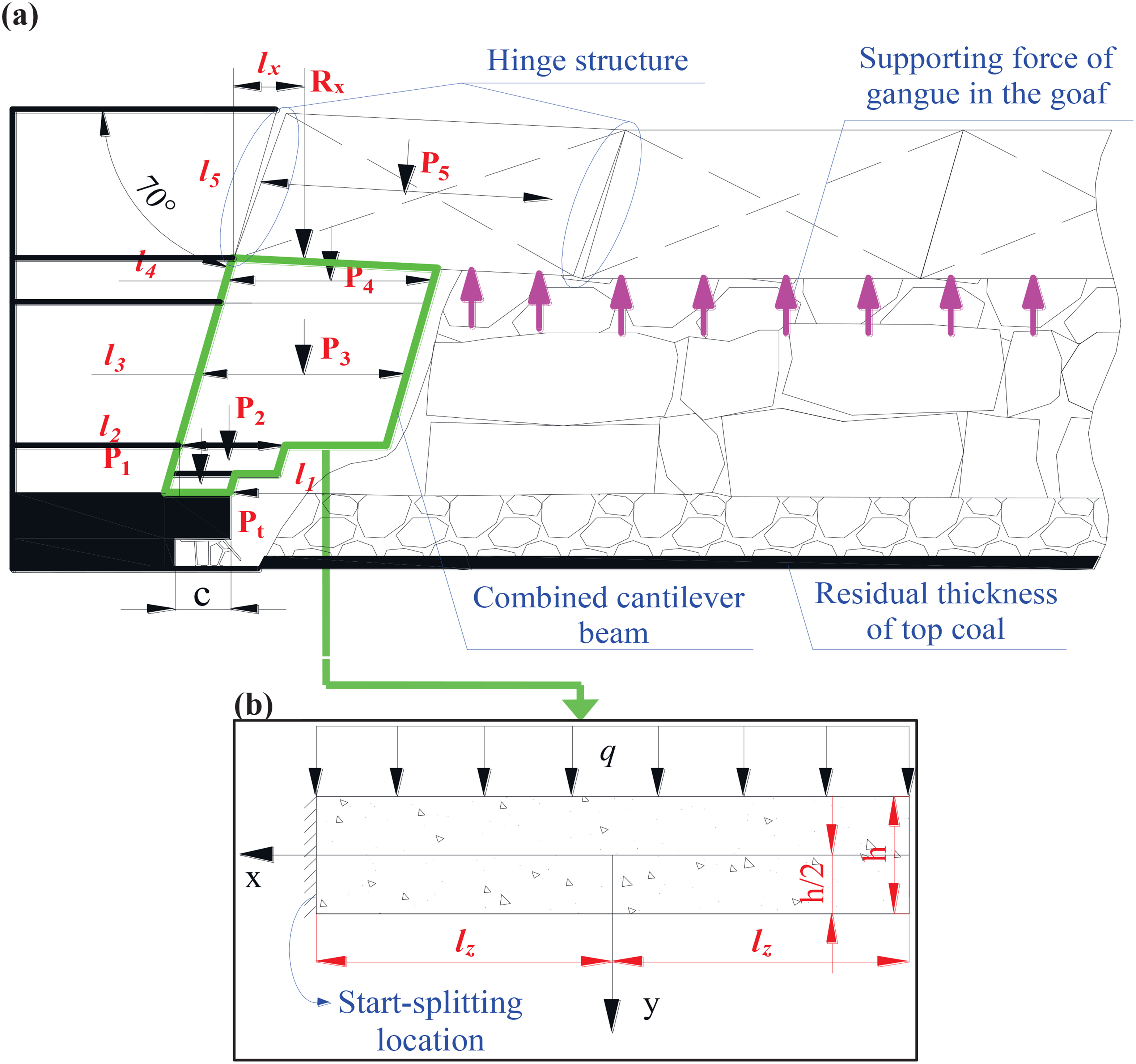
Mechanical model of thick-hard roof (THR) fracturing and instability: (a) combined cantilever beam articulated structure and (b) mechanical model of the cantilever beam with one fixed end.
Considering the loading and instability characteristics, the support loading is subdivided into three parts: (i) the weight loading, including the top coal (depending on the control distance) and the combined cantilever beam; (ii) loading induced by the fracturing angle of the caving zone; and (iii) the additional loading of the upper articulated strata. Therefore, taking the hydraulic support as the research unit, the critical stability condition is obtained in the following form:
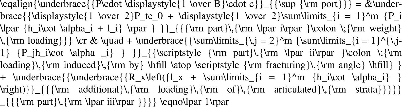
The spatial dimensions of the combined cantilever beam should be determined by considering the parts of the strata loading. First, it is necessary to determine the horizon of the cantilever beam and the articulated strata. According to the gradual expansion of the rock strata, considering the residual top coal and the caving rock filling the goaf, the total caving height is taken as the thickness of the cantilever beam as follows:
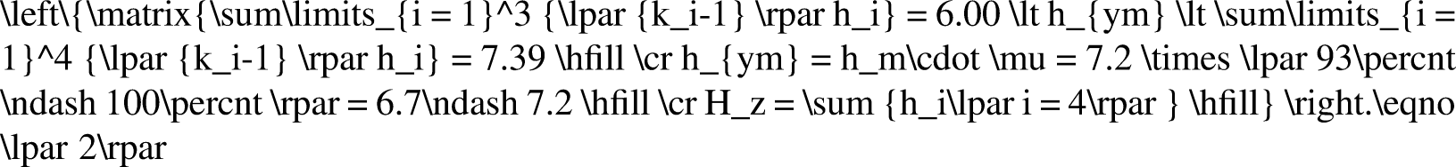
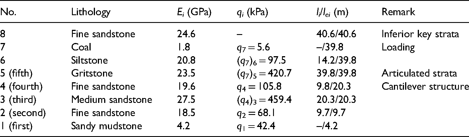
Therefore, Hz can be determined as a sum of 1.8 m of mudstone, 2.7 m of fine sandstone, 13.7 m of medium sandstone and 4.2 m of fine sandstone. The fracture-articulated structure is formed in 14.2 m of gritstone. Then, based on the fracturing position of the strata, it is necessary to derive the periodic fracturing intervals of the loading strata and the action characteristics of the additional loading (i.e. the dimensions of the cantilever beam and the applied loading of the articulated stratum).
Strata layer caving intervals
Before THR fracturing, the strata present a cantilever structure with uniformly distributed loading. Based on the action of the adjacent strata, the layer loading, qi, can be determined (Huang et al., 1999):
Therefore, the loading on each layer can be calculated.
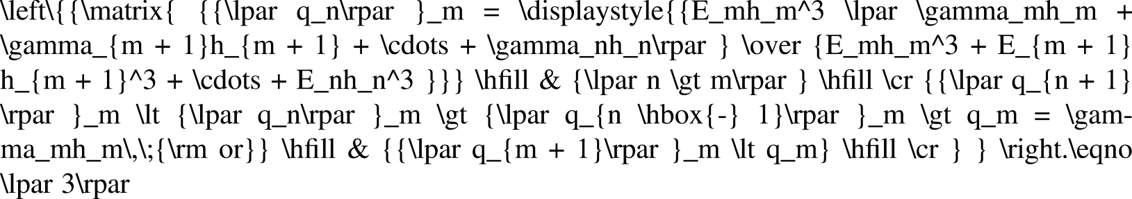
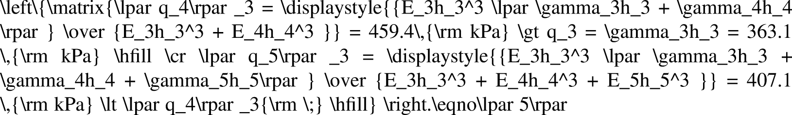
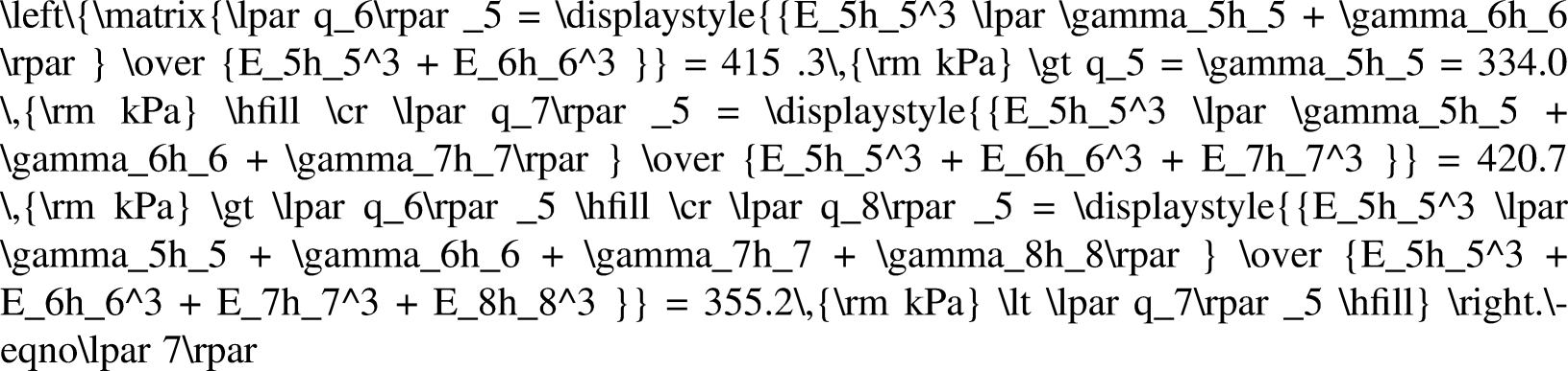
The loading of the first layer composed of 1.8 m of mudstone can be obtained as follows: Therefore, the loading of the first layer is determined at q1, that is, 42.4 kPa. Because the thickness and elastic modulus of the third layer (13.7 m of medium sandstone) are larger than those of the second layer (2.7 m of fine sandstone), it is the loading layer (THR). Therefore, the loading of the second layer is determined at q2 = γ2h2, that is, 68.1 kPa. The loading of the third layer composed of 13.7 m of medium sandstone can be obtained as follows: As discussed above, the loading of the third layer is determined at (q4)3, that is, 459.4 kPa. The loading of the fourth layer composed of 4.2 m of fine sandstone can be obtained as follows: Through comparative analysis, the loading of the fourth layer is determined at q4, that is, 105.8 kPa. The loading of the fifth layer composed of 14.2 m of gritstone can be obtained as follows:
Thus, the loading of the fifth layer is determined at (q7)5, that is, 420.7 kPa.


Combined with the maximum tensile stress at the clamped end (Xu, 2013), li can be expressed as follows:

Therefore, parameters including (qn) m , li, and the minimum cantilever length of each layer (lei) are listed in Table 1.
Loading and fracturing intervals of rock strata.
Additional loading of the articulated strata
The articulated strata are in mechanical equilibrium under the synergistic action of the dead weight, supporting force from the upper cantilever beam, uniform loading and extrusion force from the adjacent block. The mechanical model is thus obtained as shown in Figure 3.
Mechanical model of additional loading of the articulated stratum.
According to the mechanical model, the stability condition of the fracture-articulated block is:
Combining the characteristics of the contacting crushed surface, Rx can be obtained as follows:
Additional loading response for different periodic pre-splitting intervals and roof subsidence values.
Figure 4 shows that the additional loading is proportional to THR caving intervals and decreases slightly with the increase in Δh. Therefore, for a specific interval, the loading reaches the maximum at Δh = 0, corresponding to the most dangerous situation. Thus, the support-bearing loading is at least 26.6 MN, and the existing support cannot meet the needs of safety production. Consequently, DPB is proposed for pre-splitting of the THR and controlling migration; the controlling factors are the periodic pre-splitting intervals and angles. The mechanical model after pre-splitting is illustrated in Figure 5.
Fracturing model of the thick-hard roof (THR) after periodic pre-splitting.
After pre-splitting, lx decreases with the shortening of the cantilever length, lei (Chen and Liu, 2018a; Yu et al., 2015). Considering that le3 is larger than le2 (2.7 m of fine sandstone), le2 = 9.7 m is regarded as the boundary of the continuous curve. Therefore, combined with equation (1) under Δh = 0 and lx = 0, the subsection stability conditions of the supports can be obtained (equation (11)), and the variation curve between βi and lei is shown in Figure 6.
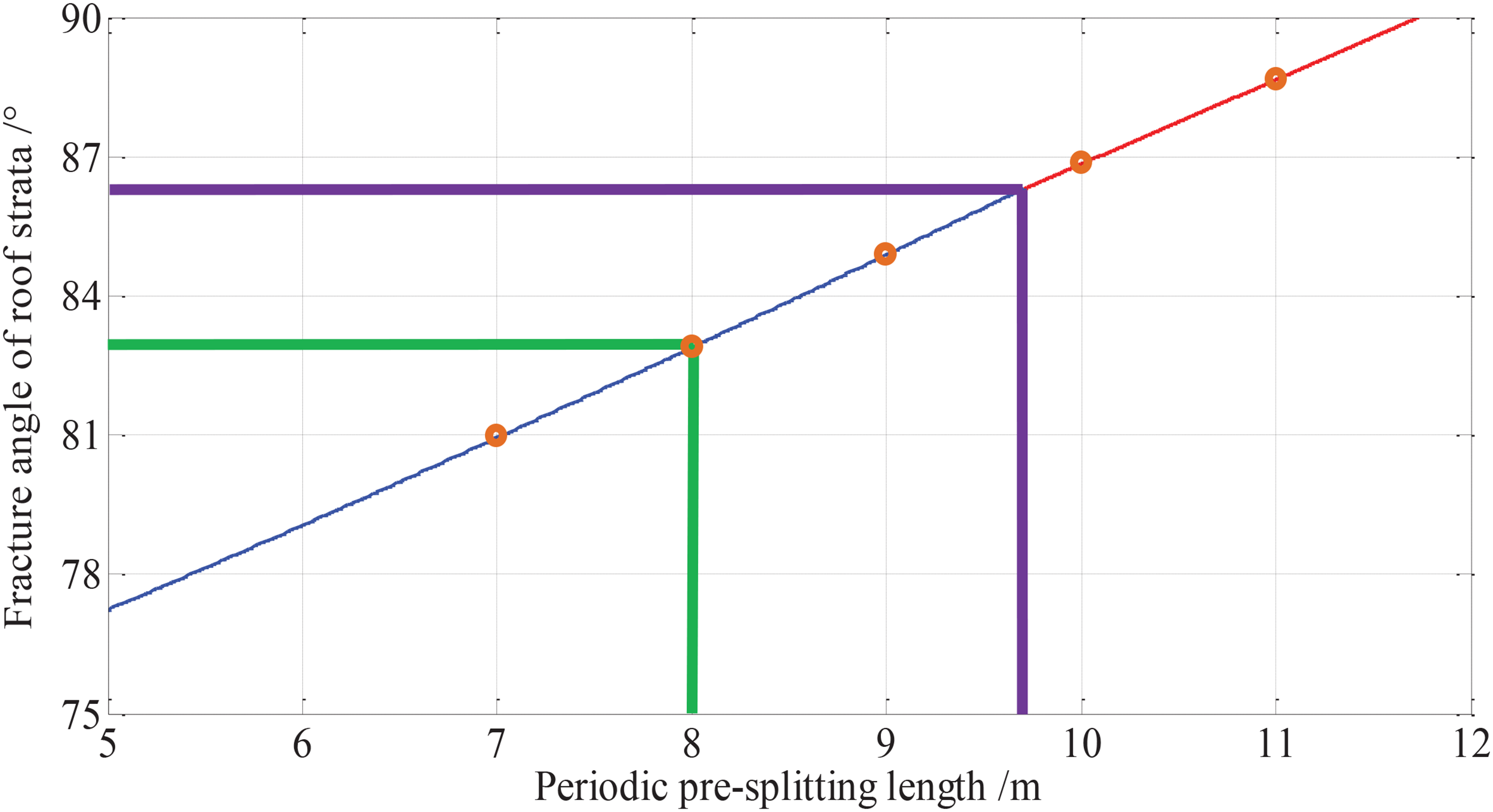
Relationship between the critical pre-splitting interval and fracture angle.
Figure 6 shows that the periodic pre-splitting interval exhibits a nearly linear relationship with the fracture angle. When the fracture angle approaches 0°, the THR tends to exhibit full-thickness shear falling along the pre-splitting line, resulting in the impact of dynamic loading and crushing of the supports. However, when the pre-splitting rotation angle is greater, the drilling workload will increase exponentially, which is irrational from an economic perspective. Therefore, considering the support stability and the relationship in Figure 6, the optimised pre-splitting interval is 8.0 m with a corresponding rotation angle of 7°.
Analysis of the blasting-induced pre-splitting and control effects
To reduce the strong pressure behaviour, DPB is proposed to pre-split the THR to improve the mining safety of the working face. Therefore, it is necessary to clarify the fracturing characteristics of DPB and analyse the THR control effect (Verma et al., 2018; Yang et al., 2017a).
Characteristic analysis of blasting-induced fracture
Numerical model and constitutive equation
LS-DYNA was employed to establish the three-dimensional (3D) DPB model, and the arbitrary Lagrangian–Eulerian (ALE) method was applied for the fluid–solid coupling calculation (Lee and Tarver, 1980). Combining the control layer of the DPB and the range superposition of cracking of adjacent holes, the model size was set as 20.0 m × 10.0 m × 20.0 m with a fixed boundary without reflection; the diameters of the boreholes were 50.0 mm. The model parameters are shown in Figure 7.
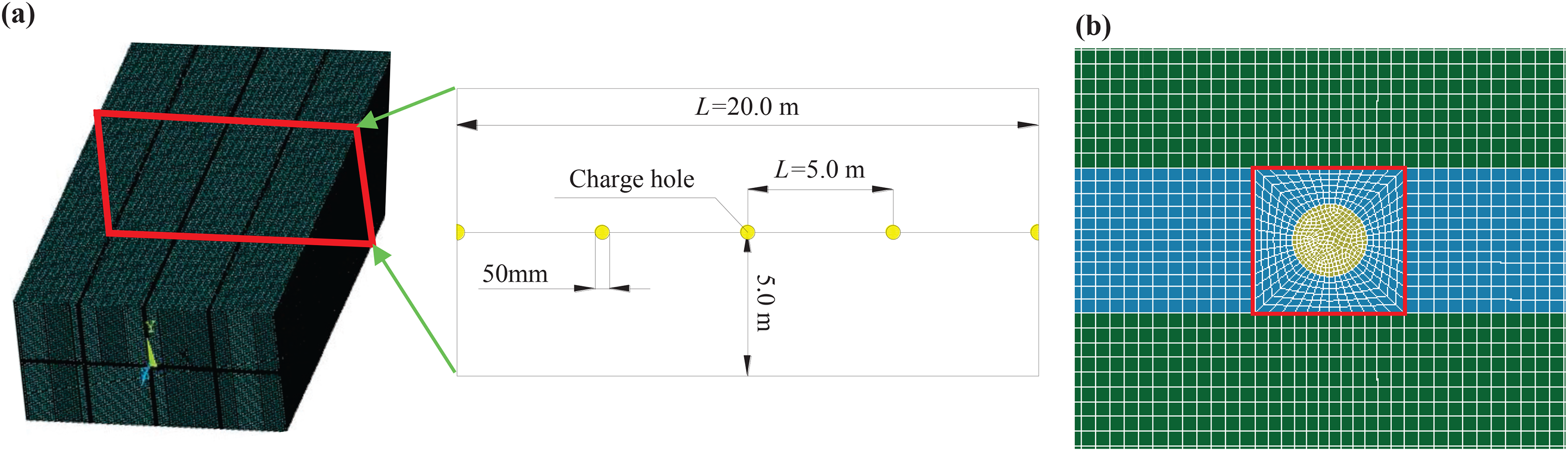
Model parameters of blasting holes: (a) model size and blasting hole arrangement and (b) grid around a blasting hole.
To avoid the problem of calculation interruption and reduced simulation accuracy induced by the severe distortion of the Lagrange element meshing during the blasting process, the partition of the rock mass and explosive in the modelling was meshed using Euler elements, and the multi-material ALE algorithm was used, which allows element deformation and explosive detonation product diffusion. According to related research results, the numerical model and field application adopted the Class-2 coal mine permissible emulsion explosive (Gorgulu et al., 2015; Jessu et al., 2018). The kinematic hardening plastic model (MAT_PLASTIC_KINEMATIC) was employed to characterise the rock breakage and fracture process with the Cowper–Symonds high strain rate model.

Rock mechanical parameters.

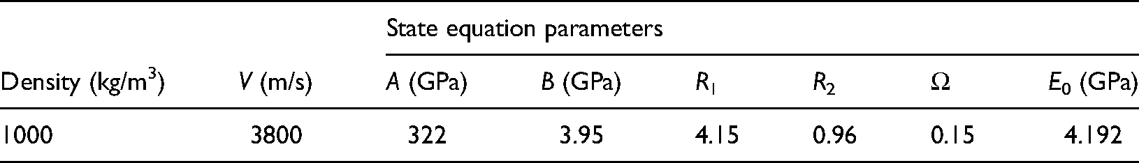
Explosive parameters.
MAT_ADD_EROSION parameters.
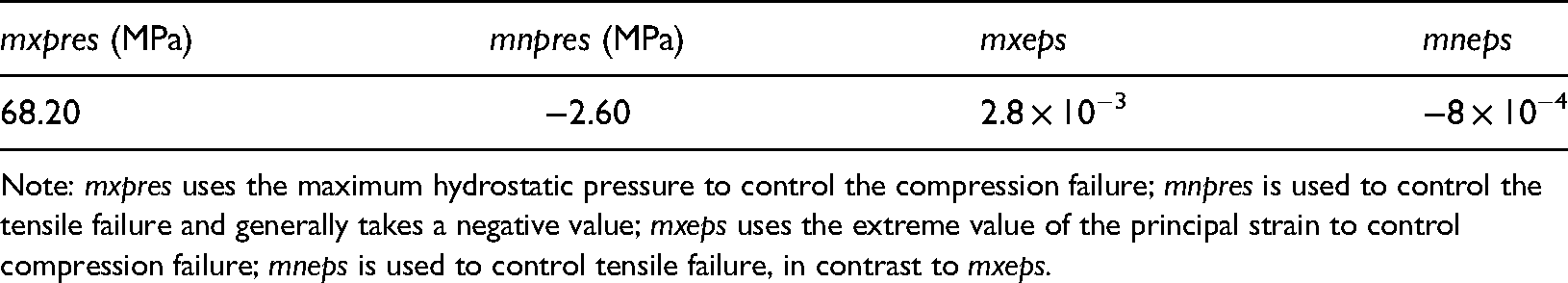
Note: mxpres uses the maximum hydrostatic pressure to control the compression failure; mnpres is used to control the tensile failure and generally takes a negative value; mxeps uses the extreme value of the principal strain to control compression failure; mneps is used to control tensile failure, in contrast to mxeps.
Determination of the charge structure and holes spacing
Determination of the charge structure: To obtain a good pre-splitting effect, the charge structure was determined based on the spatial distribution of the blasting-induced cracks. In the blasting simulation, the multi-directional cross-development density of cracks was characterised by the number of main-wing cracks at different positions in the fracture zone. In addition, the failure ratio of the rock mass unit in a rectangular area with the holes centre connection as the symmetry axis was used to quantify the overall degree of fracture damage of the THR in the main control direction of fracturing. The distribution of blasting-induced cracks under an uncoupled charge is shown in Figure 8, and the characteristic curves of rock fragmentation at different positions in the holes centre line are shown in Figure 9.
Distribution characteristics of blasting-induced cracks under different charge coefficients: (a) diagram of the main-wing crack distribution; (b) kr = 1.0; (c) kr = 1.25; (d) kr = 1.5 and (e) kr = 2.0.
Crack distribution and weakening curve under uncoupled charge blasting: (a) number of main-wing cracks at different locations relative to the blasting hole and (b) fracture degree of the rock mass between blasting holes.
In the vicinity of the blasting hole, the number of main cracks reached a peak value of 9 at kr = 1.11 (the damage degree showed a slight decrease at kr = 1.25). In the middle zone between adjacent blasting holes, the number of main cracks reached a peak at kr = 1.25, while the number of wing cracks reached a peak at kr = 1.25 and 1.5. The number of cracks shows that the cross-development of blasting cracks was significant between kr = 1.11 and 1.5, indicating that this range produced a better blasting fracture effect.
With respect to the degree of blasting fracturing, the variation trend was consistent for different radial decoupling coefficients. For the coupled charge, the crushing range near the blasting hole was most significant, but the cracking ability in the far zone of blasting decreased. Based on the degree of fracturing in the middle zone, the optimised uncoupled charge coefficients were kr = 1.11 and 1.25, that is, the charge diameters were 45.0 and 40.0 mm, respectively. Within the range of kr = 1.25–1.5, the dense development of blasting-induced cracks improved the possibility of multi-directional crack propagation in the damaged rock mass and induced more uniform blasting fragmentation, which is helpful for effectively releasing the stored energy during the secondary fracture process. When kr ≥ 1.5, there was a negative correlation between the blasting cracking degree and the uncoupled charge coefficient. Because the pre-splitting effects under kr = 1.11 and 1.25 were similar, considering the matching problem between the borehole diameter and charge as well as the reduction of the charge, the uncoupling coefficient was determined to be 1.25, that is, the diameters of the boreholes and charges were 50.0 and 40.0 mm, respectively. Compared with the full-thickness pre-splitting of the THR, the axial direction was determined to be the full-segment coupling charge.
Determination of blasting holes spacing: The determination of the blasting fracturing range is mainly based on the radius of the crushing-fracturing zone excited by the blasting shock wave and the quasi-static secondary driving crack radius of the explosive gas. Therefore, it is necessary to determine the shock wave stress near the blasting hole.
Considering the length of the sealing section and the cartridge positions, the blasting process can be simplified as a plane strain model of the shock wave. Based on dynamic compression failure of the rock mass near the blasting holes, the radius of the crushing zone (rc) is obtained as follows:
Because the rock is in the critical transition state between dynamic compression and dynamic tensile fracture at the interface between the crushing and fracturing zones, the development radius (rp) of the fractured zone can be calculated as follows:
Combined with the numerical results (kr = 1.25), the combined length of crushing-fracturing stable development was 2.11 m, that is, rc + rp = 2.11 m.
For the quasi-static secondary driving crack radius of the explosive gas, the relationship between the maximum length of the secondary cracks induced by the detonation gas, lk(max), and detonation pressure, px, was derived as follows:
As can be seen from equation (17), Px is positively correlated with lk(max). Based on the number of main cracks of n = 4–10 in the mathematical model (Garnsworthy, 1990), combined with the simulation results (n = 8, kr = 1.25), lk(max) could be obtained as lk(max) = 0.43 m under the condition of n = 8. Therefore, to improve the development degree and range of fracturing in the far blasting zone, the optimal distance between adjacent blasting holes was set at 5.0 m.
Analysis of blasting fracture numerical results
The DPB model was employed to analyse the fracture evolution and zoning characteristics of the blasting holes, as shown in Figure 10.
Evolution and distribution of fractures: (a) 140.8 μs; (b) 329.4 μs; (c) 416.3 μs and (d) 541.3 μs.
Figure 10(a) depicts the morphology of the crushed zone (Rc = 0.13 m), while Figure 10(b) shows the fracturing process induced by stress wave arrest and crack secondary propagation driven by the detonation gas, which yielded a value of Rp = 1.95 m. The simulation result that Rc + Rp = 2.08 m is consistent with the calculation result of rc + rp = 2.11 m. As seen in Figure 10(c), in the process of detonation gas diffusion, the main and wing cracks were cross-developed and interconnected, while the wing crack propagation was dominant. Figure 10(d) illustrates the fractures in the middle region, where a weakening zone with a minimum height of 0.40 m was formed.
Figure 11 shows the fracture distribution in blasting weakening zone with different hole depths.
Blasting-induced fracture variation with different hole depths: (a) 5.0 m; (b) 8.0 m; (c) 10.0 m and (d) 15.0 m.
As shown in Figure 11, the wing cracks around the symmetry axis accelerated the fracture development and reduced the fragmentation lumpiness of the pre-split rock. At different depths, the minimum width of the wing crack weakened zone was 0.4 m (range: 0.40–0.44 m). Combining fracture development and fragmentation statistics, the rock block length was determined to be 0.2 m. Based on the symmetrical distribution of wing cracks, the block width was assessed as 0.2 m. Therefore, the fragmentation size in the pre-splitting zone was set at 0.2 m × 0.2 m in the universal distinct element code (UDEC) models. Meanwhile, the simulation results confirmed that the determined structural parameters of the charge could ensure a favourable pre-splitting effect.
Discrete element analysis of pre-splitting controlled roof caving
UDEC software (a two-dimensional, discrete element numerical calculation program appropriate for non-continuum modelling) was employed to establish different models to investigate the controlled THR caving (Marko et al., 2017). The model had dimensions of 140 m × 80.7 m. To eliminate the boundary stress concentration, the boundary pillar width was set as 30.0 m. The side and lower boundaries had fixed displacements, and the overburden was simplified as a uniformly distributed loading applied to the upper boundary. The Mohr–Coulomb criterion was used for the material and joint strength assessment. After the model was initially balanced, the blasting pre-splitting zone was reassigned with the weakened joint parameters 30 m in front of the coal wall, and then coal circulation excavation was carried out. Based on the fracturing characteristics obtained with LS-DYNA, the fragmentation in the middle weakening zone was determined in a region of 0.2 m × 0.2 m.
Combined with the critical relationship between periodic pre-splitting intervals and angles, three UDEC simulation schemes were realised: (i) THR with non-periodic pre-splitting, (ii) a pre-splitting interval of 10.0 m with a zero rotation angle and (iii) a periodic interval of 8.0 m with a horizontal rotation angle of 7°, as shown in Figure 12(a) to (c), respectively. The strata movement characteristics under different pre-splitting parameters are shown in Figures 13 to 15.
Universal distinct element code (UDEC) simulation schemes: (a) model division and lithology distribution; (b) non-periodic pre-splitting; (c) periodic pre-splitting interval of 10.0 m; (d) periodic pre-splitting interval of 8.0 m.
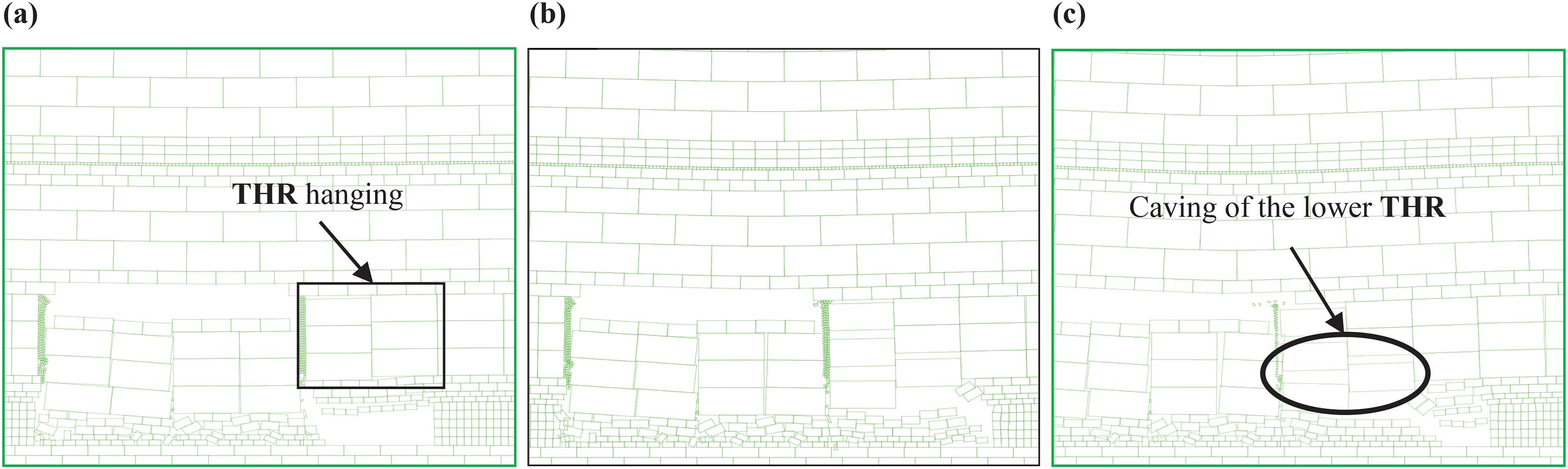
Fracturing characteristics of thick-hard roof (THR) without pre-splitting: (a) THR hanging (length: 20 m); (b) caving of the lower THR and (c) hanging of the upper THR.
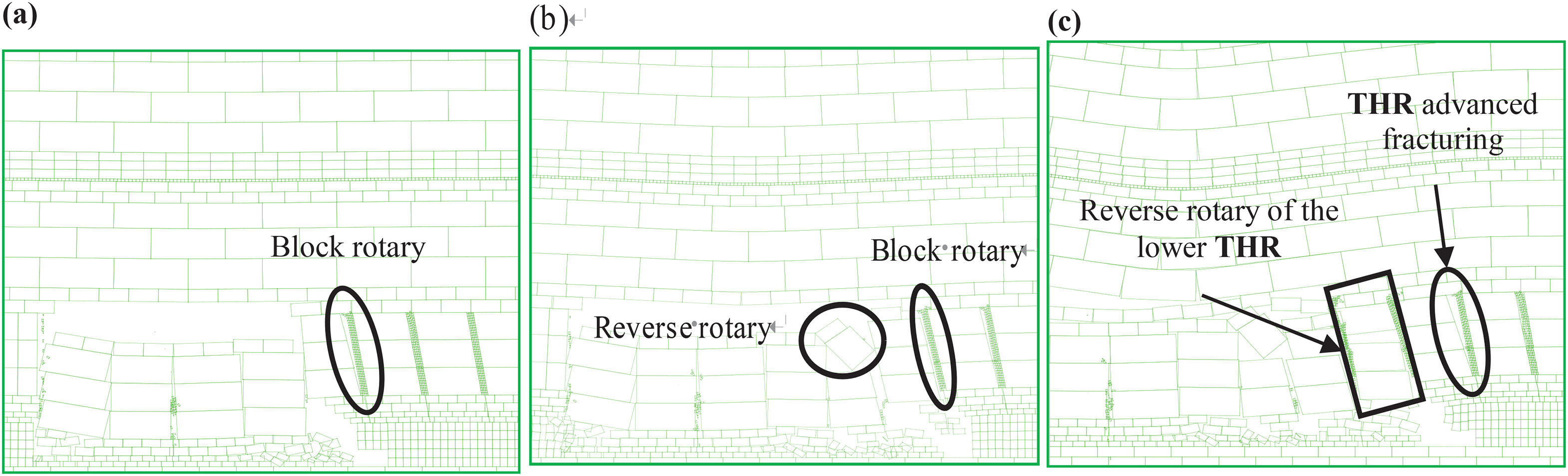
Fracture characteristics with a periodic pre-splitting interval of 8.0 m and angle of 7°: (a) periodic caving of pre-split thick-hard roof (THR) (first); (b) second periodic caving and (c) advanced fracturing and rotation of pre-split THR.
As shown in Figure 13, after the initial collapse, the THR utilised the coal mass as the supporting part and could be reduced to the cantilever beam structure, with small bending and rotation. In the mining process, the non-pre-split THR had a large suspended roof area. Advanced to 56 m, the lower layer of the THR induced delamination separation and collapse. At 66 m, the THR generated a general rotation, with the first periodic interval of 30 m. During the mining period, the support bore a high compressive pressure, which exceeded the rated resistance of the support. Consequently, the working face was susceptible to support crushing, and threatened the safety of coal production.
As shown in Figure 14, with a periodic pre-splitting interval of 10.0 m, when the working face was advanced to 46 m, the THR produced a micro-rotation under the action of the overlying loading, which had no evident influence on the supports. The THR then completed the first periodic caving along the blasting fracture zone. At 56 m, the THR induced the second periodic instability, which presented an apparent shear falling in the surface corresponding to the pre-splitting zone. The overall shear falling jeopardised the safe operation of the supports.
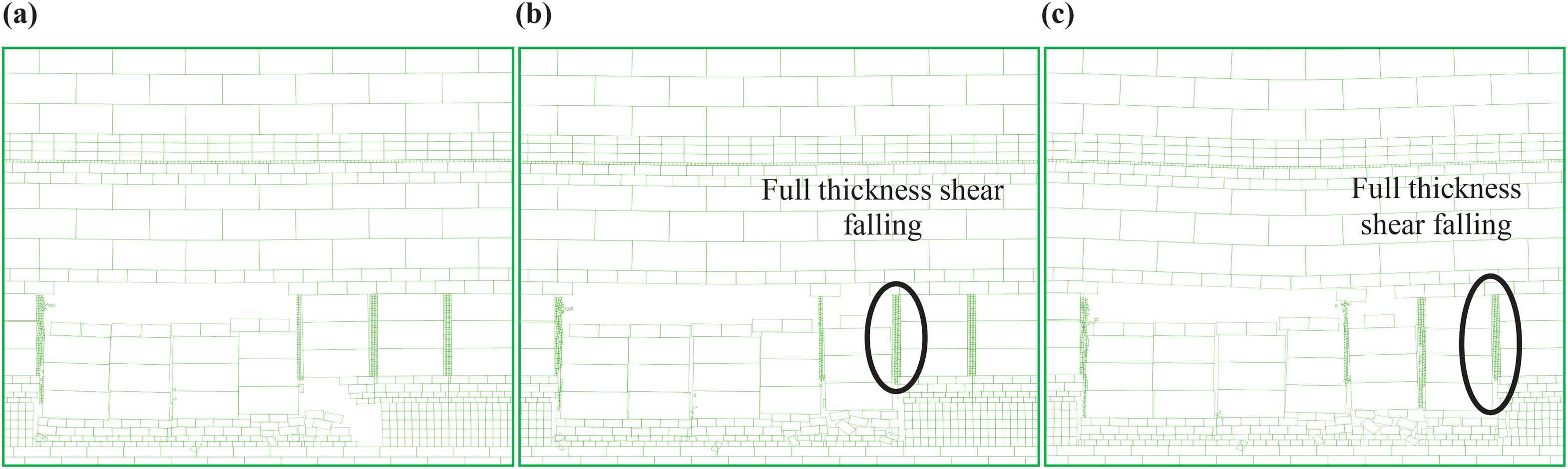
Fracture characteristics with a periodic pre-splitting interval of 10.0 m and a zero angle: (a) pre-splitting roof hanging; (b) first shear falling of pre-split thick-hard roof (THR) and (c) second shear falling.
As shown in Figure 15, with a pre-splitting interval of 8.0 m, when the working face was advanced to 48 m, the THR broke down within the first periodic interval. Meanwhile, the lower layer of the THR rotated, and the upper layer was unstable with reverse rotation. The THR then completed the second periodic breaking. In the process of the third recurrent instability, the fourth-period pre-splitting block induced fracture and micro-rotation ahead of the coal wall, which cut off the stress transfer route and released the excessive pressure acting on the supports. In the process of collapse, the THR presented a general reverse rotation instability, which reduced the transferred loading and avoided the shear instability of the pre-splitting block and crushing of supports.
Figure 16 shows the variation in the stress parameters with different pre-splitting intervals.
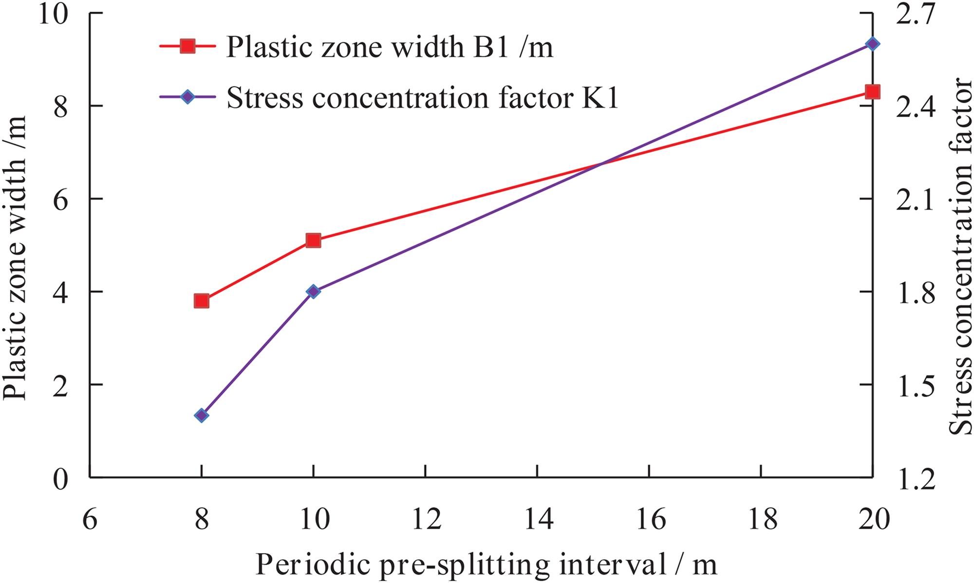
Variation in the stress concentration and failure characteristics with different periodic pre-splitting intervals.
For the plastic zone width, B1, with an increase in the pre-splitting interval, B1 was positively correlated overall, but the growth rate was higher in the range of 8.0–10.0 m, which strongly indicates that the control of the stress peak position was more significant for the interval of 8.0 m. Meanwhile, the variation in K was consistent with that of B1. The above results made it possible to assess the optimal pre-splitting interval/angle combinations that yield the most effective stress concentration reduction.
The UDEC simulation results revealed that as the working face advanced near the pre-splitting line, the fracturing of the THR controlled by DPB could collapse in a timely manner with a periodic interval of 8.0 m and properly alleviate the influence of strata behaviour on the working face, according to the morphology change of the THR rotation instability and reduction of the abutment stress peak. The above results show that DPB with optimised parameters has dual effects of weakening the mechanical properties of THR and optimising the fracture structure of the strata.
Field application and engineering measurements
Technological parameters of the pre-splitting blasting
Combining the theoretical analysis and simulation results, the technical parameters of DPB were designed and implemented. The arrangement of the blasting holes is shown in Figure 17.
Illustration of the on-site blasting pre-splitting parameters.
For the DPB in 13.7 m of medium sandstone, the periodic pre-splitting interval was set as 8.0 m, and the rotation angle of the boreholes forming the plane was 7°. The diameters of the drilling and cartridge were 40.0 and 50.0 mm, respectively. The detonating cord was bundled to the first charge, which was placed at the bottom. In the sealing section, the plasticity (stemming) structure was used for shock wave buffering, and the rigid structure resisted residual energy. To avoid the blasting affecting the abutment stress, the initiation location of the coal wall advance was no less than 40 m. The parameters of the blasting holes are listed in Table 5.
Technical parameters of the pre-splitting blast holes.
Note: The length of a single cartridge is 0.45 – 0.55 m.
Analysis of the support working resistance
After implementing pre-splitting blasting, the strata behaviour was analysed, as shown in Figure 18.
Strata behaviour characteristics (hydraulic support type: ZFS7500/22/35).
Figure 18 shows the THR caving with a ‘minor-major periodic weighting’ general pattern. When the working face was advanced to 37.6 m, the THR initially broke. Then, the THR collapse exhibited the ‘minor’ periodic weighting with a range of 6.7–9.8 m, which is basically consistent with the 8.0 m pre-splitting interval of the site blasting scheme. At 86.4 m, the support resistance reached its peak of 7388 kN, which corresponds to 98.5% of the rated value, resulting from the local strong pressure behaviour induced by the initial collapse of the 14.2 m gritstone. Thereafter, the strata fracturing exhibited the ‘minor-major periodic weighting’ pattern with the maximum working resistance reaching 7125 kN, in which one major wave was usually accompanied by three to four minor waves. Accordingly, after pre-splitting, the control of THR fracturing had a noticeable effect, and the support resistance had an adequate margin of safety, ensuring safe production.
Effectiveness of blasting on THR control
After DPB in the technical roadway, the pre-splitting effect of the THR was analysed based on field observations. Figure 19 shows the deformation characteristics of the roadway before and after blasting pre-splitting.
Deformation and instability characteristics at different positions of the mining roadway with an advanced working face before and after pre-splitting: (a) advanced by 5.0 m before blasting; (b) advanced by 20.0 m before blasting; (c) advanced by 5.0 m after blasting and (d) advanced by 20.0 m after blasting.
As shown in Figure 19, before blasting pre-splitting, the floor deformation was quite severe, and the maximum floor heave was 1.2 m for the advanced working face of 5.0 m, with local roof collapse. The working face was advanced by 20.0 m, and the roadway was supported by timbering. However, the roadway deformation was still too large, resulting in the termination of normal operation. Under the condition of pre-splitting, the working face was advanced by 5.0 m, producing deformation of up to 0.5 m, and the roof was relatively stable. When the working face was advanced by 20.0 m, the roadside formed a partial coal wall, whereas the roof and floor were deformed only slightly, meeting the requirements for mining safety.
The above findings strongly suggest that DPB has an excellent technical effect on THR pre-splitting control.
Conclusion
Based on periodic fracture control of the THR using DPB technology, the following conclusions can be drawn:
A mechanical model of the cantilever beam and fracture-articulated structure was proposed for the THR, which allowed the derivation of the relationship between the partial loading and support resistance. The relationship between limited periodic controlling intervals and angles was determined to obtain the optimal periodic pre-splitting range of 8.0 m and rotation angle of 7°. LS-DYNA3D was used to illustrate the fracture evolution and interconnection of the main and wing cracks in different zones of the DPB. The fracture degree under the optimised blasting parameters in the middle weakening zone was analysed, demonstrating that cracks between adjacent holes were successfully pre-fractured. Meanwhile, the blasting-induced characteristics were determined, including the minimum fracturing-weakening width of 0.4 m and the average fragmentation of 0.2 m × 0.2 m. UDEC modelling was employed to compare the fracturing and instability morphologies of the pre-split THR under different control parameters. A favourable control effect was obtained with an optimal periodic pre-splitting interval of 8.0 m and an angle of 7° on the THR, showing a significant reduction in the plastic zone width and stress concentration factor of the advanced abutment pressure. The DBP effect could weaken the mechanical properties of the pre-split rock and optimise the fracture structure. The DPB technological parameters were optimised and applied to the 309 Panel in Xinzhouyao Mine. The periodic caving interval of the THR was controlled successfully, accompanied by the blasting pre-split roof experiencing a timely collapse. The working resistance of the support was significantly reduced with sufficient allowance, and the deformation of the mining roadway under advanced support pressure was significantly improved. A remarkable technical effect was obtained.
Footnotes
Acknowledgements
The authors would like to thank all editors and anonymous reviewers for their comments and suggestions.
Declaration of conflicting interests
The authors declared no potential conflicts of interest with respect to the research, authorship and/or publication of this article.
Funding
The author(s) disclosed receipt of the following financial support for the research, authorship and/or publication of this article: This work was supported by the Educational Commission of Anhui Province (grant no. KJ2020A0320), National Key Research and Development Program of China (grant no. 2020YFB1314203), Independent Research Fund of the State Key Laboratory of Mining Response and Disaster Prevention and Control in Deep Coal Mines (Anhui University of Science and Technology) (grant no. SKLMRDPC19ZZ11) and Key Program of Scientific Research Fund for Young Teachers of Anhui University of Science and Technology (grant no. QN2019112).
Data availability
The data used to support the findings of this study are available from the corresponding author upon request.