
Abstract
In the mining of close coal seam, the stress concentration under the residual coal pillar in the upper coal seam leads to serious deformation to roadway surrounding rock in the lower coal seam. Hence, it poses a huge challenge to the maintenance of entry surrounding rock. Based on this, an approach of entry surrounding rock control technology, directional pre-splitting, and roof-cutting pressure relief, was applied. The stress and deformation of entry surrounding rock utilizing directional pre-splitting and roof-cutting pressure relief were studied by numerical simulation and field test The results indicated that the depth of stress concentration under the residual coal pillar achieve 44 m. With the application of the roof presplitting, the vertical stress of the entry roof decreased. Utilizing the roof presplitting with a height of 7 m and an angle of 15°, the gangue filled the goaf and supported the overlying strata. Meanwhile, the surrounding rock of entry was controlled with a constant resistance anchor cable (9 m length) and gangue prevention support structure. Through field test monitoring, the roof pressure and the deformation of surrounding rock increases rapidly at 30 ∼ 110 m behind the working face. From 110 ∼ 160 m, the increased rate of roof pressure and surrounding rock deformation gradually slows down and tends to be stable at 160 m behind the working face. The maximum displacement of the roof to the floor is 511 mm, and the maximum displacement of the gangue rock wall to coal wall is 421 mm. The remaining roadway meets the demand of the adjacent working face.
Introduction
Coal is important non-renewable fuel energy that contributes to the growth of the economy around the world, and up to 30% of the total energy consumption comes from coal. (Gao, Wang, et al., 2019) For instance, the coal output reach 3800 million tons in China in 2020, of which 55% was used for energy consumption. (Zhang, Pak, et al., 2020) Therefore, coal mining plays a significant role in the development of the economy in China. However, with the high-intensity exploitation in recent years in China, the reserves of coal seams that are easily minable in many mining areas are diminishing continuously. (Zhu, Yao, et al., 2020) The coal reserves with the less favorable geological condition, such as close coal seams, are coming into focus. (Feng and Wang, 2020, Gao, Zhang, et al., 2020, Sushe and Weibing, 2016, Wang, Chang, et al., 2018) Due to the widely distributed and abundant reserves in China, the mining of close coal seams is regarded as an effective means to improve the recovery of coal resources.(Zhu, Yao, et al., 2020, Li, He, et al., 2020, Shang, Ning, et al., 2019)
Based on the explanation in “Coal Mine Safety Regulation” (2016 Edition) in China, the close coal seams can be defined as “coal seams that have a small distance and can be significantly affected by the mining of upper or lower coal seams”. The most commonly used mining method for multi-seam is longwall coal mining following a downward mining sequence, during which the mining method of the upper coal seam is the same as that of a single coal seam.(Li, Wang, et al., 2019, Song and Konietzky, 2019, Tan, Liu, et al., 2017, Wang, Wei, et al., 2019, Zhao, Guo, et al., 2018) In the traditional multi-seam longwall mining method, one coal pillar and two mining roadways are required in each working face. (Wang, Yang, et al., 2019, Zhen, Gao, et al., 2019) Therefore, when the upper coal seam had been mined, massive residual coal pillars and goaf were left. (Shang, Ning, et al., 2019) Consequently, a stress concentration area was formed under residual coal pillars, while the degree of stress concentration decreases with the increase of distance from the center of the coal pillar. (Zhang, Yang, et al., 2008) Thus, the stress distribution of the overlying strata of the lower coal seam was heterogeneous, which cause horizontal tensile stress. (Zhang, Zhang, et al., 2018, Kong, Wang, et al., 2014), The overlying strata of the roadway in the lower coal seam exists in large deformation subjected to the horizontal tensile stress. (Huang and Han, 2019, Ju, Xu, et al., 2015, Peng, Gao, et al., 2019, Xie, Sun, et al., 2016) This poses a huge challenge in roadway arrangement and formulating control measures of roof strata of the lower coal seam.
Over the past decades, a number of researches have been conducted by scholars that aim to understand the floor stress distribution and entry stability control of lower coal seams under residual coal pillars. (Ning, Wang, et al., 2020, Shen, Dou, et al., 2017, Wang, Xu, et al., 2019, Zhu and Tu, 2017, Zhang, Yang, et al., 2008) investigated the stress distribution law of floor under coal pillar by means of the numerical simulation method, which depicted that the stress distribution of floor under residual coal pillar show obvious heterogeneous characteristics. The same conclusion was also obtained by Zhang Wei, et al.(Zhang, Zhang, et al., 2018) and Kong Dezhong, et al.(Kong, Wang, et al., 2014) Based on the analysis of this heterogeneous stress distribution, the reasonable position of the roadway in the lower coal seam was determined. Yan, et al.(Yan, Weng, et al., 2015) constructed a mechanical model to study the horizontal, vertical, and tangential stress equations of the floor under residual coal pillars, which obtained reasonable supporting parameters for roadway in the lower coal seam. Yu Yang, et al.(Yu, Shen, et al., 2016) provided three-dimensional combined roof control techniques based on hydraulic expansion bolt and advancing insertion of the tube on the roof. The corresponding key parameters are determined through theoretical analysis and field tests. Zhang Wei and Fang Xinqiu (Fang, Guo, et al., 2009, Zhang, Zhang, et al., 2012) studied the determination of the reasonable position of the roadway in lower coal seam according to the stress state. Ju and Xu (Ju and Xu, 2013, Ju, Xu, et al., 2015) proposed that when the coal pillars are out of the working face of the lower coal seam, the braking distance of the overlying main roof is related to the distance between the opening of the lower coal seam working face and residual coal pillar. In conclusion, previous studies (Gu, Li, et al., 2020, Guo, Gong, et al., Hao, Wu, et al., 2019, Kang, Sun, et al., 2010, Li, Ding, et al., 2016, Pan, Kong, et al., 2014, Suo, Tielin, et al., 2013) have already provided some useful experimental results in instability mechanisms and prevention of roadway under residual coal pillar in lower seam. However, most of these studies only focus on the layout and reinforcement support parameters of roadway, such as arranging the roadway away from the stress concentration area caused by the residual coal pillar, increasing the dimension of coal pillars, and enhancing the supporting structure of roadway. This lead to the waste of coal resources and higher cost in roadway supporting. Meanwhile, the horizontal tensile stress in the overlying strata of lower coal seam which caused by heterogeneous stress distribution does not eliminate. Hence, the deformation of roof strata of roadway in lower seam still serious due to the couple effect of stress concentration caused by residual coal pillar of upper coal seam and mining disturbance of lower coal seam.(Zhang, Yang, et al., 2008, Kong, Wang, et al., 2014)
From the discussion above, the primary problem that requires to be settled in controlling roof strata in the lower coal seam is to decrease or eliminate the transmission of horizontal stress in roof strata. In view of this, a technological innovation that can cut off the transfer of horizontal stress in roof strata, gob-side entry retention by roof presplitting (GERRP) based on the short-arm beam theory was put forward by He et al.(He, Song, et al., 2017, He, Xie, et al., 2005) in 2008. GERRP, one of the most important technology innovations in the last decades, has been successfully tested in many mines and experimental studies.(Gao, Liu, et al., 2017, He, Gao, et al., 2017, Hu, He, et al., 2019, Ma, He, et al., 2021, Ma, Wang, et al., 2018) The core of this technology is to carry out directional pre-splitting blasting along the goaf side of the entry roof in the working face mining advance direction under the condition of roof strengthening with high pre-tightening force constant resistance large deformation anchor cable (CRLDAC). Then, the horizontal stress transfer between the goaf roof and entry roof can be cut off in the vertical roof cutting range. After the advance of mining, the goaf roof will collapse and the gangue can fill the goaf effectively due to the bulking coefficient. This technology decreased the effect of horizontal stress caused by the residual coal pillar of the upper coal seam, released the pressure from roof strata, and improved the stability of the retaining roadway in the lower coal seam. Meanwhile, GERRP realizes the entry retaining automatically without any coal pillars and other filling materials, which increases the efficiency of entry retaining and reduces the cost First used in Baijiao Coal Mine of Sichuan province in China in 2010, GERRP has been widely used in hundreds of mines in China with variation geological conditions, such as thin and thick coal seam,(He, Gao, et al., 2017, Gao, Yang, et al., 2017, Guo, Wang, et al., 2016, He, Gao, et al., 2018, Sun et al., 2014) shallow and deep, (Ma, Wang, et al., 2018, He, Ma, et al., 2018, Wang, Gao, et al., 2018)composite and hard roofs. (He, Ma, et al., 2018, Wang, He, et al., 2018, Ma, He, et al., 2018) However, no studies have been performed on the application of GERRP in close coal seams under residual coal pillars.
In this paper, a case study by means of GERRP in the Taiping coal mine (Yunnan Province, China) with a close coal seam under residual coal pillar of the upper coal seam was investigated in theory analysis, numerical simulation, and practice. The main objective of this study is:
− To analyze the stress distribution in overlying strata under residual coal pillar. − To propose the key technology of GERRP and study the influence of the new technology on the overlying strata of roadway in lower coal seam under residual coal pillar by means of numerical simulation. − To study the overlying strata pressure characteristics of roadway in lower coal seam under residual coal pillar in practice.
Mining and geological condition
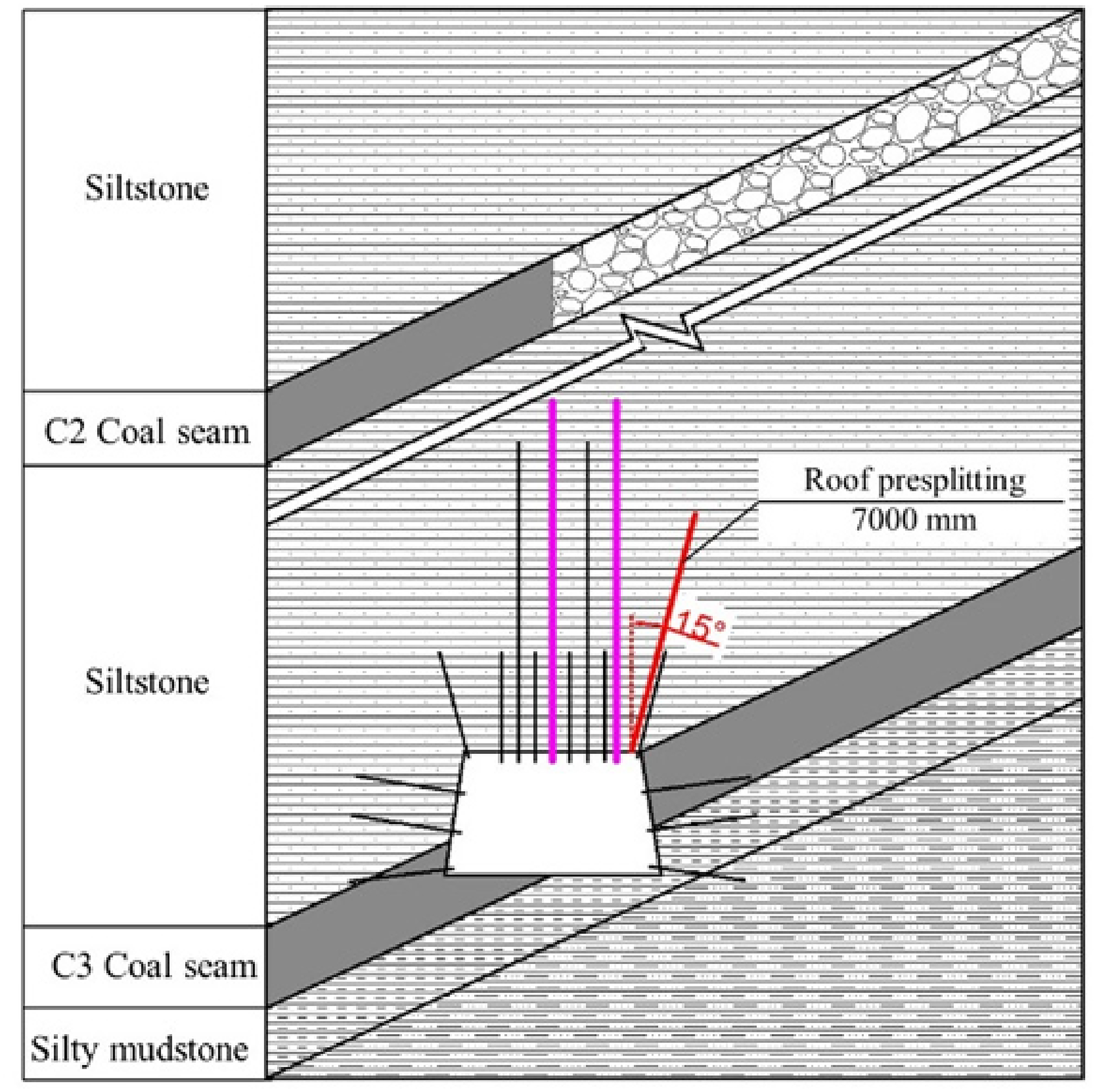
The case study coal mine is the Taiping mine located in the Xuanwei, Yunnan Province, China. The annual production capacity is 300,000 tons. The coal mine area is 2.0695 km2 with a surface level of + 1770m~ + 1500m. Based on the gas emission, the Taiping mine is defined as a low gas mine. The comprehensive geological histogram is shown in Figure 1. The overlying strata of coal seam 2# are silty stone with a thickness of 10 m, while the overlying strata of coal seam 3# are silty stone with a thickness of 13 m. The rock stratum below coal seam 3# is silty mudstone with a thickness of 6 m. The average thickness of coal seam 2# and 3# are 1.44 m and 1.76 m respectively. Currently, the coal seam 2# has been mined out in 2020, and a residual coal pillar was left. The coal seam 3# has a dip angle ranging from 20–32° with an average value of 28°and has a depth ranging from 243 to 310 m with an average value of 258 m. The length of the working face of coal seam 3# is 540 m. Then the working face 110301 in coal seam 3#, 125 m in length, was mining by means of the GERRP technology and still in process.
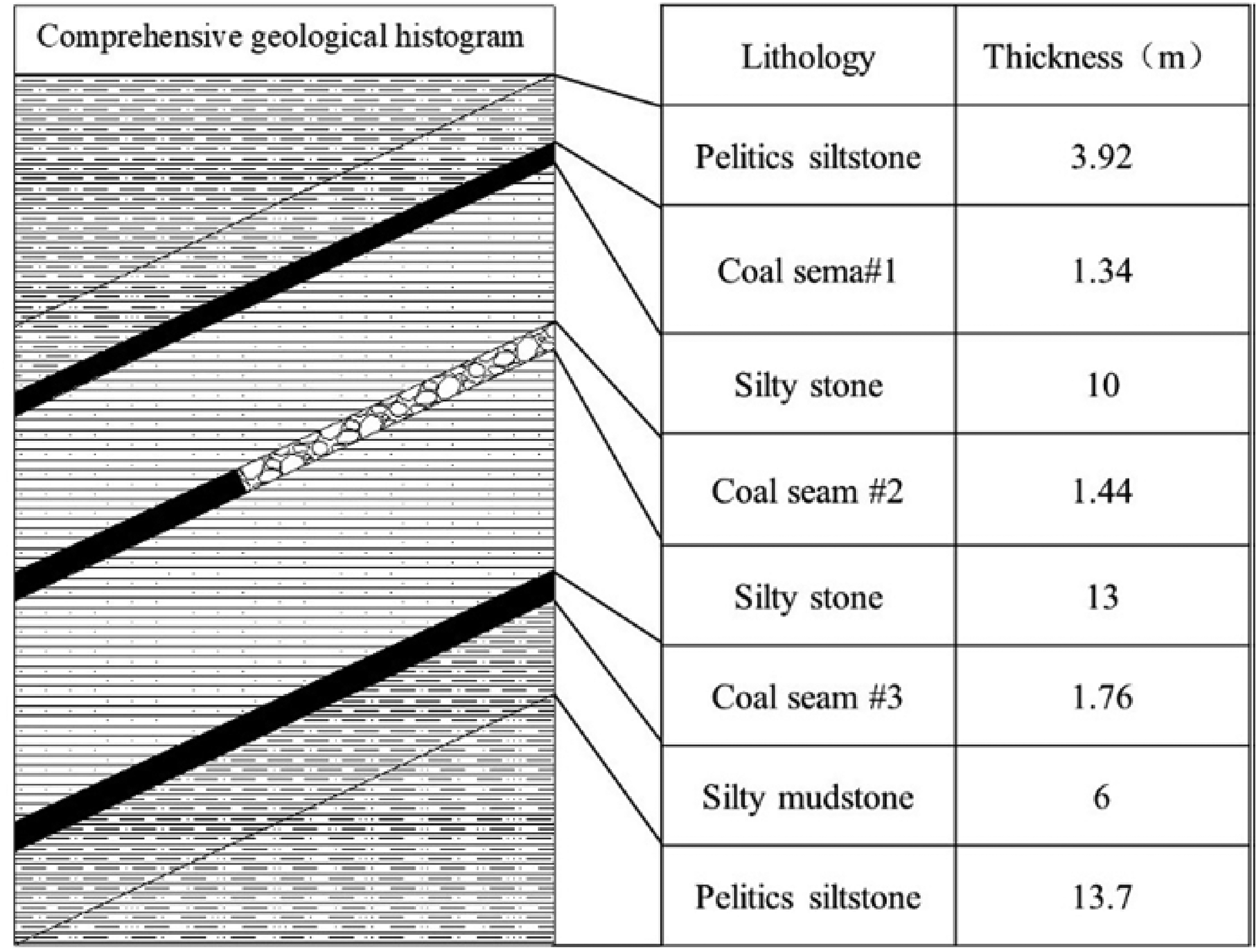
The comprehensive geological histogram of the case study coal mine.
Figure 2 shows the spatial location relationship of 2# and 3# coal seam. According to the space location relationship with the strike direction of the working face, the types of residual coal pillars in the close-distance multi-seam mining are diagonal coal pillars. Diagonal coal pillars intersect with the entry in the lower coal seam at an angle of 5° approximately.
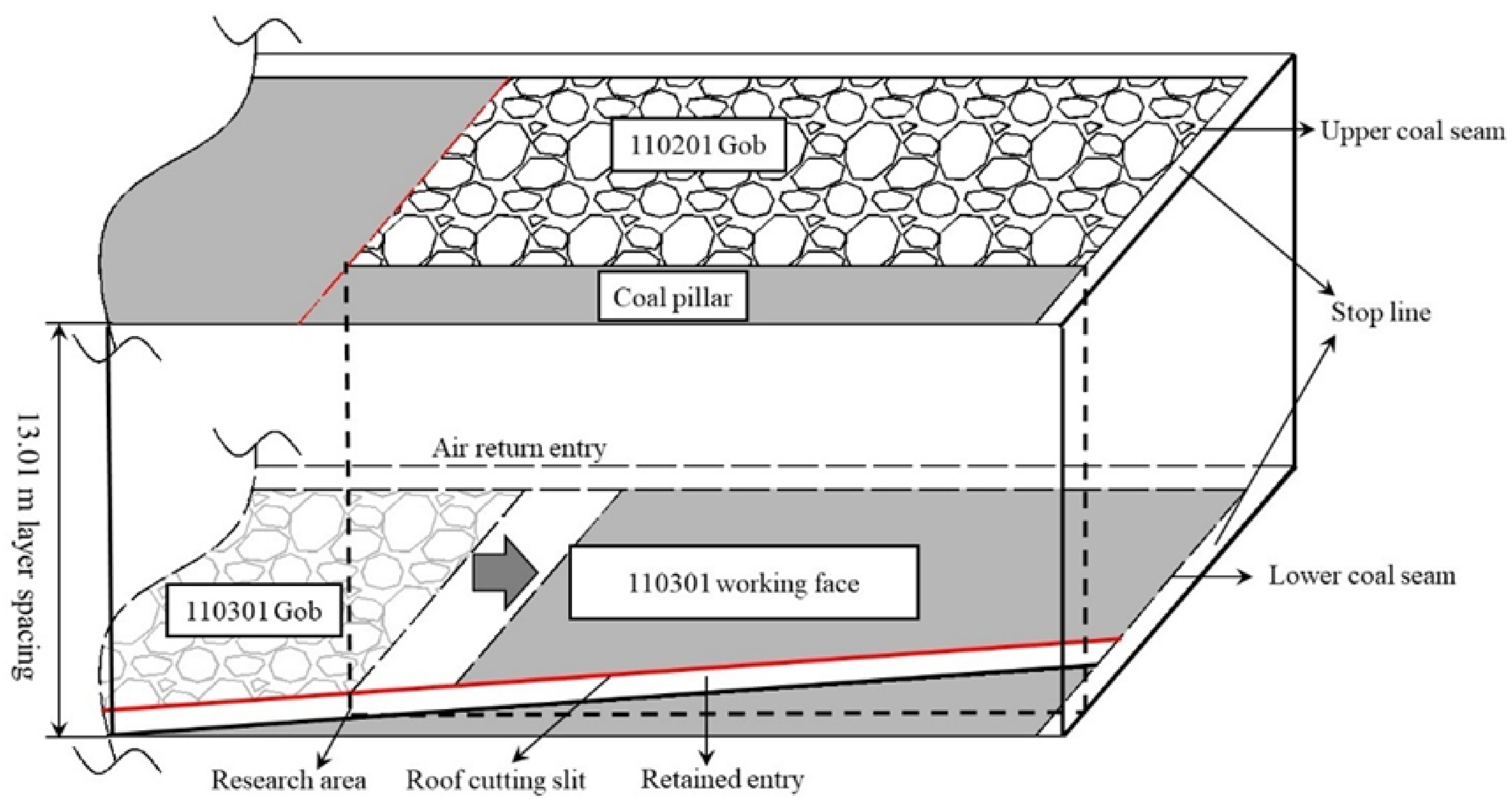
Space location relationship of C2 and C3 coal seam.
According to the calculation method of elastic foundation in soil mechanics(Zhao, Hebblewhite, et al., 2000) and the mine pressure theory of coalface overburden (Kong, Wang, et al., 2014), the failure depth of the floor under the coal pillar can be calculated by the following theory. The stress distribution under the coal pillar can be illustrated in Figure 3. The depth of the floor is defined as

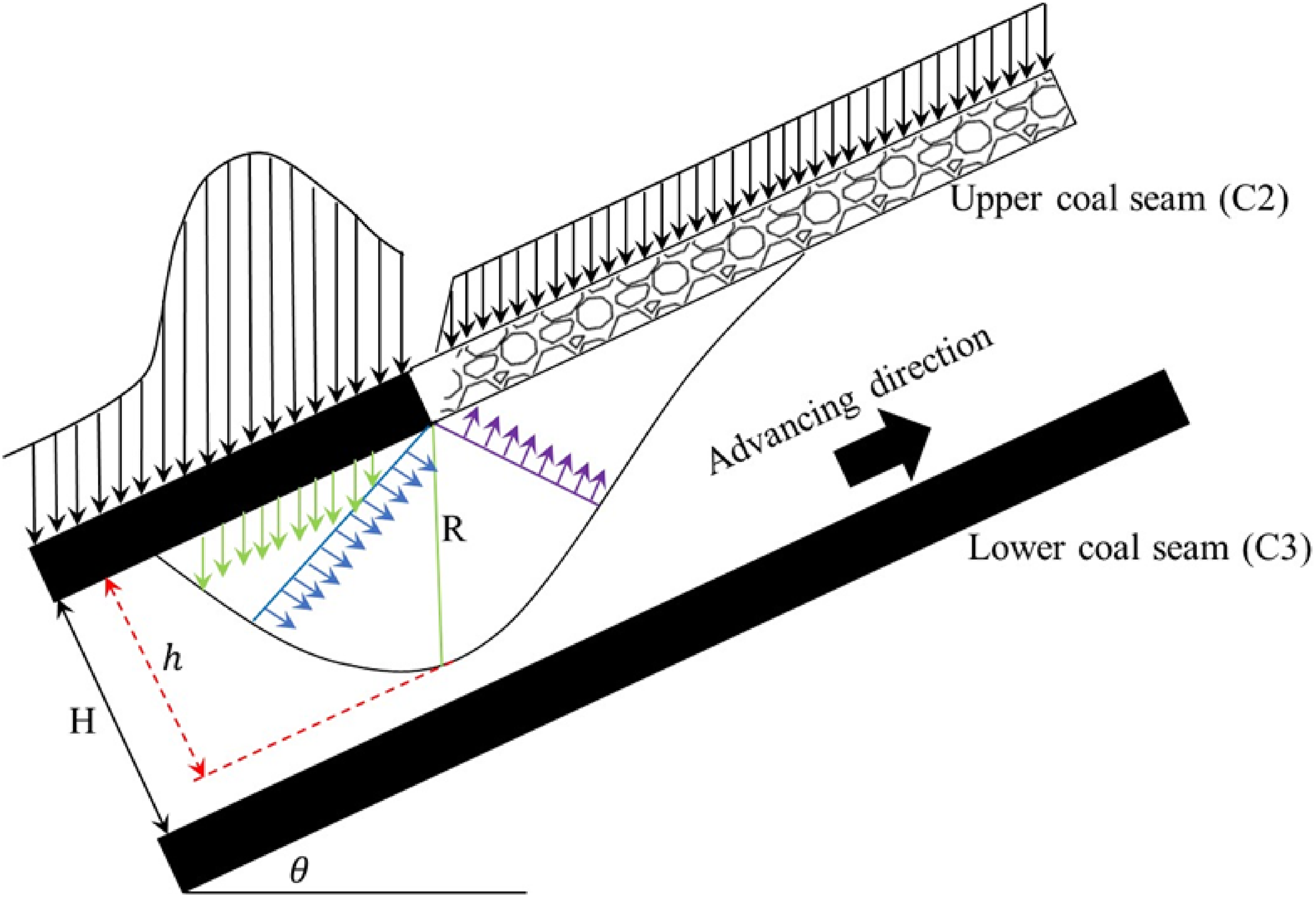
Distribution of stress under residual coal pillar.


Where
Define


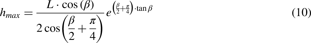
According to the field test, the internal friction angle of siltstone is 30°, L is 30 m. So that the maximum of failure depth of floor under coal pillar is:

Method and technology of GERRP
GERRP principle
In conventional longwall mining, two entries are driven mainly used for transportation and ventilation before the extraction of the working face. When the first working face is worked out, the entries are abandoned due to the collapse of the roof strata. Then, two new entries are needed to be driven for serving the next working face. Meanwhile, a protection coal pillar is set between two adjacent working faces, see in Figure 4a. However, in the application of conventional longwall mining to the multi-seam coal mine, the strong vertical stress and horizontal stress in roof strata caused by residual coal pillar in upper coal seam and mining activities in current coal seam hardly to release. Thus, it poses a huge challenge to the maintenance of the entries. Moreover, the high ratio of entry drivage contributes to the high cost of mining. In addition, the coal pillar that remained in the current coal seam leads to resource waste. Furthermore, it caused a stress concentration area on the floor thus affecting the mining of the next lower coal seam.
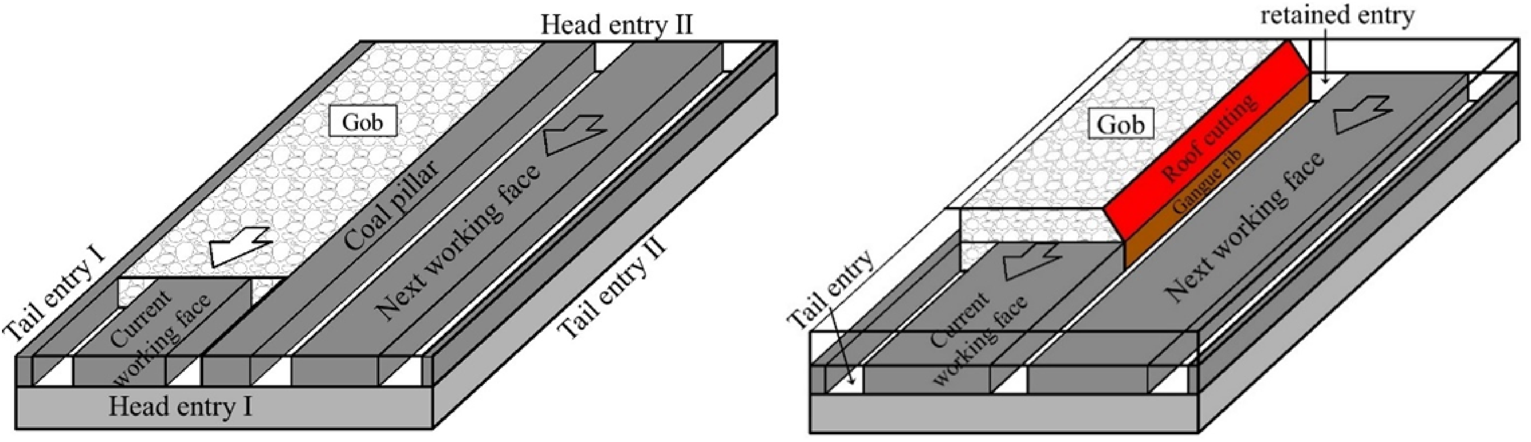
Conventional longwall mining and GERRP mining method.
The GERRP is an innovative non-pillar longwall mining method. As shown in Figure 4b, in the GERRP mining method, one of the roadways in the current working face is retained by means of roof splitting and reinforced support for servicing the next working face. The roof rock over goaf slips down into gangue along the splitting plane, during which the gangue prevention structures are built to prevent gangue from entering into the roadway. According to the breaking expansion coefficient of roof rock, the bulk gangue fills the goaf then forms one sidewall of the entry. With the application of the GERRP mining method, the horizontal stress in roof strata caused by residual coal pillar in upper coal seam as well as mining activities in the current coal seam is cut off through the splitting plane. Furthermore, a coal pillar and one of the entries-drivage are eliminated, thus contributing to the increase in economic benefits.
Technology process
To overcome the stress concentration caused by residual coal pillar and mining disturbance current coal seam. The main technology processes applied to the 110301 working face in the Taiping mine are shown in Figure 5a-f.
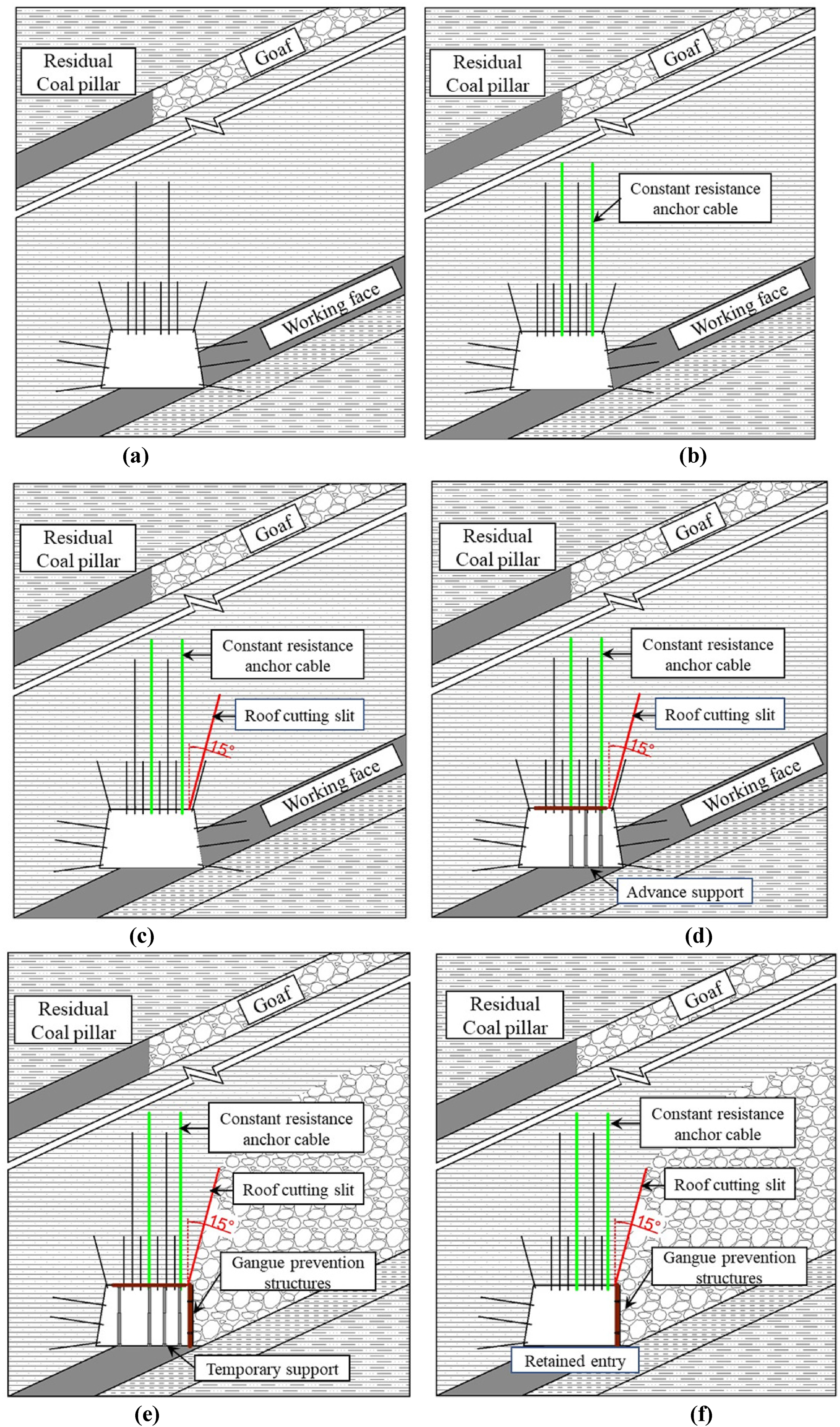
Technology process of GERRP.
Step I Installing the constant resistance large deformation anchor cable (CRLDA) during the entry excavation or before the recovery of the mining face, as shown in Figure 5b.
Step II: According to the design parameters, the drilling holes are carried out on the roof at the mining side. A new technology called directional pre-split cumulative blasting (DPCB) is used for cutting the roof strata, as shown in Figure 5c.
Step III: The advanced temporary support, two rows of single hydraulic prop, are implemented ahead of the working face 50 m approximately, as shown in Figure 5d.
Step IV: Installing the temporary support behind the longwall working face, 4 rows of single hydraulic prop, to support the roof of entry. Meanwhile, gangue prevention structures and metal nets are used to prevent the gangue from extending out into the entry. Then, the bulk gangue fills the goaf and forms one sidewall of the entry. In order to prevent the air from leaking, high polymer materials are sprayed on the surface of the gangue wall, as shown in Figure 5e.
Step V: When the goaf roof collapse is complete and the roof strata of retained entry are stable, the temporary support behind the longwall working face can be withdrawn for recycling. Then the entry is completely retained, as shown in Figure 5f.
Numerical simulating effect of GERRP on the stress evolution
Numerical model
Continuous-medium software FLAC3D, which is widely used to investigate the rock mechanics and engineering problems,(Meng, Xu, et al., 2020, Yin, Wu, et al., 2021, Zhu, He, et al., 2021) is applied to simulating investigate the effect of GERRP on the stress distribution and deformation property of the surrounding rock of retained entry in the lower coal seam. The numerical model with a dimension of 200 m × 300 m × 160 m (length × width × height) was established based on the geological condition of 10103 working face in the Taiping Mine as described in section 2. In this model, the thickness of coal seams 2 and 3 is 1.5 m and 1.8 m respectively. The distance between coal seams 2 and 3 is 13 m. The basic mechanical parameters of overlying strata in this model are shown in Table 1. The innovative approach GERRP was simulated by applying a null unit with a width of 0.05 m and length of 7 m, as roof presplitting simulation, as shown in Figure 6. Meanwhile, the original approach was simulated as a control group. In this study, the Mohr-Coulomb model was used as the constitutive model. Then, the working face was excavated for 200 m. According to the described above, the processes of the simulation were as follows: (a) assigned the mechanical parameters to the rock strata according to Table 1; (b) fix the boundary of the model except for the upper boundary; (c) apply an initial vertical and horizontal stress of 3.6 Mpa to the boundary of the model; (d) excavate the C2 coal seam which remanent a boundary pillar and solved; (e) excavate the entry in C3 coal seam and solved; (f) fracture the roof with a depth of 7 m and angle of 15°; (f) excavate the C3 coal seam.
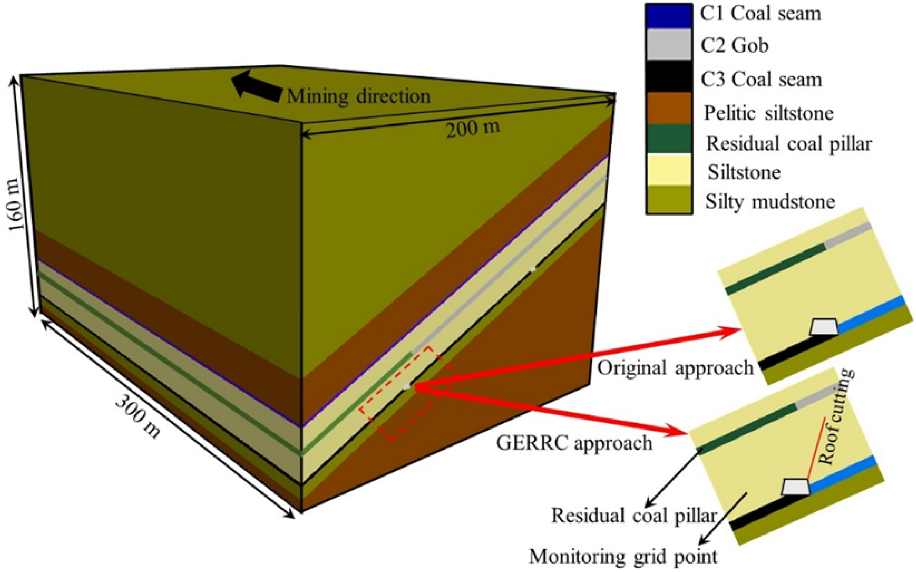
Schematic diagram of the numerical model in this study.
Mechanical property of overlying strata used in the numerical model.
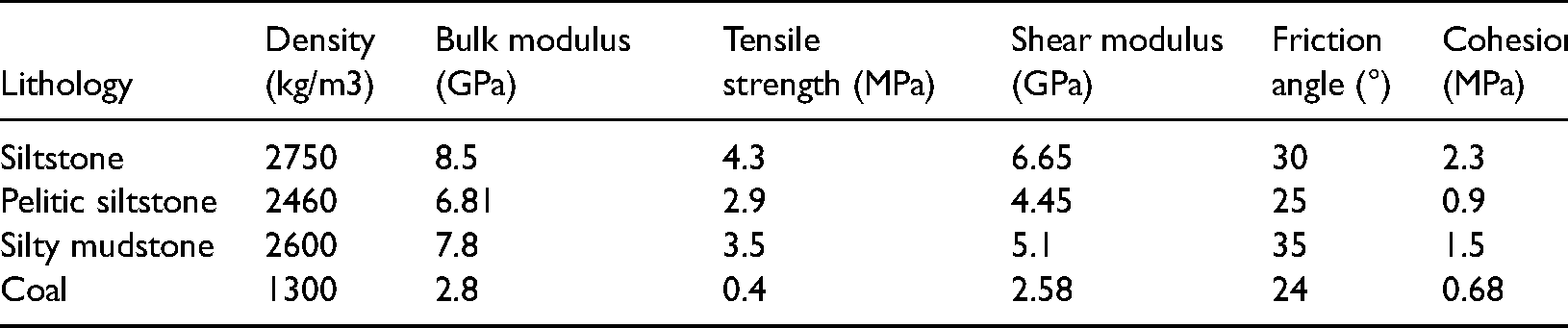
Stress distribution under residual coal pillar
Figure 7 depicts the result of numerical simulation of stress distribution under residual coal pillar. A stress decreased area can be seen at the edge of the residual coal pillar near the gob side. However, a stress-concentrated area appeared under the residual coal pillar, which is more than 40 m under the residual coal pillar. The distance between the C2 coal seam and the C3 coal seam is 13m, which is within the failure area of the floor. Furthermore, according to the actual situation, the deformation of entry under coal pillar is serious, such as frame compression and anchor cable falling off, which conforms to the theoretical calculation results.
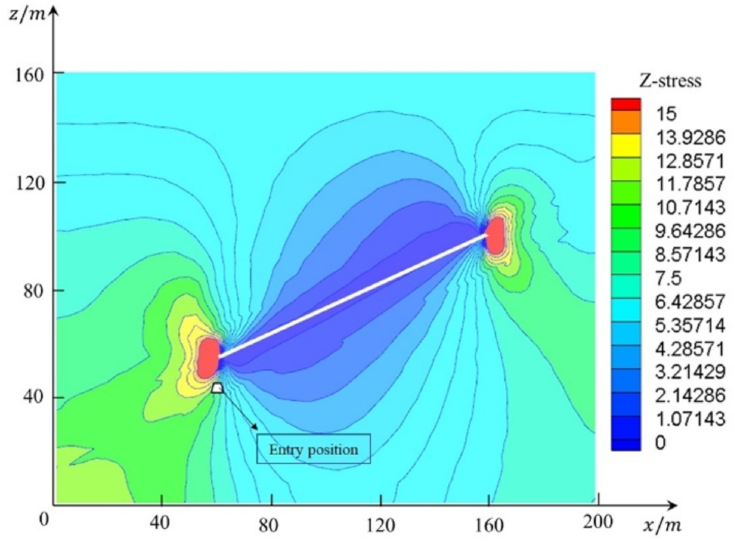
Diagram of stress distribution under coal pillar.
Evolution of stress and displacement of entry roof
Flac3D was used to excavate the range of 50 m ∼250 m of the C3 coal seam in the model shown in Figure 5. Roof pressure and deformation were studied by using two approaches of roof presplitting and non-presplitting. Extracted the vertical stress and displacement value at 0.5 m under the entry, as shown in Figure 8 and Figure 9. Figure 8 (a) shows the roof pressure without roof presplitting, while Figure 8 (b) shows the roof pressure with roof presplitting. It can be seen from the figure that the maximum value of roof pressure without roof presplitting is 13.5 MPa on the coal side and 10.5MPa on the gob side. With roof presplitting, the maximum value of roof pressure on the presplitting side is 12.3MPa, and that on the presplitting side is 9.5MPa. The distribution of stress concentration area and transmission path of stress under coal pillar can be changed by means of roof presplitting. Therefore, the pressure of the entry roof can be significantly reduced to achieve the purpose of pressure relief.
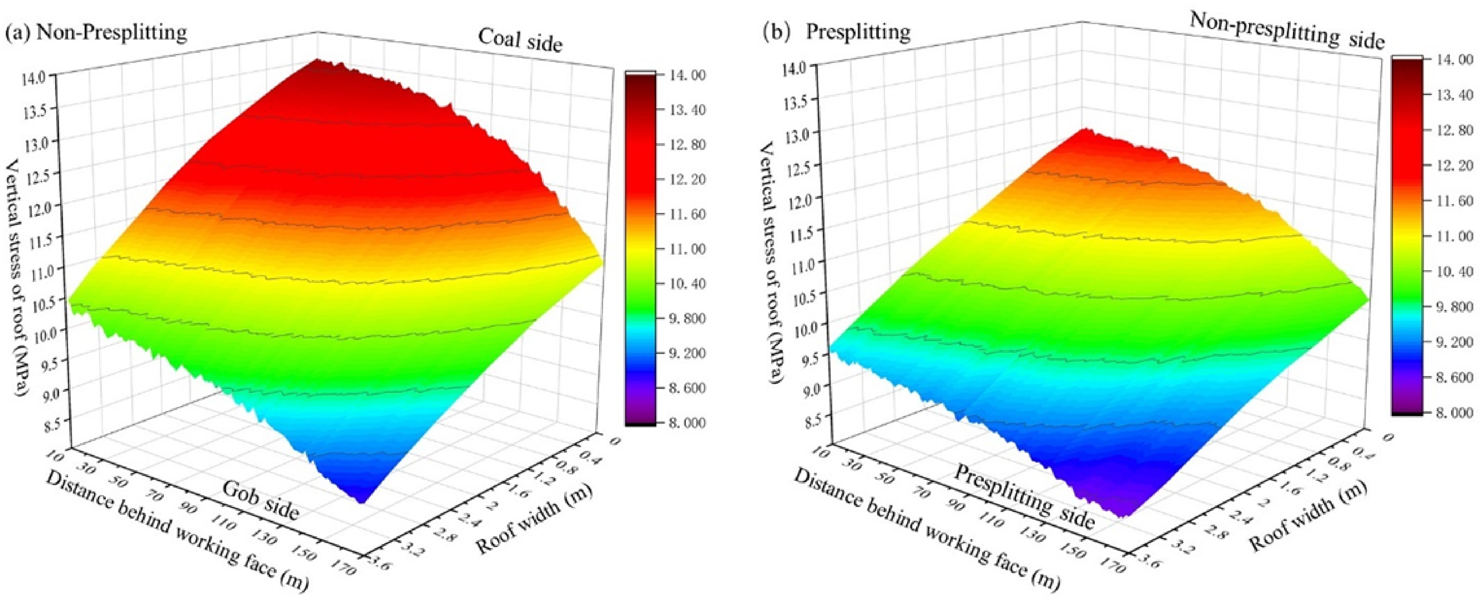
Nephogram of the vertical stress of the entry roof: (a) Non-presplitting; (b) presplitting.
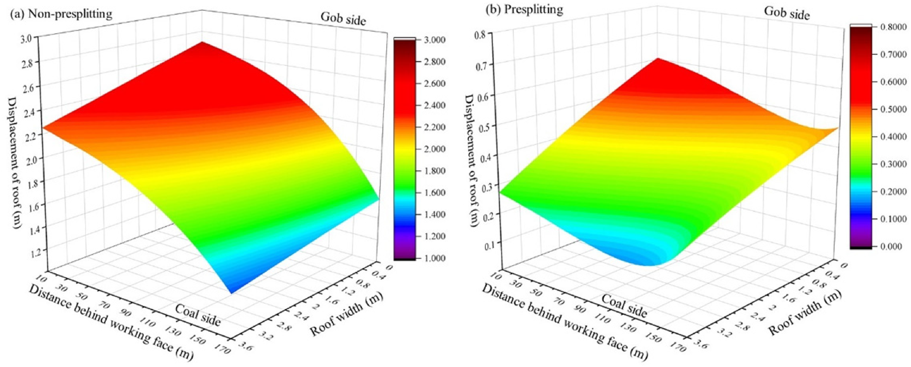
Nephogram of the vertical displacement of entry roof: (a) Non-presplitting; (b) presplitting.
Figure 9 illustrated the numerically simulated displacement of the entry roof with presplitting and non-presplitting. It can be seen that the maximum displacement of the roof without presplitting at the position of gob side behind working face of 10 m is 2.7 m, while the same position in entry roof with presplitting is 0.63 m. The displacement of the entry roof without presplitting is 4.3 times as large as the displacement of the entry roof with presplitting. The decrease of displacement caused by the roof presplitting is attributed to the pressure released.
Key technology of GERRP
Directional Roof Presplit Blasting Technique (DRPB)
The roof presplitting is achieved by means of the directional roof presplit blasting technique (DRPB), which is a method to generate directional cracks between the boreholes in roof rock. Owing to the characteristics of easy deformation under tensile stress, DRPB aims to cut the roof rocks in directional by strong tensile stress generated by blasting. (He, Gao, et al., 2018, Zhang, Chen, et al., 2019, He, Gao, et al., 2017) A point-line energy collecting tube is invented for directional control blasting, As shown in Figure 10. Two rows of energy accumulative grooves, at 180° angles from each other, are designed at the surface of the energy cumulative tube. The outer diameter of the energy cumulative tube is 42 mm, while the inner diameter is 36.5 mm. The diameter of the grooves is 3 mm and the distance of grooves between each other is 5 mm. Then, the energy cumulative tube, which is filled with explosives, is installed in the drill hole. During blasting, due to the small compressibility of the cumulative energy device, the energy is mainly released in the form of kinetic energy, which avoids the energy dispersion caused by the expansion of the explosive gas. Thus, high-energy flow along the set direction and generate concentrated tensile stress, as shown in Figure 10. Hence, under the action of this concentrated tensile tress, the crack propagation along the set direction in the surrounding rock and then forms a pre-cracking surface.
Directional roof presplit blasting device and principles.
Constant Resistance Large Deformation Anchor Cable (CRLDAC)
According to the previous studies, the support structure of entry not only needs a good support performance but also allows a controlled deformation to overcome the large deformation of the entry roof when subjected to the effect of mining activity. (He, Gao, et al., 2017) In this case, the load-carrying capacity of the roof rocks can be fully used to form a stable structure of “support-surrounding rock”. Therefore, an innovation support called constant resistance large deformation anchor cable (CRLDAC), which was invented by (He, Gong, et al., 2014, He, Li, et al., 2017), was utilized in this research. CRLDAC, characterized by a negative Poisson ratio material, is consists of a constant resistance device, steel strand, tray, and locks, as shown in Figure 11. It can reach a constant support resistance of 350 kN and has a capacity of deformation up to1000 mm. (Hu, He, et al., 2019)
Schematic diagram and working principle of CLRDAC.
The working principle of CLRDAC is shown in Figure 11. It can be seen that the end of CLRDAC is anchored in the surrounding rock by the anchoring agent before the deformation of roof rock (stage I). Then, when the coal is mined out at the working face, the dynamic pressure caused by the caving of the gob roof leads to the increase of the deformation of the entry roof, which contributes to the increase of the tensile load of the steel stand. When the deformation of roof rock is lower than the elastic limit of the CRLDAC, little axial deformation occurred to the constant resistance device along with the surrounding rock, as shown in Figure 11 (stage II). In this stage, the tensile stress of the CRLDAC linear increases with the increase of roof rock deformation (He, Li, et al., 2016). The constitutive model of CRLDAC can be defined as:
Owing to the increase of roof deformation, the tensile stress in CRLDAC increased. When the loading stress reach to 
With the working face ongoing, the gob is filled with gangues, which will take the load from the upper rock strata. Hence, under the support of CRLDAC and gangues, the entry roof achieved stability.
Entry retaining design
Design of roof presplitting
The key parameters of directional roof presplit blasting are presplitting angle and presplitting height. The previous researches (He, Gao, et al., 2017, Xue, Gao, et al., 2019) revealed that a reasonable presplitting angle contributes to reducing the deformation of the entry roof. Furthermore, the presplitting height is the key factor to ensure the goaf can be filled with fallen gangues. (Hu, He, et al., 2019) as shown in Figure 12. With a given roof presplitting height, a small presplitting angle
The influence of roof-cutting angle on the roof-cutting effects.
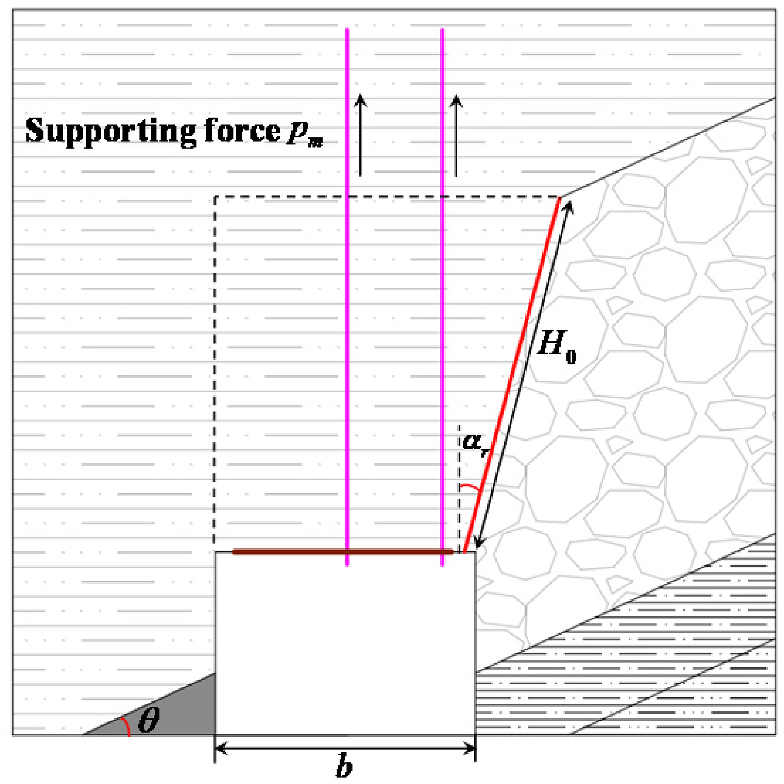
Considering the mechanical properties of roof rock varies from mine to mine, the roof presplitting parameters were designed based on the geological condition of 110301 testing the working face of the Taiping mine. Figure 13 shows the mechanical model of roof presplitting. The presplitting angle, the angle between the presplitting line and vertical line of the roof, is defined as 
Roof prsplitting rock blocks mechanical model.
where T is horizontal thrust,
According to the previous research, T and 
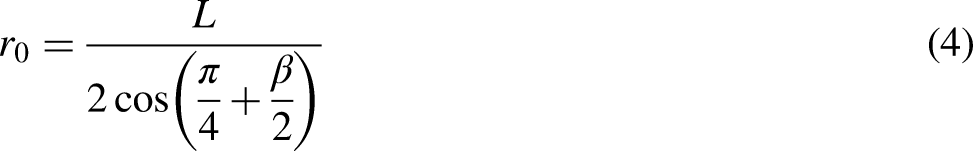
where

Then the presplitting angle can be calculated as:

The presplitting height is calculated as:
Roof presplitting design of entry in 110301 test working face.
Design of entry support
According to the GERRP process, the supporting equipment includes ordinary support (conventional cables), reinforcement support (CRLDAC), temporary support (single hydraulic props), and gangue prevention structures.
In order to make the CRLDAC play a good suspension role in the process of retaining roadway, effectively protect the anchor end, and avoid damage to rock mass within the anchoring range caused by pre-splitting blasting, the length of the CRLDAC is generally designed to be 1∼3m higher than the roof presplitting height (Ma, 2019). The anchor end needs to be located in a relatively stable rock layer.
According to the suspension theory of anchor cable support, the support resistance of CRLDAC should be higher than the weight of rock mass within its support range. The schematic diagram of the support structure of CRLDAC is shown in Figure 15.
Schematic diagram of roof structure supported by constant resistance anchor cable.
The supporting strength of CRLDAC can be determined by the following equation (Zen, 2019):
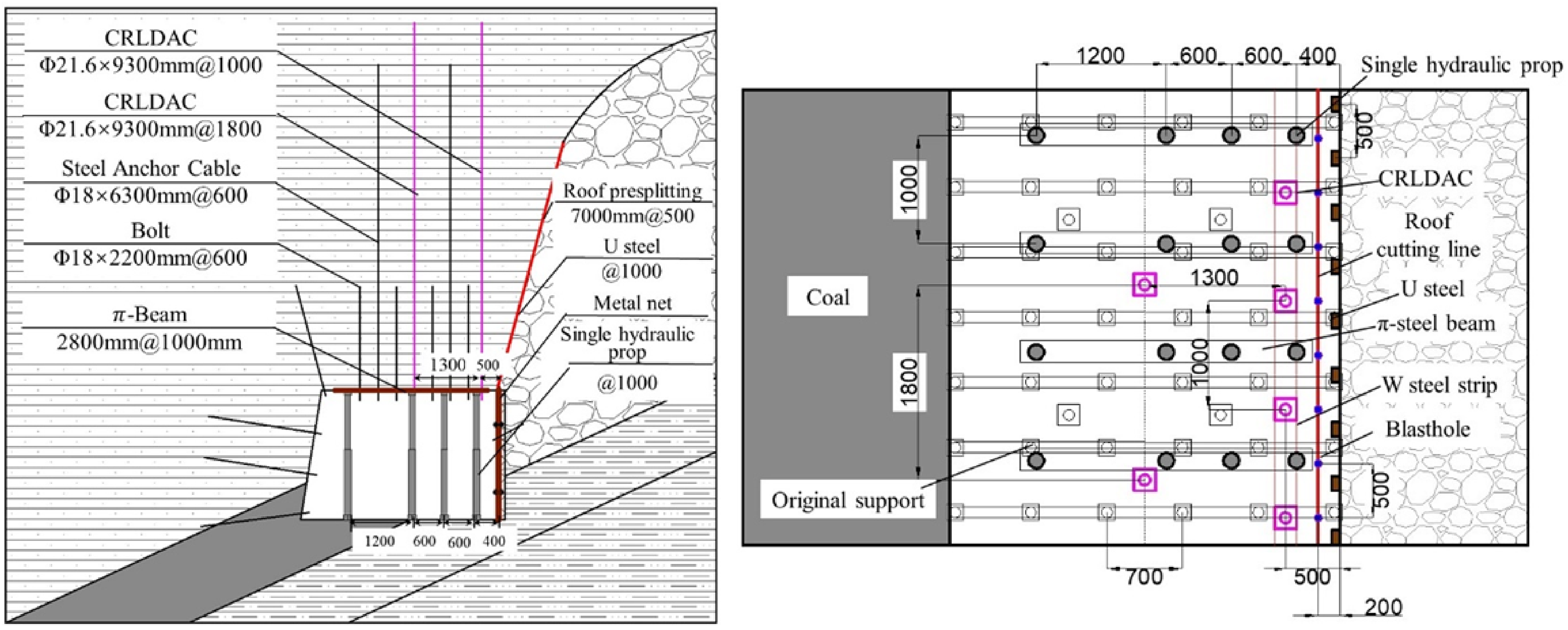
Design of the entry support.
Based on the original support, four ordinary cables (2200 mm in length and 18 mm in diameter), two CRLDACs (9.3 m in length and 21.6 in diameter) were added to the roof of transporting entry of 110301. The single hydraulic props are used as the temporary support structure behind the working face. Four rows of single hydraulic props were installed behind the working face for 200 m. The first row is 400 mm away from the presplitting line, and the other rows are 600 mm, 1200 mm, and 2400 mm respectively away from the first row. The distance between two single hydraulic props in the same row was 1000 mm. The gangue prevention structure was constructed by an extendable U-steel and metal net. As shown in Figure 17, two U-steel, 1.9 in length, were overlapped by two fasteners. The steel net with a mesh size of 80 mm × 80 mm was installed between U-steel and gangues.
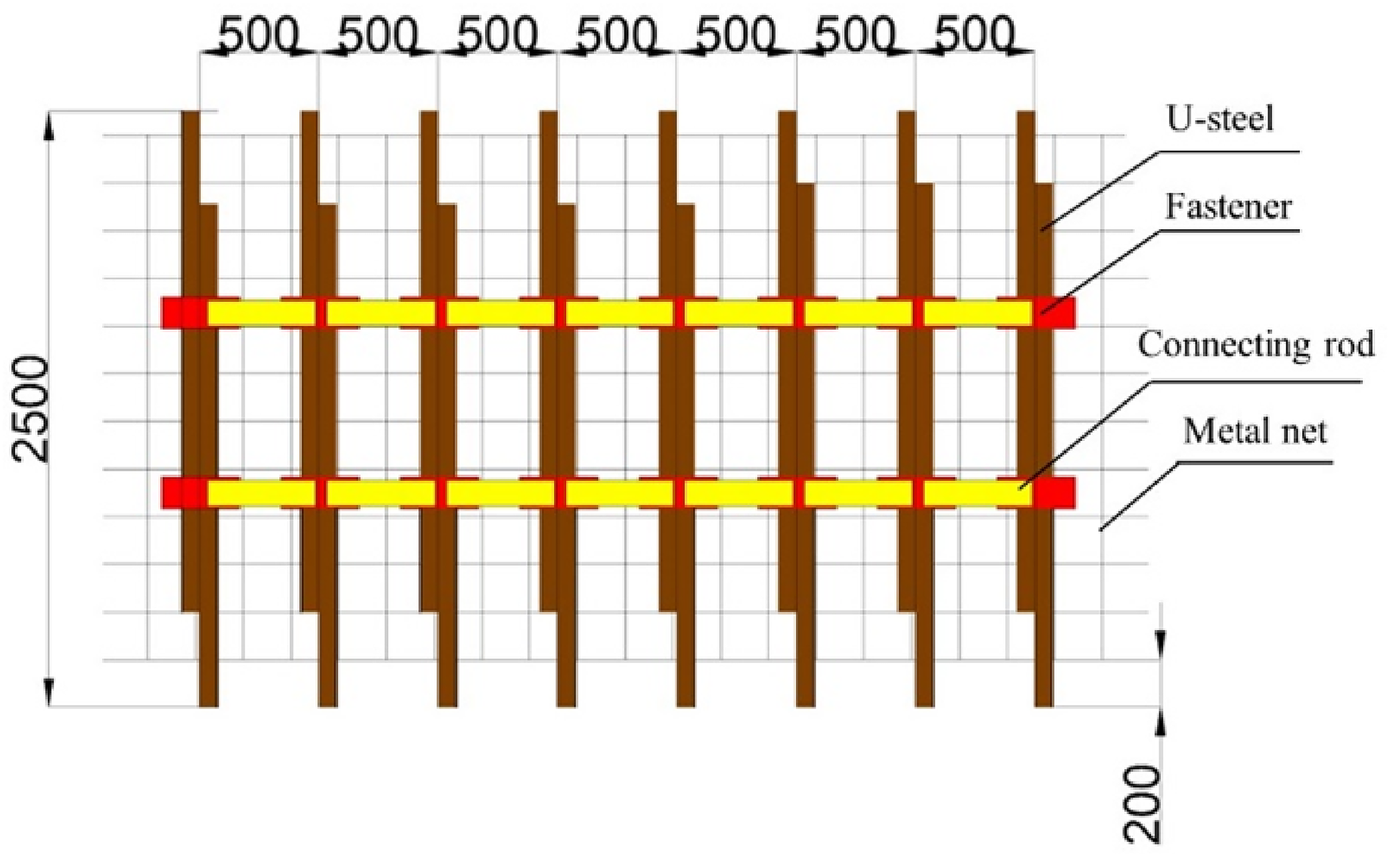
Gangue prevention support structure.
Field test and monitoring
Construction of Key techniques in the field
The CRLDAC construction
Based on the aforementioned designed parameters of entry support. The CRDLAC was constructed as following steps:
Step I: Drill holes according to the designed position with a diameter of 28 mm in the direction of perpendicular to the entry roof. Then, enlarged the holes to a diameter of 75 mm and depth of 9300 mm by using a chambering drill.
Step II: Transporting the anchoring resins to the end of the drilling hole which aims to fix the steel strand to the roof rock. Then, place the steel strand to the end of the drilling hole and stir the anchoring resins for 30 s approximately. When the anchoring consolidated, the steel stand was finally installed.
Step III: Installing the W-type steel band, constant resistance device, cable plate, and cable lock on the steel strand in turn. After the installation of CRLDAC finished, imposed a pre-tightening force of 300 kN at least to the CRLDAC.
Roof presplitting construction
According to the designed parameters, the roof presplitting technique was applied to the 110301-working face in the Taiping mine, the whole process can be divided into four steps:
Step I: Drill the blasting holes 200 mm away from the roof-presplitting side with a depth of 7000 mm and diameter of 500 mm (aforementioned in Section 3). All the blasting holes should be in the same line and at the same angle to ensure the joint-cutting in the same plane within the roof strata (see Figure 10).
Step II: Based on the theoretical and blasting tests, the optimal charging parameters were obtained. Filling the energy collection tube with emulsified explosives with a “3 + 3 + 3 + 2.5 + 2 + 2 + 1” pattern. Meanwhile, the detonators, which were connected by the lead wire, were installed, as shown in Figure 18. Then the front of the energy collection tube was closed by stemming with a length of 2000 mm.
Charging structure and blasting effect of roof presplitting blasting.
Step III: Installed the energy collection tube to the drilling holes. The energy collection grooves must in the same direction.
Step IV: Conducted the blasting according to “coal mine safe construction operation regulations”. After blasting, a cutting line was formed in the designed location of roof strata.
Filed monitoring
Design of monitoring
In order to investigate the effect of residual coal pillar in upper coal seam on the retained entry by means of the GERRP method, the pressure of overlying strata and deformation of surrounding rock were monitored. The arrangement of monitoring equipment is shown in Figure 19. The monitoring stations are arranged every 30 m in the retained entry. In each monitoring station, anchor monitoring apparatus and a single hydraulic prop monitoring apparatus are used to monitor the roof pressure of the retained entry, roof separation monitoring apparatus and convergence monitoring apparatus were used to monitor the deformation of the entry roof. During the process of monitoring, the value of pressure and displacement were obtained as electric signals and then transmitted to a data collection device on the ground.
Schematic diagram of monitoring equipment arrangement. (a): Anchor monitoring apparatus; (b) Single hydraulic prop monitoring apparatus; (c) Deformation of surrounding entry rock; (d) Convergence monitoring apparatus.
Pressure characteristics of retained entry
To study the pressure characteristics of retained entry of 110301 working face, anchor pressure monitor, and single hydraulic prop pressure monitor plot against distances of working face on roof presplitting side as well as non-presplitting side form monitoring station under residual coal pillar was analyzed. Figure 20 shows the variation of single hydraulic pressure. It can be seen that the pressure characteristics on the non-presplitting side and presplitting side have a similar variation trend. The initial value of pressure on the non-presplitting side was 292 kN, while the initial value of pressure on the presplitting side was 285 kN. The non-presplitting side, which was closer to the stress concentration area than the non-presplitting side, had a higher initial pressure due to the heterogeneous stress caused by the residual coal pillar. Along with the advance of working face, the pressure on the roof presplitting side both increased. This is attributed to the effect of dynamic pressure caused by the mining disturbance. Hence, the support structure bore the whole pressure of overlying strata. When the advancing distance of the mining face was 50 m, the pressure increased to the peak value at both sides of the entry. This can be explained by the fractured of the upper main roof. (He, Gao, et al., 2017) Then, the pressure stabilized at a certain level. The gangue caved in the gob compacted and support the roof strata, thus leading to the stability of the entry pressure at the advancing distance of the working face of 120 m(He, Gao, et al., 2017).
Pressure variation low of single hydraulic prop.
Figure 21 illustrated the variety of loading pressure of the anchor cable along with the advancing of the working face. It can be seen that the loading pressure of the anchor cable was significantly affected by the advancing of the working face. When the advancing of the working face was 40 m, the loading pressure of the anchor cable began to increase until reached the first peak value at advancing of the working face is 55 m, and then followed by a slight decrease. This initial increase is attributed to the ruptured of critical strata caused by the disturbance of mining and the followed decrease was due to the energy absorbed by CRLDAC. (He, Guo, et al., 2018) At this period, the roof strata on goaf caved which leads to the continued growth of loading pressure of anchor cable. When the energy absorbed beyond the maximum value of CRLDAC, the monitored value again increased to the second peak value at the advancing of the working face was 100 m. Finally, with the gangue filled the gob, the loading pressure of the anchor cable stable at a value of 38 kN at gangue rib side and 34 kN at coal rib side behind the working face of 120 m. It also can be seen from Figure 21 that the loading pressure of the anchor cable on the gangue rib side was larger than that on the coal rib side.
Loading pressure variation low of anchor cable.
Entry deformation monitoring
In the field test, with the application of the GERRP method, the deformation of the entry roof was well controlled. To investigate the stability of the entry roof under the GERRP approach, the vertical deformation (roof to floor convergence) as well as the horizontal displacement (coal rib to gangue rib convergence) of retained entry, were analyzed, as shown in Figure 22 a and b. It can be seen from these figures that the deformation of surrounding entry rock increased with the advance of working face until stable at advancing distance of working face of 160 m. The vertical displacement of the entry roof was stabled at 511 mm, while the horizontal displacement of the entry floor was stabled at 421 mm. The final roof deformation was 312 mm, and floor deformation was 199 mm, while the displacement of gangue rib was 251 mm, the displacement of coal rib was 170 mm. Figure 22 c and d illustrated the convergence rate of the roof, floor, gangue rib, and coal rib of retained entry. As can be seen, the whole deformation process of surrounding entry rock can be divided into four stages. The sink ratio of the entry roof and the heave ratio of the floor were less than 2 mm/d before 30 m distance behind the working face (stage I). However, during 30 to 110 m distance behind the working face (stage II), the roof sinking rate, floor heave rate, and convergence rate of gangue rib and coal rib increased quickly. The roof sinking rate can be up to 17 mm/d while the floor heave ratio is up to 10 mm/d. This increase of roof sinking ratio and floor heave ratio at 30 m to 110 m behind the working face was attributed to the cave of immediate roof caused by disturbance of working face. (He, Guo, et al., 2018) From 110 m to 160 m behind the working face, the convergence rate of both roof and floor decreased (stage III). In this stage, the CRLDAC and single hydraulic prop bore the whole pressure from the overlying strata to prevent the roof from deformation. After 160 m behind the working face, the convergence rate of roof and floor decreased close to 0 mm/d and the surrounding entry rock reached stable (stage IV). In this stage, the roof rock caved and filled the gob, which supported the overlying strata. These results corresponded to the analysis of pressure characteristics of the entry roof in section 4.2.2. In addition, the convergence rate of gangue rib presents a similar trend to the convergence rate of roof and floor. However, the deformation of coal rib was later than the deformation of gangue rib (see in Figure 22 d). This can be explained by the fact that the coal rib was more stable than the gangue rib when subjected to the disturbance of the working face. (He, Gao, et al., 2017)
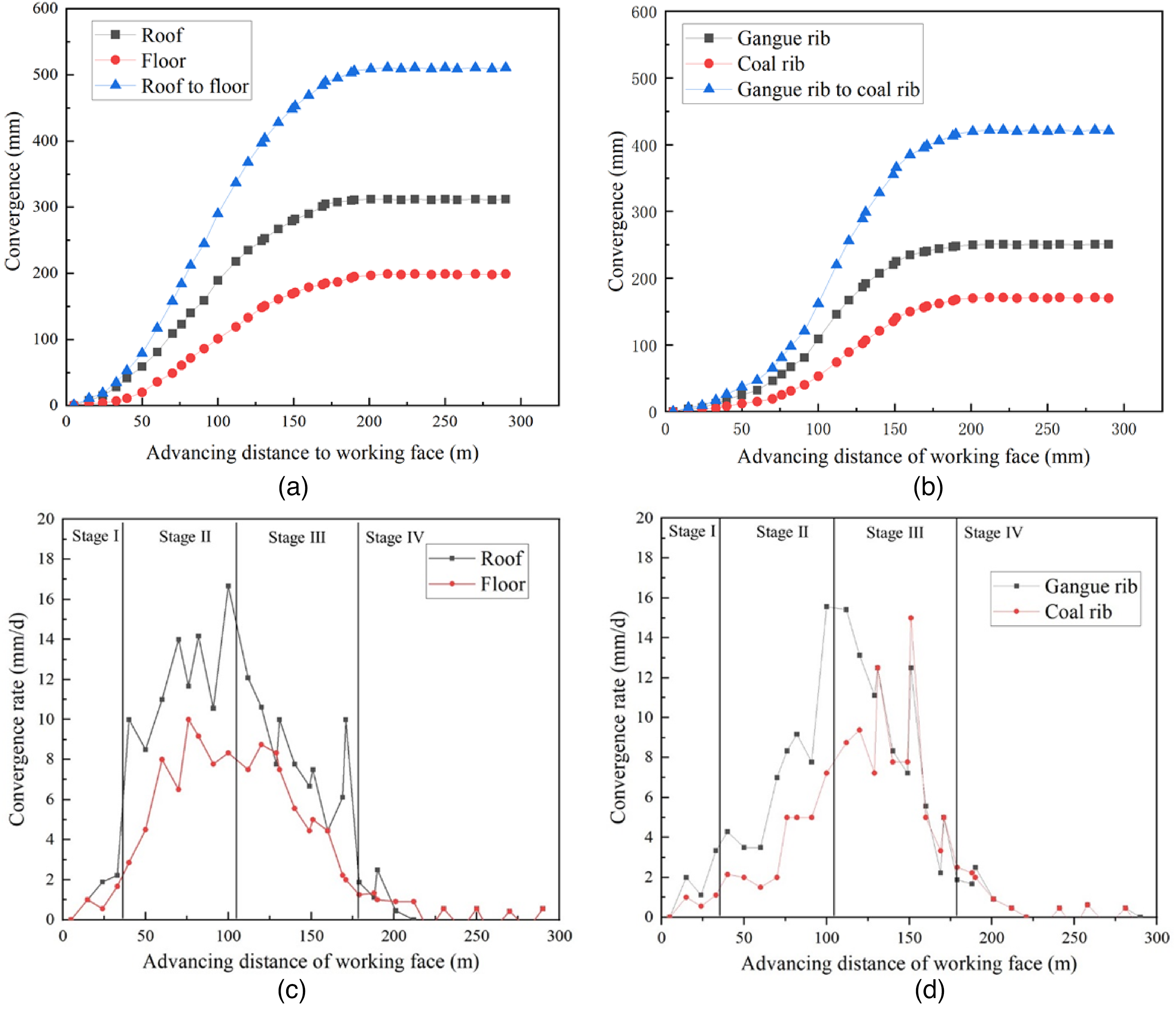
Convergence and convergence rate of surrounding entry rock.
According to the above discussion, the final deformation of stabled retained entry was 511 mm in vertical and 421 mm in horizontal. Figure 23 shows the retained entry after the GERRP application in the 110301 working face in the Taiping mine. The retained entry was sufficiently met the requirements as the air return roadway for the next working face.
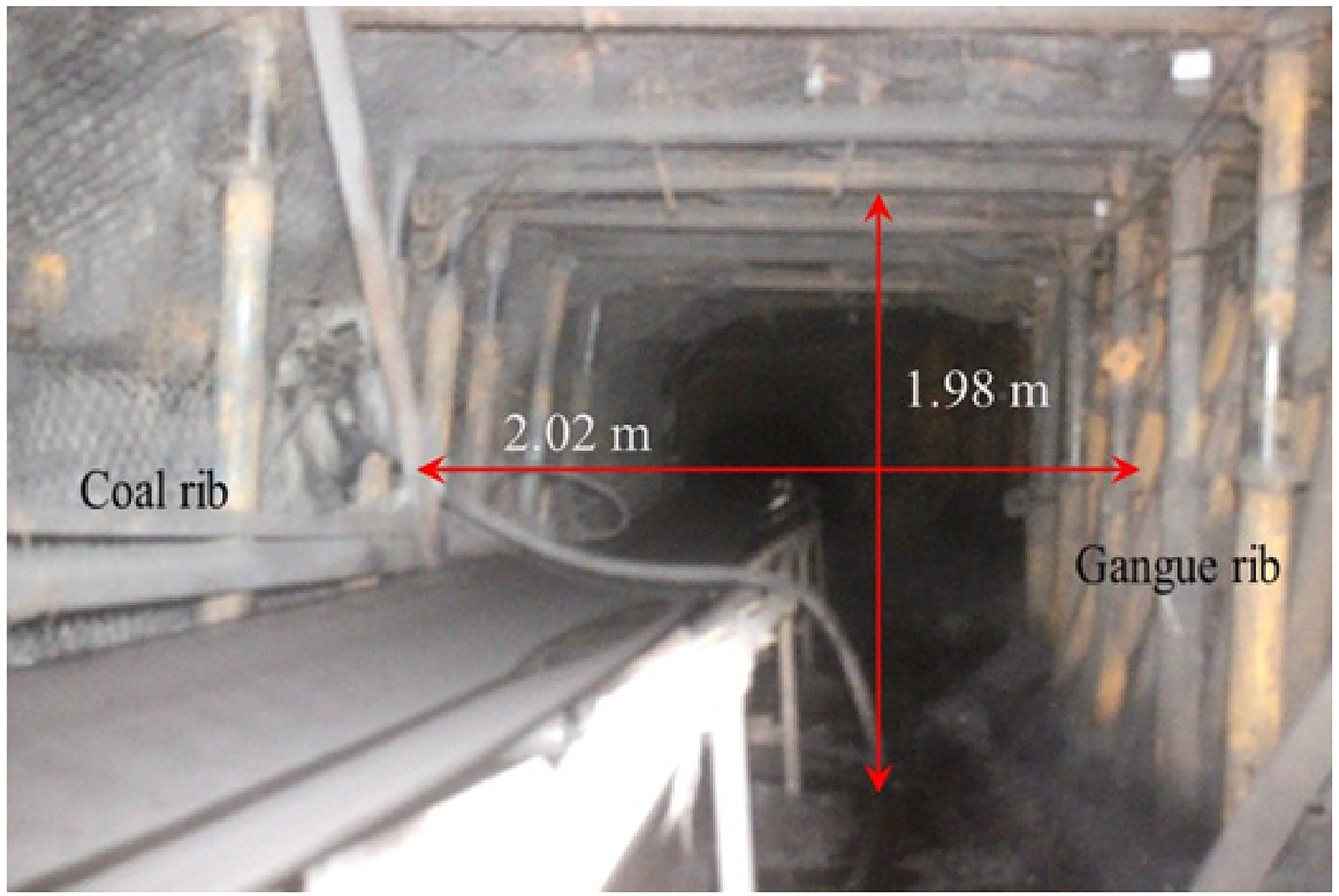
Overall effect of the retained entry utilizing the GERRP method.
Furthermore, the economic benefits of 110301 working face also increased obviously due to the utilizing GERRP technology. Compared to the conventional longwall mining method, GERRP eliminates one entry-excavation and remained coal pillar. According to the economic statistics of Taiping Mine, the cost of entry excavation is 7000 RMB/m. The length of the entry is 540 m, Therefore, GERRP decreased the input cost of 3780000 RMB. Meanwhile, the coal pillar, which weighs up to 24300 t, can be recycled. GERRP is also attributed to the improvement of production efficiency due to the simplification of the production process.
Summary and conclusions
In this study, an innovative mining method, gob-side entry retention by roof presplitting (GERRP), was applied to the lower coal seam mining under the residual coal pillar. The principles and the whole processes of GERRP were proposed. Two key technology, directional roof presplit blasting technique (DRPB) and constant resistance large deformation anchor cable (CRLDAC) were further introduced. The stability of retained entry was studied by means of numerical simulating and field tests. The following conclusion can be obtained:
Key parameters, roof presplitting height, and roof presplitting angle of DRPB, were designed based on the theoretical analysis. The reasonable roof presplitting height was 7 m and the roof presplitting angle was 15°. The support structure of retained entry also was designed. The length of CRLDAC was determined to be 9.3 m.
The stress distribution of the entry roof under the residual coal pillar was studied based on theoretical analysis and numerical simulating. The results show that the depth of stress concentration area is more than 44 m. With the application of GERRP, the vertical stress and displacement of the entry roof were decreased compared to the conventional method.
In the field test, the pressure of retained entry roof, as well as the deformation of surrounding entry rock, were monitored. Field monitoring showed that the variation of pressure of retained entry roof was significantly correlated to the deformation of surrounding roof rock. From 0–30 m behind the working face, the pressure and deformation of the entry roof both increase at a low rate. However, from 30–110 m behind the working face, the pressure of the entry roof increases quickly thus leading to large deformation of the entry roof. From 110–160 m, the increased rate of entry roof pressure, as well as the deformation of surrounding entry rock gradually slowed down and then stabled at 160 m behind the working face. The maximum convergence of roof to the floor was 511 mm, and gangue rib to coal rib was 421 mm.
This study provided an innovative method that applied to the multi-seam coal mine. According to the results of numerical simulating and field tests, GERRP is an effective way to solve the large deformation of the entry roof under the residual coal pillar. The retained entry met the requirement of the next working face and confirmed that the use of GERRP in the multi-seam coal mine, which has the residual coal pillar in the upper coal seam, was feasible, effective, and economical.
It is noted that the model in this paper was successfully tested in a close coal seam mine. However, future work is still needed to investigate the mechanism of the effect of roof presplitting on the overlying strata as well as the coal rib. Meanwhile, the mechanical property of the gangue support structure is also vital to the effect of retained entry. Furthermore, the impact of distance between coal seams is also a vital factor that needs to be investigated. Hence, the application of GERRP technology can be broadened to more coal seams with different mechanical characteristics.
Footnotes
Acknowledgment
This study is supported by the State Key Research Development Program of China (No. 2016YFC0600900) and the National Natural Science Foundation of China (No. 51574248), which are gratefully acknowledged.
Declaration of conflicting interests
The author(s) declared no potential conflicts of interest with respect to the research, authorship, and/or publication of this article.
Funding
The author(s) disclosed receipt of the following financial support for the research, authorship, and/or publication of this article: This work was supported by the State Key Research Development Program of China, National Natural Science Foundation of China, (grant number No. 2016YFC0600900, No. 51574248).