
Abstract
After mining the upper-goaf side, large coal pillars and part of hard roof exposed above the pillars remain. The hard roof can significantly deform the roadway by transferring high stress through coal pillars to the roadway. This paper reports the use of hydraulic fracturing technology to cut the hard roof on both sides (i.e. the broken roof slides to the goaf) to relieve the pressure. The position of the roof fracture is the key to controlling the pressure relief. The bearing characteristics of the large coal pillars and hard roof are analyzed to establish a mechanical model of the broken-roof sliding instability after directional fracturing and determine the width of the coal pillars that can collapse under maximum overburden load on coal pillars as a reasonable hydraulic fracturing position. The results show that the distance from the mine gateway to the fracture location increases with increasing hard-roof length, coal pillar depth, coal pillar thickness (mining height), and goaf width. In addition, the distance to the mine gateway decreases with increasing coal strength, support of the coal pillar by the anchor rod, cohesive force, and internal friction angle of the coal–rock interface. Engineering tests were applied in coal roadway 5107 of coal seam 5# of the Baidong Coal Mine of the Datong Coal Mine Group. Given the site conditions, a reasonable fracturing length of 8.8 m was obtained. Next, directional hydraulic fracturing was implemented. The comparison of the roof deformation before and after fracturing suggests that this method reduces the local stress concentration in coal pillars, which allows the surrounding rock deformation in roadway 5107 to be controlled.
Introduction
The mining of close coal seams with a hard roof is widespread in the Datong and Jincheng mining areas in China. The large upper-goaf-side coal pillars of close coal seams concentrate stress in the lower mining space, while the hard roof above the coal pillars further increases the stress concentrated by the coal pillars. Because of the superposition of dynamic and static loads in the mining space below the coal pillars, the concentrated stress can easily cause phenomena involving strong underground pressure, such as large deformations of the mine floor and mine gateway or rock burst (Dou et al., 2015; Jiang et al., 2014; Qi et al., 2013), which seriously hinders the safety and production of the mine. Directional hydraulic fracturing technology can form artificial fracture lines in the hard roof, which can break the roof in the given direction. Field practice shows that controlling the fracture line is very important for hydraulic fracturing of a hard roof and that the position of the fracture line directly affects roof fracturing and stress redistribution. Therefore, a good understanding of how to relieve high local stress below the coal pillar by positioning the roof fracture line is vital to transfer the roof load to the goaf.
Systemic research into how to break hard roofs in multi-seam coal mining (Yang et al., 2014; Yu et al., 2013; Yu 2015) mainly considers the impact of fractured stope and the instability and control of roof breaking and its impact on mining the lower coal seam. Combined with microseismic monitoring data, this research found that the breaking of the hard roof can induce the sudden release of energy accumulated in the coal pillar area, causing the rock to burst in the working face. The hypocenter is typically located in the coal-pillar side of the goaf, especially in the space of hard-roof compression and rebound after its fracture (Zhao et al., 2012). Compared with traditional blasting technology (Banerjee et al., 2003; Sawmliana and Roy, 2012), hydraulic fracturing has the advantages of a large range of control of a single hole, small dynamic disturbance, long working distance, and the ability to be safely used in high gas mines (Huang et al., 2013). Coal-seam hydraulic-fracturing technology can increase the number of cracks, relieve pressure, improve the permeability of coal seams, and displace gas in coal seams (Yue et al., 2019a, 2019b). Hydraulic cutting can control the direction of hydraulic cracks (Xu et al., 2011; Yan et al., 2015), whereas deep-hole hydraulic-controlled blasting (Ye et al., 2017) and high-pressure pulsating hydraulic fracturing (Li et al., 2014; Lin et al., 2011; Zhai et al., 2012) increase the number of cracks and improve the pressure relief in coal seams. Directional hydraulic fracturing weakens hard roof (Lin et al., 2016), prevents rock burst (Dou et al., 2012; He et al., 2012), prevents the first collapse of hard roof to form hurricane, reduces the advance support pressure of the working face (Kang and Feng, 2012), and controls the deformation of coal pillars under hard roof (Wu et al., 2017). Cutting off the roof between the goaf and the roadway to realize pressure relief for retained roadway (He et al., 2018; Sun et al., 2014). Yu et al. (2014) hydraulically fractured the hard roof of an extra-thick coal seam in the Datong Mining Area and transferred the high stress to the roadway (Yu and Duan, 2014). Huang et al. (2018) analyzed the reasonable breaking position of hydraulic fracturing in hard overhanging roof of a goaf roadway.
To date, few studies have investigated how to relieve high local stress that occurs during directional hydraulic fracturing of the hard roof of large goaf-side coal pillars. In addition, there is a poor understanding of the methods used to determine the position of directional fracturing, and the patterns of roof movement and stress distribution before and after fracturing are not clear. As a result, there is no theoretical basis to guide the implementation of directional hydraulic fracturing of the hard roof of large goaf-side coal pillars. To address this issue, a case study is used of the large deformation of gateway 5107 in coal seam #5 of Baidong coal mine of Datong Coal Mine Group to analyze the principle behind the high stress in the hard roof above the large upper-goaf-side coal pillars and thereby determine the mechanical mechanism that underlies the directional hydraulic fracturing of hard roof and determine how to position the room fracturing line to effectively prevent the accumulation of significant underground pressure in gateway 5107 of coal seam #5.
Loading characteristics of large coal pillars in goaf under a hard roof
Occurrence
The Baidong Coal Mine of Datong Coal Mine Group is located in Datong City, Shanxi Province (Figure 1(a)), with the mining currently focusing on coal seams 3# and 5#. Figure 1(b) shows the plane layout of the working face. The mining of coal seam 3# was completed in 2002–2004, so working faces 8105 and 8107 in coal seam 3# are goaf with a 30 m residue of coal pillar. The current mining activity is focusing on working face 8107 of the lower part of coal seam 5#, which is at an elevation of 945 m, a ground elevation of 1395 m, an average burial depth of about 450 m, a length of 1927 m, and a 135-m-long slope. Figure 1(c) shows the pillar shape of working face 8107 in coal seam 5#. The average thickness of the overlying coal in coal seam 3# is 4.1 m, whereas the average thickness of the lower part of coal seam 5# is 11.2 m. In addition, coal seams 3# and 5# are 5.1 m apart and belong to the close coal seams. The interlayer rock mainly consists of mudstone with bedding development and one to two layers of coal lines. Note that 2.48 m of mudstone and 8.81 m of an old hard roof formed with sandstone are above the large coal pillars in the goaf. In addition, the coal pillars in both the upper and lower coal seams are arranged in an overlapping manner, ranging from 630 m in front of the cutting hold to the stop line. The coal pillars are all 35 m wide. The mechanical parameters of each rock layer are given in Table 1.
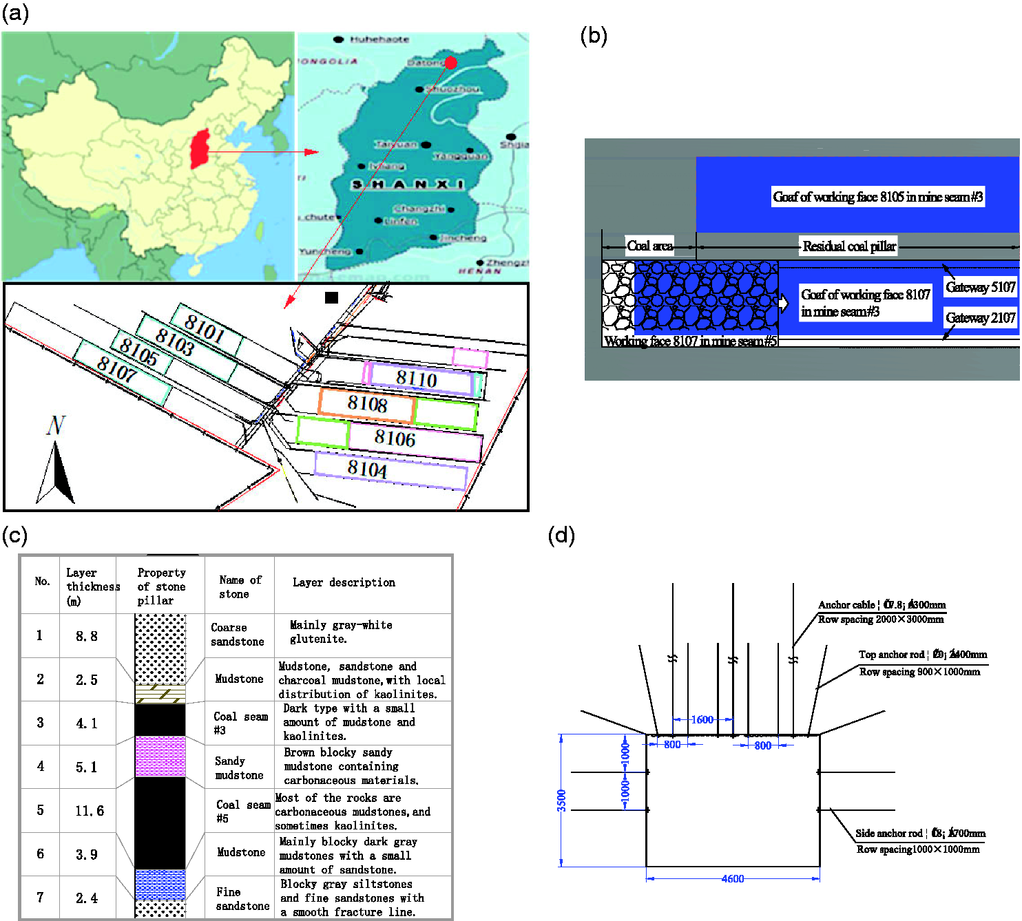
Geological conditions and layout of working face: (a) geographic location; (b) work surface layout; (c) pillar plot of the working face; (d) cross section and support of gateway 5107 of coal seam #5.
Mechanical parameters of major coal seams.
Gateway 5107 of coal seam 5# has a rectangular cross section and is used for material conveying and air return of the working face (Figure 1(d)). The gateway width × height = 4.6 × 3.5 m and the net cross-sectional area are 16.1 m2. The gateway is supported by anchor rods, anchor cables, and metal meshes. For the coal area, the row spacing between top anchor rods is 800 × 100 mm; the top anchor cables are arranged along the gateway with a 3–0–3 arrangement, and their row spacing is 1600 × 1300 mm. The site walls of the gateway are supported by three anchor rods with a row spacing of 1000 × 120 mm.
Bearing characteristics
The hard roof is characterized by large thickness, high strength, and good overall performance. After the working face is mined, the hard roof will hang at a continuous plate without breaking. When the working faces at both sides are mined, the roof on top of both sides of the coal pillar becomes suspended for several meters to several tens of meters beyond the edge of the coal pillar, and the roof area can reach tens of thousands of square meters. Large coal pillars tend to have a high bearing performance and stability and can remain stable in the goaf for decades without failure due to instability.
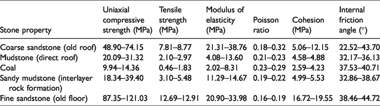
Figure 2 shows the bearing characteristics of the large coal pillars in the goaf under the hard roof. After mining the working faces 8105 and 8107 in the upper 3# coal seam, the hard roof is suspended without breaking and is not connected with the floor slab of the goaf. The load on the rock above the goaf is transmitted to the hard roof, which carries a large load and accumulates a significant amount of elastic energy. The hard roof above the coal pillar is structured like a cantilever beam, and the additional load it generates places a strong eccentric load on the large coal pillar (i.e. a large compressive stress on the outer coal pillar and a small compressive stress on the inner coal pillar), so that high peak stress and deviatoric stress form across the width of the coal pillar, which exacerbates the deformation of the coal pillar. The coal pillar thus transmits a huge load to the bottom plate and continuously compresses the bottom plate of the coal pillar, resulting in a high concentration of stress on the bottom plate, which increases the deviatoric stress in the bottom plate (Bai et al., 2012; He et al., 2014; Wen et al., 2009; Xu et al., 2015), leading to a die-pressing effect and the overall shear destruction of the rock formation on the bottom plate (Wang et al., 2012), which transitions into a plastic-flow state. When working faces 8107 and 8105 in the lower 5# coal seam are mined again, the high stress and mining stress transmitted from above are superimposed to aggravate the deformation of gateway 5107 in the 5# coal seam, thus causing strong underground pressure such as floor lift. In addition, the overlapping arrangement of the remaining coal pillars in the upper and lower coal seams poses a hidden risk of instability of the coal-pillar groups under long-term rheological action.
Bearing characteristics of large coal pillars under suspended hard roof: (a) sinking roof; (b) floor lift: (a) floor plan; (b) A–A crosssection.
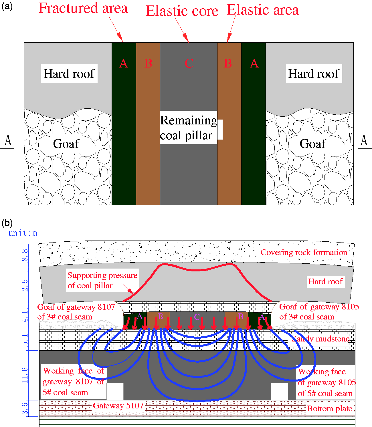
Figure 3 shows the result of strong underground pressure in gateway 5107 of 5# coal seam. The advanced-abutment pressure of the working face had a 40 m range of impact, the maximum sinking distance of gateway 5107 was 1.2 m, and the side-lift length on the gateway wall was 0.4–0.6 m. Some of the top anchor rods and anchor cables failed, and some of the steel belts fractured. In response, the advanced-abutment section was extended to 160 m by using a single support, and the number of rows of support pillars was increased from three to four with the row spacing reduced from 1.2 to 1.0 m. In addition, raft support was also added for protection, with 40 m separating the rafts. After implementation, the deformation of the gateway remained apparent, and the gateway height was reduced to 2.4–2.8 m. The height of the gateway was less than the minimum height of the transitional bracket of 2.5 m, so the stroke of the bracket column was less than 0.8 m, and a manual bottoming operation was required for each shift. The large amount of work required significantly affects the safety and mining efficiency of the working face.
Result of strong underground pressure at gateway 5107 in 5# coal seam: (a) sinking roof; (b) floor lift.
Principle for determining the location of double-sided directional fracture for pressure relief of hard roof of large upper-goaf-side coal pillars
The hard roof carries a huge load transmitted from the upper rock formation and transmits the load to the coal pillar itself, thus concentrating stress on the floor plate of the coal pillar and transmitting the high stress from the hard roof to the coal pillar to the floor. To relieve the pressure from the double-sided directional fracturing of the hard roof of large upper-goaf-side coal pillars, one proposed method is to break the roof and allow it to slowly rotate and slide down to the goaf. The layer of rock covering the roof also falls to the goaf, so that the load applied to the coal pillar is removed to a certain extent and transferred to the goaf. In this way, the load-bearing structure is optimized, and the overall stress environment tends to become more uniform.
Figure 4(a) depicts the method of double-sided directional fracturing of the hard roof of large goaf-side coal pillars. Two boreholes (called A and B) were drilled through the hard roof above the coal pillars via the floor plate of transport gateway 5107. Borehole A was not pre-processed but was directly used for fracturing. A pre-cut annular groove was generated at the bottom of borehole B by using a slotting drill bit to increase the stress concentration around the annular groove and thereby generate directional fracturing. Because the fractured regions were all located inside regions with concentrated tensile stress, both boreholes generated a vertical roof fracture line. When the position of the fracture in the hard roof was at the outer side of the coal pillar (Figure 4(b)), i.e. the fracture position was outside the coal pillar, the roof rock layer overhanging the goaf-side coal pillar would produce a curved separation layer and facilitate the infiltration and spilling of high-pressure water along the cracks in the separation layer, causing the roof to stratify and fall. Therefore, it would be difficult to form vertical cracks and cut the hard roof as a whole. The overhang of the hard roof above the coal pillar would still remain after fracturing.
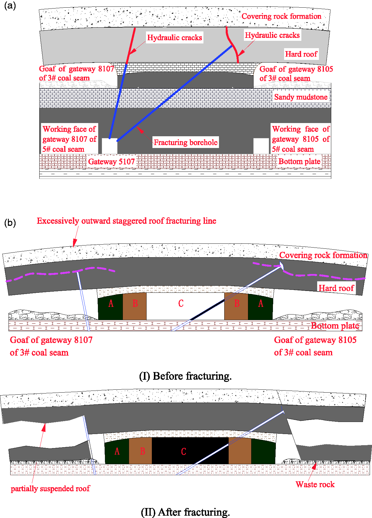
Reasonable directional fracturing position of hard roof of large upper-goaf-side coal pillars: (a) schematic diagram of directional fracturing of hard roof of large upper-goaf-side coal pillars. (I) Before fracturing. (II) After fracturing; (b) outward staggered roof fracturing line. (I) Before fracturing. (II) After fracturing; (c) properly inward staggered roof fracturing line. (I) Before fracturing. (II) After fracturing; (d) excessively inward staggered roof fracturing line.
In addition, because the roof rock layer suspended above the outside edge of coal pillar above the goaf would produce a curved abscission layer, the high-pressure water could easily seep along the crack on the abscission layer, making vertical fracture cracks difficult to form and rendering the effect of roof fracturing was difficult to predict. As the fracturing position moves toward the coal pillar, the broken roof would gradually move toward the edge of the coal pillar (Figure 4(c)). In this way, the relieved load from the covering rock layer by the fracturing of roof would gradually increase, as would the width of the coal pillar damaged by the slip and fall of the suspended roof, thus reducing the effective width of the remaining coal pillar. When the coal pillar below the hard roof reached a suitable width, the fractured roof would rotate gently under the support of the coal pillar below it, and then the entire roof would slide down to the goaf and crush the coal pillars in the fractured and plastic zones below. In addition, the fractured roof would be in contact with the coal seams in the goaf. At the same time, the soft rock layers above the fractured roof would also fall and further fill in the goaf to form a stable bearing body, which not only would share the load of the coal pillar, but would also crush a part of the coal pillar, thus reducing the effective length of the coal pillar and decreasing the overall bearing capacity.
From the perspective of the expansion of hydraulic cracks, after the roof fracturing was properly moved toward the coal pillar, the curvature of the roof and its lateral tensile force at this position both increased, which in turn helped generate vertical cracks and increase roof fracturing. When the roof fracturing avoided the curved abscission layer of the roof in the goaf, the high-pressure water could not enter the layer crack, ensuring the fracturing. Of course, the distance moved by the roof fracture toward the coal pillar should not be too large (Figure 4(d)); otherwise, the fractured roof would touch the waste rock at one side while its other side would remain pressed on the coal pillar. The stress in the coal pillar would remain high, and stress would be difficult to transfer.
During the directional fracturing of the hard roof of the large upper-goaf-side coal pillars, a reasonable position of roof fracturing should be known so that the original overburden load of the coal pillar could be transferred to the goaf to the maximum extent. Therefore, only once, the overburden load Q of the coal pillar exceeded the total load FN that could be withstood by the coal pillar would the fractured hard roof slide down and crush some of the coal pillars below.
Determination of fracturing position for double-sided directional fracturing of hard roof of large upper-goaf-side coal pillars
Mechanical model
Figure 5(a) shows a three-dimensional force model of the double-sided directional fracturing of the hard roof of the large upper-goaf-side coal pillars, which simplifies the situation to a plane-strain problem. The mechanical model describes the width direction of the coal pillars, as shown in Figure 5(b). Because the geometry of the problem is symmetric about the center of the coal pillar, half of the coal pillar suffices as research object. The overburden weight of the covering rock layer acts on the hard roof in the form of a uniform load, and a shear stress
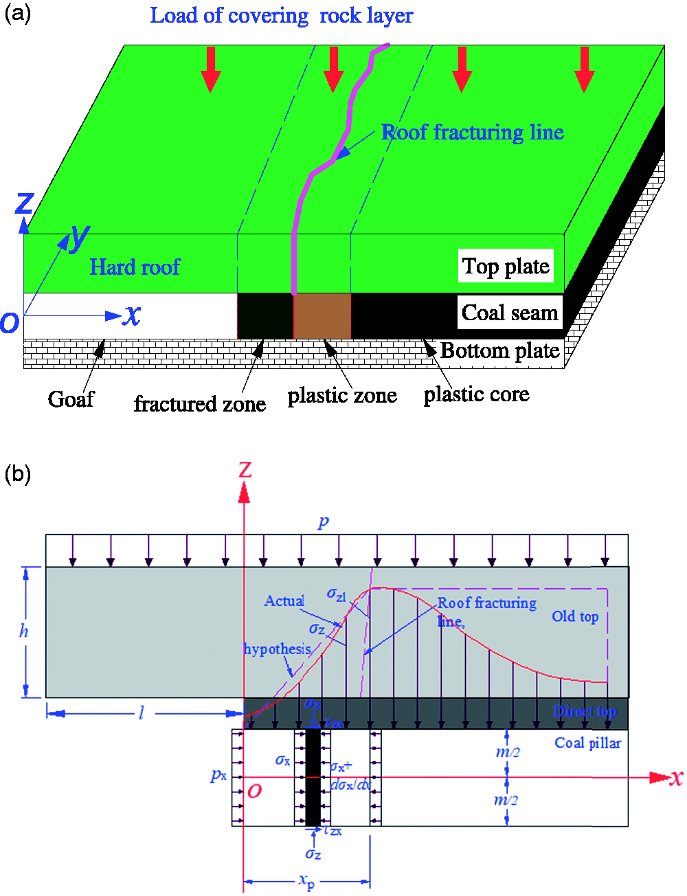
Mechanical model of directional fracturing of hard roof of coal pillar: (a) three-dimensional force model; (b) plane mechanics model.
In the model, H is the depth of the coal pillar (m), m is the height of the coal pillar (m), B is the width of the coal pillar (m), D is the length of the goaf (m), l and h are the length (m) and thickness (m) of the suspended old roof, E is the elastic modulus of the old roof (GPa),
Model resolution
Basic assumptions (Hou et al., 2015; Wu and Wang, 1995; Zhang et al., 2016)
Both the coal seam and the hard roof are assumed to be uniform, continuous, isotropic ideal elastic–plastic materials. The side yielding zone of the coal body is in a critical elastic state, and the coal body in the yielding zone maybe treated as a linear elastomer. The deflection of the roof is neglected, and the load on the hard roof is uniform.
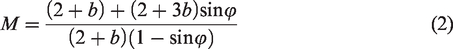
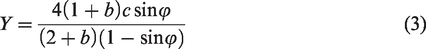
Ultimate strength of coal pillars
Based on the unified strength theory 
Yield width of coal pillars
As shown in Figure 5, the coal–rock interface should satisfy the following differential stress-balance equation

The shear stress at the coal–rock interface must satisfy


Based on the solution for the yielding width of the coal pillar in the gateway (Wu and Wang, 1995), the yield width of the coal pillar under the hard roof 
Actual load on coal pillar
Figure 6 shows the actual load on the coal pillar. In addition to the complete collapse of a part of the rock formation above the goaf, another part of the rock formation was supported by as hinged beams. The fallen rock would fill the goaf. Once the waste rock reached the top of the goaf, it would share the weight G of the part of the covering rock formation. The rest of the load P would be transmitted to the surrounding coal pillars through the hinged rock layer (i.e. the waste rock and coal pillars in the goaf would together support the load P + G of the overburden rock).
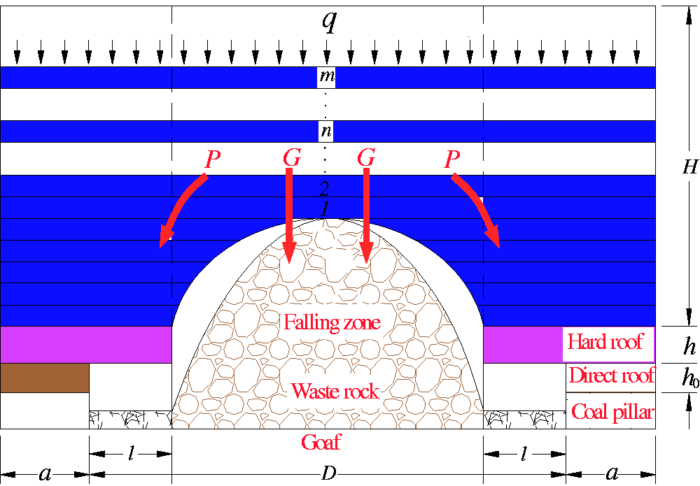
Actual load of coal pillar.
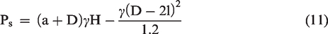
The Baidong coal mine has a depth H = 450 m (0.3 H = 0.3 × 450 = 135 m). When the mining width b = 135 m, b = 0.3H. According to Wilson’s theory, the hard roof actually bears the following load of the overburden rock before fracturing
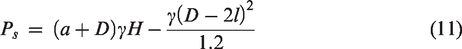
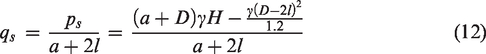
Before fracturing, the uniformly distributed load of the hard roof subjected to the overburden rock was
Determination of reasonable roof fracturing position
Figure 7 shows the bearing capacity of the coal pillars with different roof fracturing positions. It is assumed that the hard roof fracturing is in the plastic zone of the coal pillar and that the load of the fractured roof is borne by the plastic zone below it, the bearing capacity of coal pillars were shown in Figure 7(a), or that the hard-roof fracturing is in the elastic zone of coal pillar and that the load of the fractured roof is borne by both the plastic and elastic zones below it, the bearing capacity of coal pillars was shown in Figure 7(b). The strength of the plastic zone was calculated according to the linear change in elasticity, and the elastic phase was calculated according to the ultimate strength. Therefore, the total load that can be borne by the coal pillar under the suspended roof is
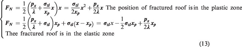
Bearing capacity of coal pillars at different positions of roof fracturing: (a) fractured roof in plastic zone; (b) fractured roof in elastic zone.
The total load on the coal pillar below the broken roof derives from three parts: the load P transmitted from the overburden rock to the hard roof in the goaf, the self-weight P1 of the rock of hard roof, and the self-weight P2 of the direct roof. When 
The roof fracturing position 
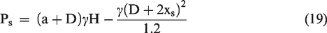
After the hard roof is cut off directionally and crushes some of the coal pillars, the width 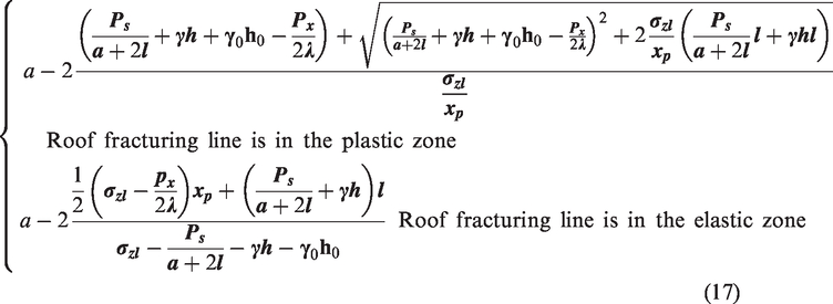
Analysis of factors affecting the position of roof fracturing line
Equation (16) shows that the main factors influencing the position of the roof fracture line are the length of the hard roof, the depth of the coal pillar, the width of the coal pillar, the width of the goaf, the thickness of the coal pillar, the internal friction angle of the coal pillar, the cohesion of the coal pillar, Poisson’s ratio for the coal pillar, the internal friction angle of the interface between the coal seam and the top or bottom plates, the cohesion at the interface between the coal seam and the top or bottom plates, and the support force of the anchor to the wall of the getaway.
Based on the actual situation at the Baidong Coal Mine, the physical and mechanical parameters are as follows: the buried depth of the coal seam
The coal was divided into three categories: the soft coal had a cohesion c of 0.5 MPa and an internal friction angle
Hard-roof length
Figure 8(a) shows how the length of the roof affects the position of the roof fracture line. As the length of the hard roof increases from 0 to 30 m, the distance between the roof fracture line and the inward staggered wall of the gateway increases from 0 to 11 m. With increasing coal strength, the distance between the roof fracture line and inward staggered gateway wall gradually decreases because the increase in the length of the hard roof also increases the load transmitted from the overburden rock in the goaf, thus increasing the width by which the fractured roof could crush the coal pillar below it. When the length of the suspended roof is less than 5 m, the distance between the roof fracture line and the gateway wall increases rapidly. When the length of the suspended roof exceeds 5 m, this increase tends to attenuate.
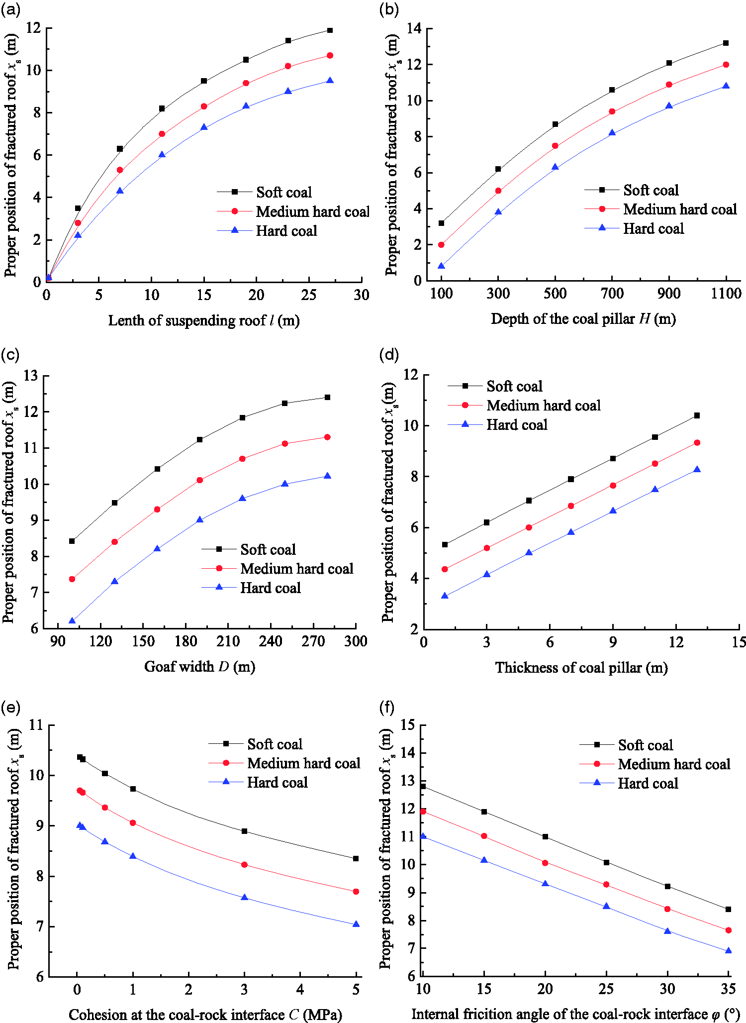
The influence of various factors on the position of roof fracturing line: (a) hard roof length; (b) coal pillar depth; (c) goaf width; (d) thickness of coal pillar; (e) cohesion of coal–rock interface; (f) internal friction angle of coal–rock interface; (g) coal-pillar support force.
Coal pillar depth
Figure 8(b) shows how the depth of the coal pillar affects the position of the roof fracture line. As the depth of the coal pillar increases, the distance between the roof fracture line and the inward staggered gateway wall also increases. With increasing coal strength, the distance between the roof fracture line and the inward staggered gateway wall gradually decreases because the increase in the depth of the coal pillar also increases the load transmitted from the overburden rock in the goaf, thus increasing the width of the fractured roof that could crush the coal pillar below it. When the depth of the coal pillar is less than 400 m, the distance between the roof fracture line and the gateway wall increases rapidly; however, when the length of the suspended roof exceeds 400 m, this increase tended to attenuate.
Goaf width
Figure 8(c) shows how the goaf width affects the position of the roof fracture line. As the goaf width increases, the distance between the roof fracture line and the inward staggered gateway wall also increases. With increasing coal strength, the distance between the roof fracture line and the inward staggered gateway wall gradually decreases because the increase in goaf width also increases the load transmitted from the overburden rock in the goaf, thus increasing the width of the fractured roof that could crush the coal pillar below.
Thickness of coal pillar
Figure 8(d) shows how the coal pillar thickness affects the position of the roof fracture line. As the coal pillar thickness (mining height) increases, the distance between the roof fracture line and inward staggered gateway wall first increases and then stabilizes, with an inflection point in between. With increasing coal strength, the distance between the roof fracture line and the inward staggered gateway wall gradually decreases, and the coal pillar thickness corresponding to the inflection point also decreases because the increased coal-pillar thickness also increases the aspect ratio of the coal pillar, thus reducing its stability and the load that can be borne by the coal pillar. Therefore, under a given load condition, the width of the fractured roof that could crush the coal pillar below increases, and the distance between the roof fracture line and the gateway wall also increases. When the depth of the coal pillar is less than 400 m, the distance between the roof fracture line and the gateway wall increases rapidly. When the length of the suspended roof exceeds 400 m, this increase tends to attenuate. At the same time, with the increasing height of the coal pillar, more of the fractured roof falls and sinks. Thus, appropriately increasing the width of the crushed goaf-side coal pillar helps to control the impact of the sinking of the fractured roof.
Cohesion of coal–rock interface
Figure 8(e) shows how the cohesion at the coal–rock interface affects the position of the roof fracture line. As the cohesion at the coal–rock interface increases, the distance between the roof fracture line and the inward staggered gateway wall decreases. With increasing coal strength, the distance between the roof fracture line and the inward staggered gateway wall gradually decreases because the increase in cohesion at the coal–rock interface also gradually increases the shear resistance of the coal–rock interface, thus increasing the clamping effect of the top and bottom plates on the coal seam and enhancing the ability of the coal pillar against the damage caused by the overburden rock layer. Therefore, the distance between the roof fracture line and the inward staggered wall of the gateway decreases.
Internal friction angle of coal–rock interface
Figure 8(f) shows how the internal friction angle of the coal–rock interface affects the position of the roof fracture line. As the internal friction angle of the coal–rock interface increases, the distance decreases between the roof fracture line and inward staggered gateway wall. Upon increasing the coal strength, the distance between the roof fracture line and inward staggered gateway wall gradually decreases because the increase in the internal friction angle of the coal–rock interface also gradually increases the shear resistance of the coal–rock interface, thus increasing the clamping effect of the top and bottom plates on the coal seam while enhancing the ability of the coal pillar to withstand the damage caused by overburden rock layer. Therefore, the distance decreases between the roof fracture line and inward staggered gateway wall.
Coal-pillar support force
Figure 8(g) shows how the force of the anchor rod supporting the coal pillar affects the position of the roof fracture line. As the support force of the anchor rod to the coal pillar increases, the distance between the roof fracture line and the inward staggered gateway wall gradually decreases. With increasing coal strength, the distance between the roof fracture line and inward staggered gateway wall gradually decreases because the increase in the force of the anchor rod supporting the coal pillar also increased the stability of the coal pillar and the load that can be supported by the coal pillar. Therefore, under the given overburden condition, the increase in the force of the anchor rod supporting the coal pillar also decreases the width of the goaf-side coal pillar that can be crushed, thus decreasing the distance between the roof fracture line and the inward staggered gateway wall.
Characteristics of stress change before and after roof fracturing of large coal pillars
The load actually borne by the hard roof before roof fracturing is
The load actually borne by the coal pillar before roof fracturing is

The load actually borne by the hard roof after roof fracturing is
The load actually borne by the coal pillar after roof fracturing is

The reduction in the coal-pillar load after roof fracturing is

Figure 9 shows the condition of the roof and stress of the coal pillar before and after the roof fractures. The RFPA software is used to simulate the shape of the roof before roof cutting, as shown in Figure 9(a). Before the hydraulic fracturing, the self-weight of the hard roof and the load of the overburden layer both act on the coal pillar, sharply increasing the bearing pressure of the upper-goaf-side coal pillar. This increases the range of the coal-pillar fracture zone and of the plastic zone, along with a high-stress peak and a high-stress range (Figure 9(c)). The RFPA software is used to simulate the shape of the roof after roof cutting, as shown in Figure 9(b). After hydraulic fracturing, the hard roof and the overburden rock formation collapsed. The characteristics of the stress distribution before and after roof cutting are shown in Figure 9(d). On one hand, the original coal-pillar fracture zone and the plastic zone are crushed to form a new coal-pillar fracture and plastic zones. The effective bearing length of the coal pillar is reduced to shift the position of the peak stress to the center of the coal pillar. The bearing capacity of the coal pillar after roof cutting is shown in the AB segment of Figure 9(d). On the other hand, the sinking of the suspended roof decreases the overall load applied to the coal pillar and forms the new support capacity, as shown in Figure 9(d) (OA segment). These two reasons together decrease the peak stress of the coal pillar and the concentration of stress, so that the stress environment of the floor gateway improves, and the strong underground pressure is controlled. In Figure 9,
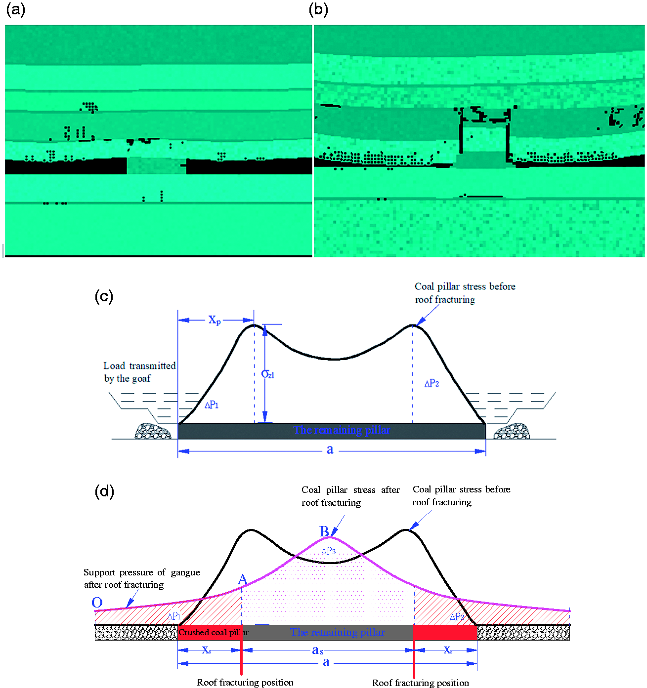
Change in stress due to the fracturing of a hard roof above large coal pillars: (a) before fracturing; (b) after fracturing; (c) the stress distribution before roof cutting; (d) the stress distribution after roof cutting.
Engineering example
To solve the problem of large deformation in gateway 5107 of 5# coal seam, a field test was done in this gateway from 4 November 2017 to 27 November 2017. The test section started 280 m inside the coal-pillar section, and the stress and deformation of the gateway were compared with the section from 0 to 280 m in the coal-pillar.
The on-site parameters were substituted into equation (10) to obtain an 8.2 m wide plastic zone. Next, the parameters were substituted into equation (16) to determine a roof-fracture position of 8.8 m to the inward the side of the gateway. Based on this, a directional hydraulic fracturing scheme was developed to fracture the hard roofs on both sides of the large coal pillars in the goaf, as shown in Figure 10. In gateway 5107 of 5# coal seam, roof fracturing holes were drilled through the top plate. The holes were labeled A and B and were all drilled by using a ZL380 drilling rig into the hard roof above the large coal pillar. The diameter of the boreholes was 50 mm, and the spacing between the holes was 10 mm, and boreholes A and B alternated. Boreholes A had an elevation angle of 75°, a length of 31 m, and a hole sealing position of 23 m. These holes were not slotted. Boreholes B had an elevation angle of 43°, a length of 39 m, and a hole sealing position of 37 m. These holes were grooved with a drill bit. The boreholes were then fractured by using a 63 MPa high-pressure water pump. The boreholes were fractured one by one sequentially while the water pressure curves were recorded. In addition, the water leakage from the surrounding boreholes and coal walls was monitored.
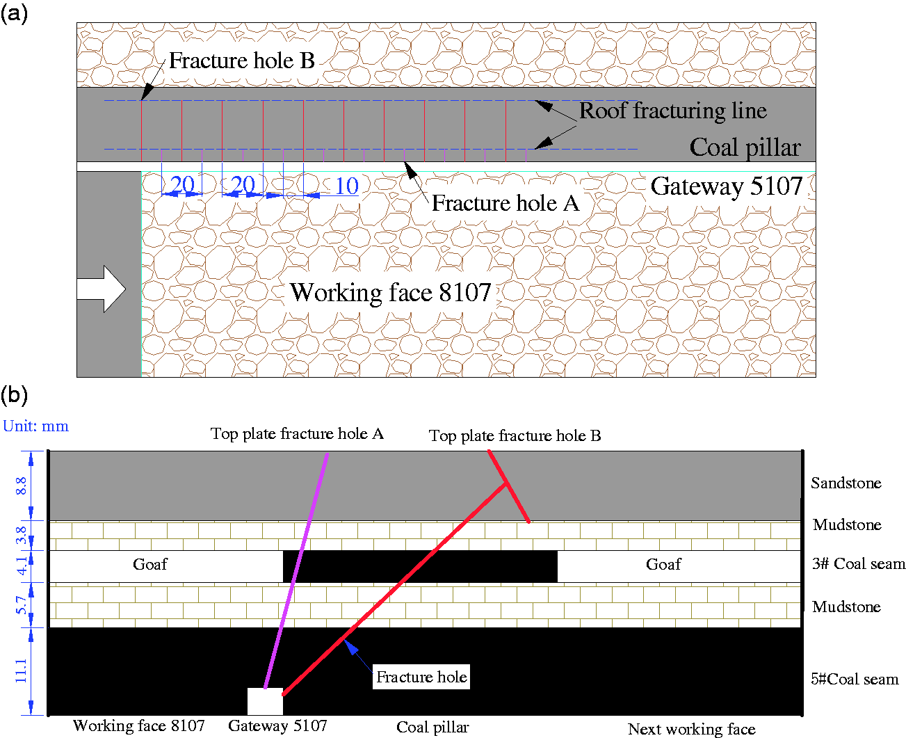
Scheme for double-side directional fracturing of hard roof of large goaf-side coal pillars: (a) layout; (b) cross-sectional view.
Figure 11(a) shows the ZL380 hydraulic fracturing borehole. Figure 11(b) shows the install and fix sealing device and water injection pipeline. Figure 11(c) shows the hydraulic fracturing pump and matching water tank, and the displacement of pump is 200 L/min. Figure 11(d) shows the water pressure curve of the No. 3 hole as an example. The initial fracture of the borehole will occur in a short time after fracturing, and the water pressure is high. And then, the hydraulic cracks will expand evenly and fluctuate smoothly. The water pressure will be relieved when the pump is closed. The water pressure fluctuates around 35–42 MPa, and the maximum water pressure is 43 MPa. The time required for single-hole water injection is 45–60 min, and the volume of water injected is 5000–6000 L. Figure 11(e) shows the phenomenon of water from hole wall and adjacent hole during hydraulic fracturing. After hydraulic fracturing for 15–25 min, water rushes in adjacent boreholes, indicating that the hydraulic crack has extended to a radius of 10 m or more. After fracturing, the hole wall was inspected by using a borehole inspector, the shape of hydraulic cracks in boreholes is shown in Figure 11(f), and the water pressure cracks were clearly identified. The shape of hydraulic cracks is basically vertical without obvious radial cracks, indicating that the hard roof was successfully fractured.
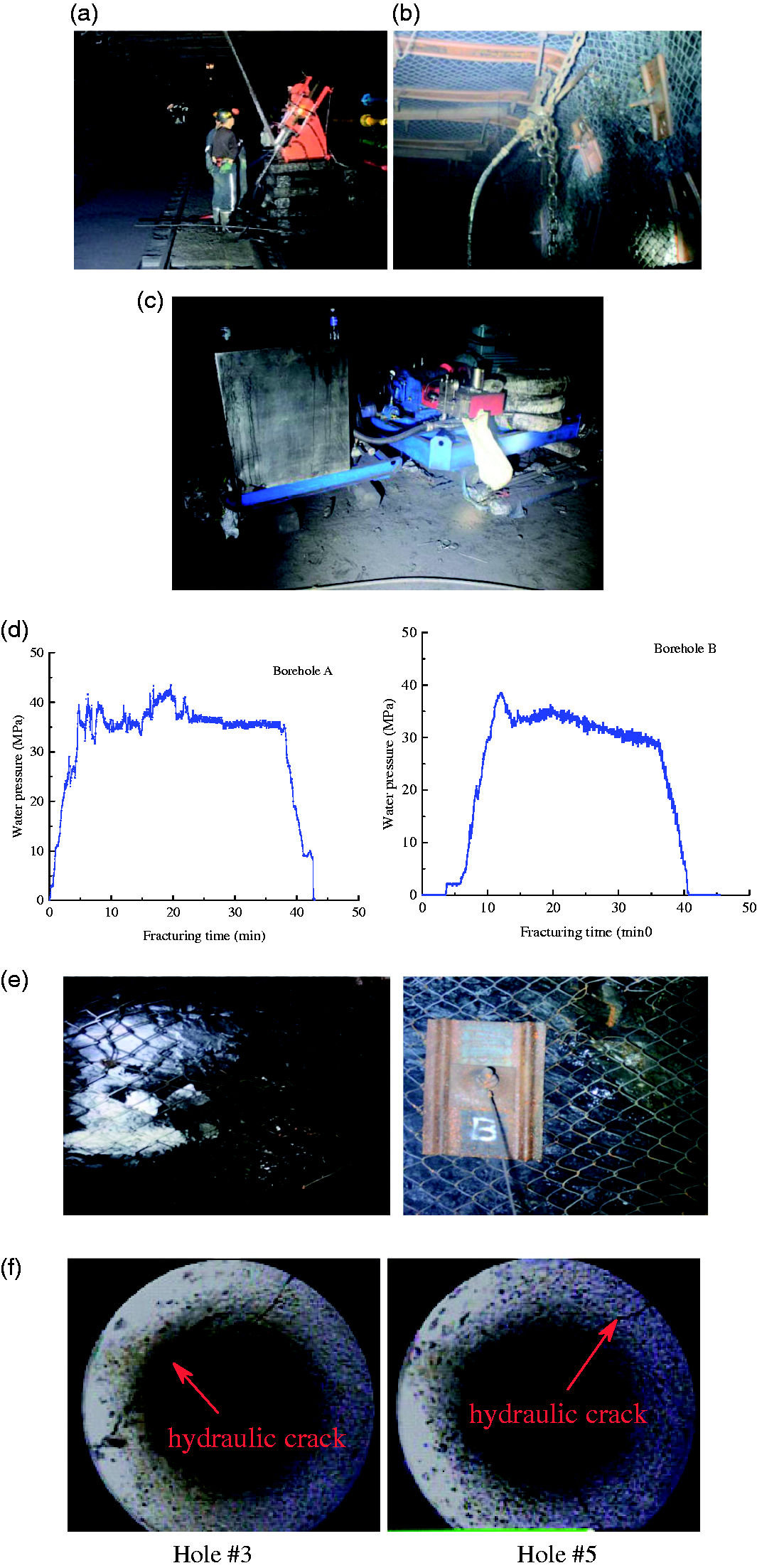
Implementation of double-side directional fracturing of hard roof of large goaf-side coal pillars: (a) drilling fracturing holes; (b) installation of water injection pipeline; (c) high-pressure pump; (d) water pressure curve for hydraulic fracturing process; (e) water inrush from adjacent boreholes during fracturing. Hole #3, Hole #5; (f) morphology of hydraulic cracks on the side wall of bore holes.
Figure 12(a) shows the effect of fracturing the hard roof. Stations A and B were set up in gateway 5107 of 5# coal seam, where station A (B) monitored the deformation of the getaway walls in the unfractured (fractured) area. Gateway deformation included the amount of movement in the top and bottom plates and the deformation of the two side walls.
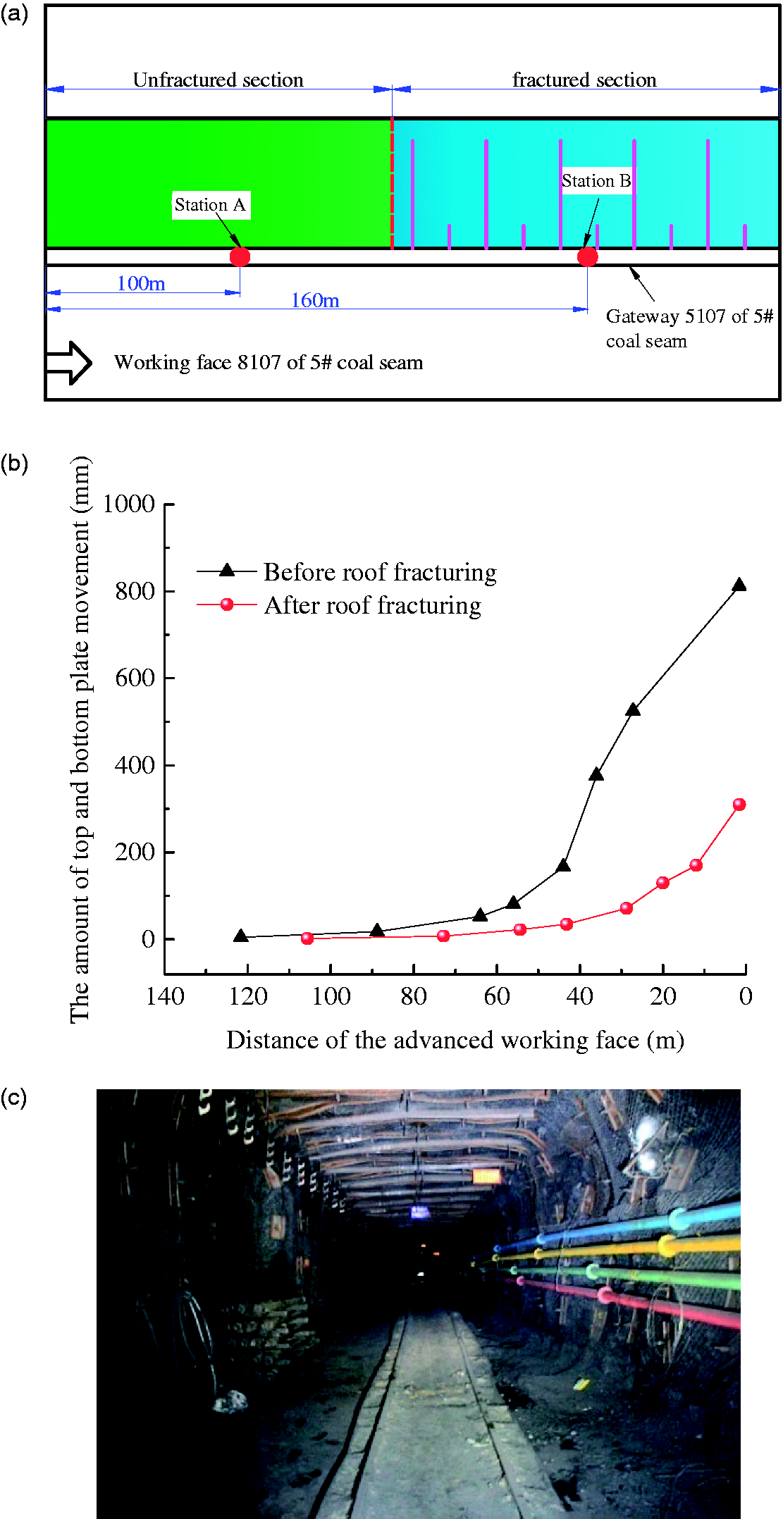
Gateway effect after double-sided directional fracturing of hard roof of large goaf-side coal pillars: (a) monitoring effect of hard roof fracturing; (b) gateway deformation before and after roof fracturing; (c) cross-sectional view of gateway after roof fracturing.
Figure 12(b) shows the deformation of the gateway before and after the roof fractures. After construction was completed, the mine pressure in the gateway was not obvious, and the degree of roof sinking, floor lift, and wall lift was small. The top and bottom plates of the gateway were displaced by a maximum of 340 mm. The maximum displacement of the side wall was 280 mm. Figure 12(c) is the cross-section of the roadway after hydraulic fracturing, and it shows that the deformation of the surrounding rock of the gateway was effectively controlled. Through successful fracturing of the remaining coal pillars and the old roof above them in the goaf on working face 8107 of 5# coal seam, the stress concentration problem under the coal pillars was effectively solved to achieve the expected results.
Conclusion
The double-sided directional fracturing of large goaf-side coal pillars and the distance between the inward staggered roof fracture and the edge of the coal pillars ensure the formation of vertical cracks due to hydraulic fracturing, which is good for roof fracturing but can also crush some coal pillars and thereby reduce the bearing capacity of the coal pillars. The bearing characteristics of the large coal pillars and hard roof are analyzed to establish a mechanical model of the broken-roof sliding instability after directional fracturing and determine the width of the coal pillars that can collapse under maximum overburden load on coal pillars as a reasonable hydraulic fracturing position. The results show that the distance from the mine gateway to the fracture location increases with increasing hard-roof length, coal pillar depth, coal pillar thickness (mining height), and goaf width. In addition, the distance to the mine gateway decreases with increasing coal strength, support of the coal pillar by the anchor rod, cohesive force, and internal friction angle of the coal–rock interface. Engineering tests were applied in coal roadway 5107 of coal seam 5# of the Baidong Coal Mine of the Datong Coal Mine Group. Given the site conditions, a reasonable fracturing length of 8.8 m was obtained. Next, directional hydraulic fracturing was implemented. The comparison of the roof deformation before and after fracturing suggests that this method reduces the local stress concentration in coal pillars, which allows the surrounding rock deformation in roadway 5107 to be controlled.
Footnotes
Data availability
The data used to support the findings of this study are available from the corresponding author upon request.
Declaration of conflicting interests
The author(s) declares no potential conflicts of interest with respect to the research, authorship, and/or publication of this article.
Funding
The author(s) disclosed receipt of the following financial support for the research, authorship, and/or publication of this article: This work was supported by National Key R&D Program of China (2018YFC0604703); National Natural Science Foundation of China (51674248).