
Abstract
In order to mine the coal seam under super-thick hard roof, improve the utilization rate of resources and prolong the remaining service life of the mine, a case study of the Gaozhuang Coal Mine in the Zaozhuang Mining Area has been performed in this paper. Based on the specific mining geological conditions of ultra-close coal seams (#3up and #3low coal seams), their joint systematic analysis has been performed, with the focus made in the following three aspects: (i) prevention of rock burst under super-thick hard roof, (ii) deformation control of surrounding rock of roadways in the lower coal seam, and (iii) fire prevention in the goaf of working face. Given the strong bursting tendency observed in upper coal seam and lower coal seam, the technology of preventing rock burst under super-thick hard roof was proposed, which involved setting of narrow section coal pillars to protect roadways and interleaving layout of working faces. The specific supporting scheme of surrounding rock of roadways in the #3low1101 working face was determined, and the grouting reinforcement method of local fractured zones through Marithan was further proposed, to ensure the deformation control of surrounding rock of roadways in lower coal seams. The proposed fire prevention technology envisaged goaf grouting and spraying to plug leaks, which reduced the hazard of spontaneous combustion of residual coals in mined ultra-close coal seams. The technical and economic improvements with a direct economic benefit of 5.55 million yuan were achieved by the application of the proposed comprehensive technical support. The research results obtained provide a theoretical guidance and technical support of safe mining strategies of close coal seams in other mining areas.
Keywords
Introduction
Close coal seams (CCSs) are two nearby coal seams within the mining range of the minefield that have a very small interlayer distance and strongly affect the mining processes of each other (Sun et al., 2011). Minable or locally minable multi-layer CCSs exist in many mining areas of China (Wang et al., 2013; Wu et al., 2008; Yan et al., 2011), e.g. Xinwen, Pingdingshan, Huainan, Datong, Handan, Shendong and other mining areas. After years of large-scale and high-intensity mining, the reserves of single workable coal seams with superior occurrence conditions become gradually exhausted, jeopardizing further coal production and necessitating the substitution of mines (Liu et al., 2017). Therefore, mining problems of CCSs located within the extended minefield have to be tackled to increase the recovery rate of coal resources and elongate the residual service life of the mines (Tan et al., 2010).
When the distance between upper and lower coal layers during the mining process of multi-layer coal seams is relatively large, the goaf formed by the upper coal seam (UCS) excavation has a feeble effect on that of the lower one. Thus, the observed mine pressure behavior basically coincides with that of regular mining of single coal seam. However, the above interlayer distance reduction results in a coupled mining behavior of the upper and lower coal seams: when its value is so small that these seams are referred to as CCSs, the floor of UCS becomes the lower one roof, and mining of the former induces of damage and failures of the latter (Nasedkina et al., 2008). Moreover, the remaining section coal pillar (RSCP) readily produces the stress concentration in the floor after the mining of the UCS, which stresses are transferred to the lower strata and leading to the roof structure and stress environment of lower coal seam (LCS) changes greatly (Guo et al., 2012; Zhao et al., 2021; Zhu et al., 2010), thus enhancing the mine pressure during mining of the LCS, as compared to that observed during the regular mining of a single coal seam (Sui et al., 2015). The rock burst intensity in close coal seam is higher than other coal seams, and the harm is more prominent.
At present, two major types of mining methods are applied to CCSs (Ghabraie et al., 2017; Kong et al., 2014; Maleki et al., 1986; Sun et al., 2014). The first one is the traditional descending mining of a single coal seam. After the UCS mining, gateways of the LCS are arranged after the roof caving stability is reached. Since this method fails to take into account the floor failure depth of the UCS and stress concentration in the RSCP, its application may cause unreasonable arrangement of gateways of the LCS, strong enhancement of mine pressure, and significant difficulties in the later stage maintenance of gateways. The second method is the coordinated mining of the upper and lower coal seams. Both the upper and lower coal seams are mined simultaneously with a certain interior staggered distance to avoid time effects of the floor failure during mining of the UCS in the mining of the lower one. However, it is quite problematic to organize and comprehensively implement the coordinated mining during the practical production process.
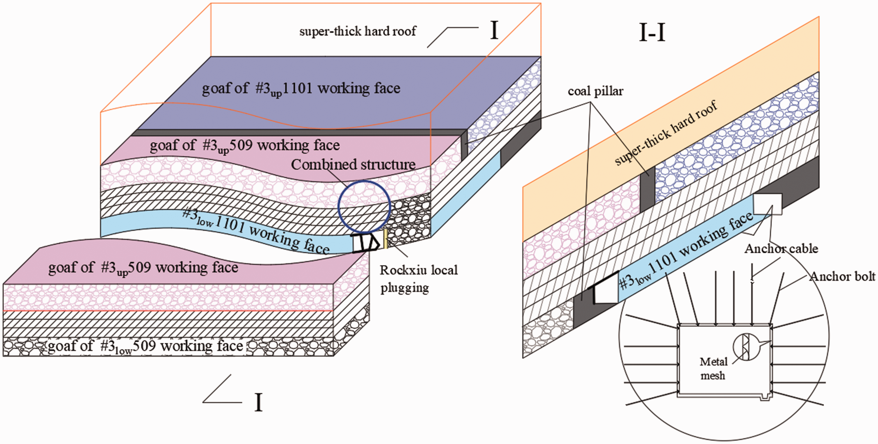
Recently, the technical problems of mining the CCSs became quite urgent. Worldwide studies are performed on such aspects of CCSs mining, such as floor failure depth of the UCS (Feng et al., 2008; Qi et al., 2014), patterns of stress distribution under the RCPC (Poulsen, 2010; Suchowerska et al., 2013), layout of working faces in the LCS (Yan et al., 2015; Zhang et al., 2012), surrounding rock deformation control of roadways (Jiao et al., 2013; Yu et al., 2016), prevention and treatment of mine disasters (Qin et al., 2013; Zhang et al., 2014b), etc. Those studies have yielded certain positive results, which were quite instrumental to a safer coal production in CCSs. However, being focused on a certain specific aspect, previous studies seldom dealt with an integral and systematic collaborative planning of upper and lower coal seams. Coal mining being strongly dependent on the specific mining geological conditions, where any weak link will significantly reduce the safety of other links, including coal seam mining. Using the basic principles of Bucket Theory and the mining geological conditions of ultra-close coal seams (UCCSs, The distance of this two coal seams is oniy 5 m. It is also extremely small in close coal seams. So we call it ultra-close coal seam.) of the Gaozhuang Coal Mine (GCM) in the Zaozhuang Mining Area (ZMA) of China, their joint systematic analysis has been performed, with the focus made in the following three aspects: (i) prevention of rock burst under super-thick hard roof, (ii) deformation control of surrounding rock of roadways (SRRs) in the LCS, and (iii) fire prevention in goaf of the working faces. The results obtained proved that the proposed techniques ensured a safe mining of UCCSs in the GCM, yielded good economic benefits, and provided a theoretical justification for its further implementation in CCSs of other mining areas. The underground coal seams model of Gaozhuang Coal Mine is shown in Figure 1.
Coal seam model of Gaozhuang Coal Mine.
Mine profile and mining technical conditions
As one of the main mines of the ZMA, the GCM is located in the southwest of the Tengnan Coalfield in Weishan County of Shandong province, China. The neighboring coal mines are as follows: the Fucun (East), the Xuzhuang (West), the Jiangzhuang (North), and the Kongzhuang (South). The minefield has a length of 8.5 km from south to north and a width of 2.5–5.5 km from east to west. Earth surface of the minefield is the lakeside alluvial plain slowly declined from northwest to southeast, with a ground elevation of +33–34 m. The GCM was put into operation in 1997, with an initially designed annual production capacity of 0.9 million tons. After several technical renovations, the current annual production capacity has reached 3.5 million tons, and the residual service life is roughly assessed as 26 years. The multi-level vertical shaft was adopted as development method, with the centralized parallel exhaust ventilation applied as the mine ventilation scheme.
The coal mine location and the stratigraphic synthesis column of the relevant study area are shown in Figure 2. The main production level of the GCM is –430 m, and the #3up and #3low coal seams were mined. The entire coal seam presents a monoclinal structure, which is tilted with the dip angle of 4–26°, with the maximum inclination of 31°. Average thicknesses of the #3up and #3low coal seams are 5.0 m and 3.58 m, respectively, with an average interlayer distance of 5 m between upper and lower coal seams, which are typical UCCSs and thus exhibit a coupled mining behavior. The main roof of the #3up coal seam is super-thick hard middle-fine sandstone (Average thickness is 77 m), which breakage readily causes a strong rock burst. Roof of the #3low coal seam is relatively fractured, which makes its maintenance during mining quite problematic. Besides, the area under study has such hazards as the spontaneous combustion of residual coal in goaf.
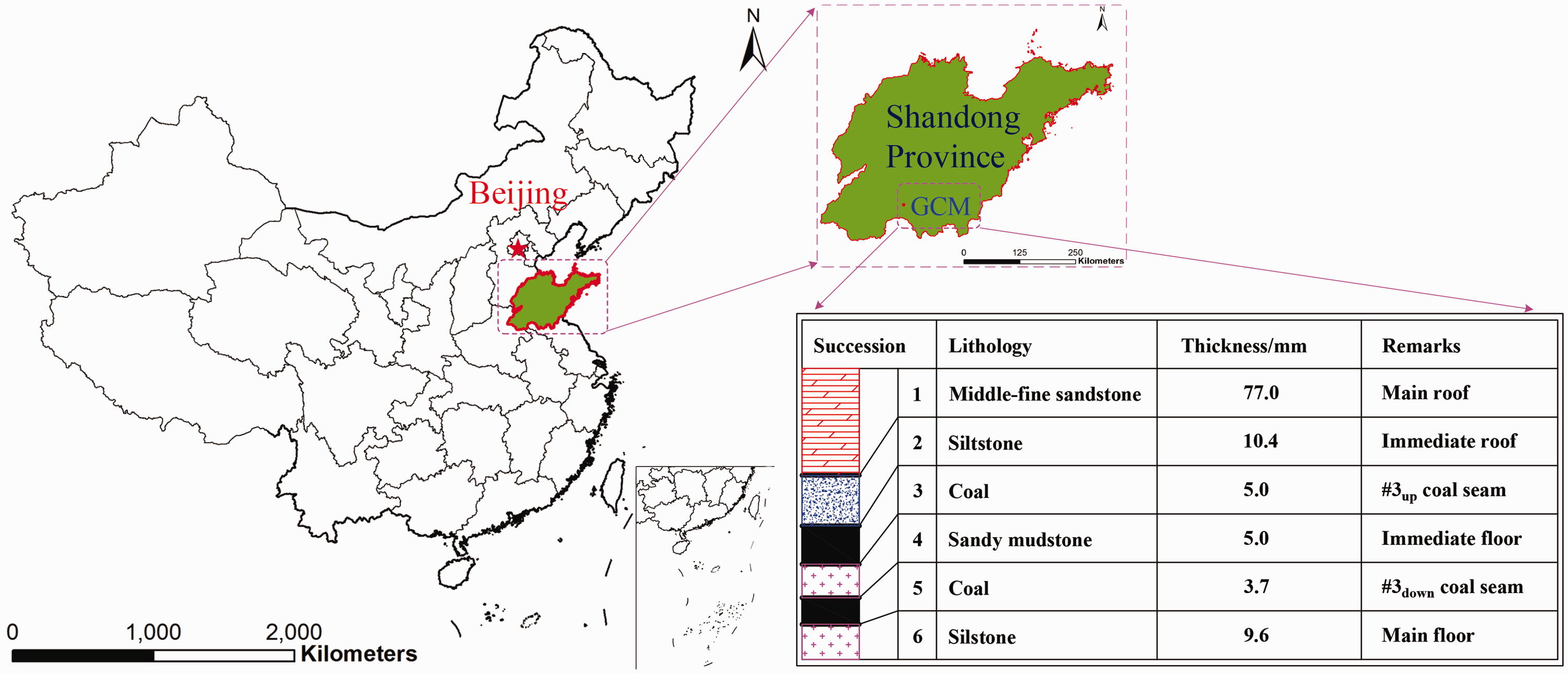
Geographical location of GCM in ZMA.
Prevention technologies of rock burst under super-thick hard roof
Given a strong bursting tendency exhibited by both #3up and #3low coal seams, the following preventing technologies of rock burst under super-thick hard roof were proposed: (i) setting narrow section coal pillars (NSCP) to protect roadways, which prevents the high-stress concentration zone generation in the RSCP of UCS and mining-induced overlying strata, and (ii) interleaving layout of working faces by arranging gateways of LCS below the goaf of UCS, which not only diminishes the pressure of SRRs, but also reduces the risk of rock burst during the LCS mining.
Setting NSCPs to protect roadways
Principles of setting NSCPs
The setting of NSCPs should not only improve the support quality and safety of personnel and equipment inside the roadway but also reduce the risk of potential rock burst hazard. It can be seen from Figure 3 that both yielding and supporting coal pillars can efficiently guarantee the stability of roadway (Zhu et al., 2017). The supporting coal pillar (SCP) can sustain loads applied to the overlying strata, where a sudden stability loss is unlikely. The yielding coal pillar (YCP) can diminish the rock burst risk, and reduce the severity of floor heave inside the roadway, as well as save abundant coal resources. The method of setting the YCP allows a certain deformation of roadway and coal pillar under the action of the lateral abutment pressure, thus transferring loads to surrounding entitative coal, reducing the degree of stress concentration, and inhibiting the coal pillar-type rock bursting caused by a sudden release of the accumulated abundant elastic energy.
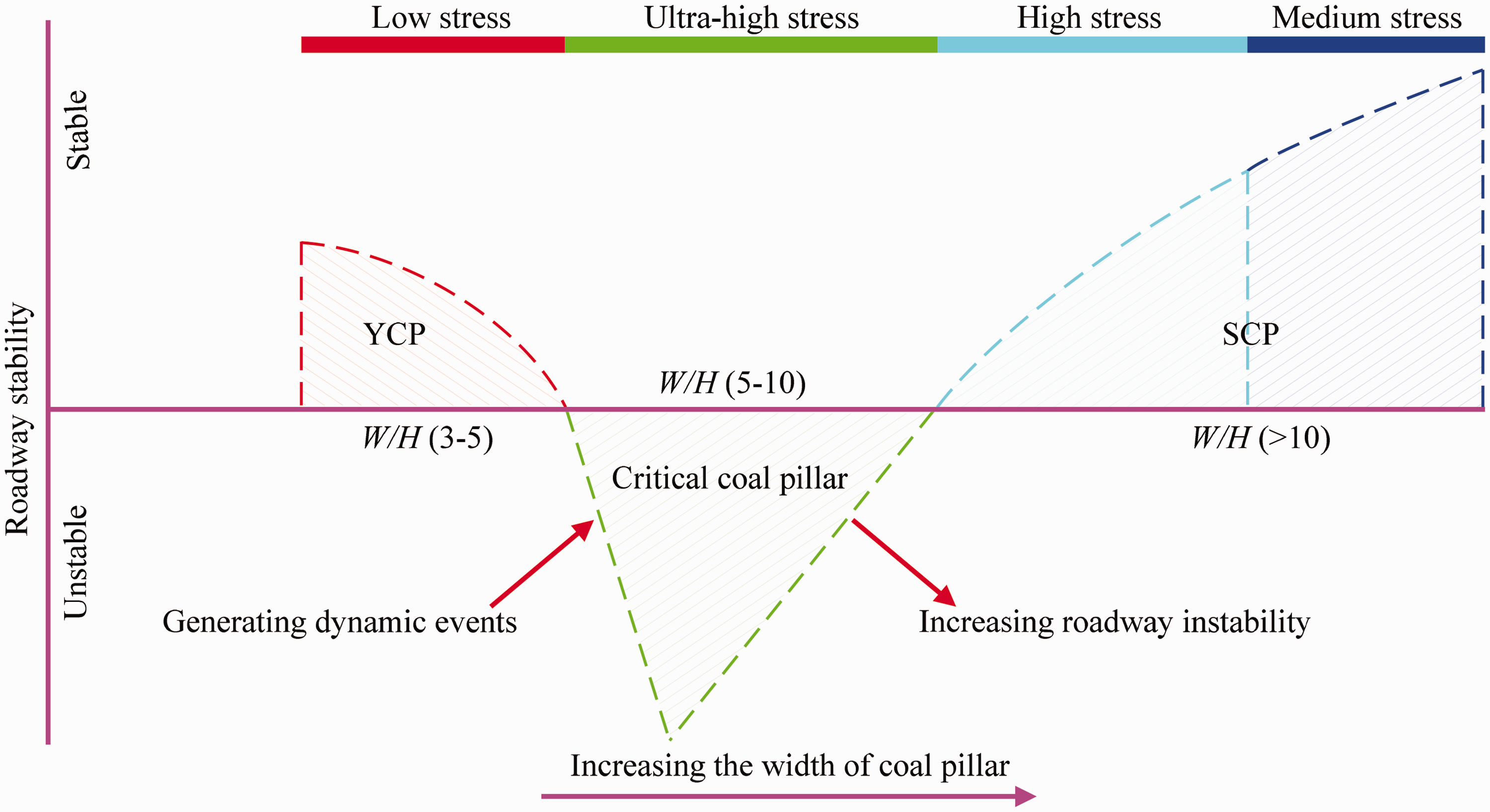
Relationship between the width-to-depth ratio (W/H) of coal pillar and load bearing characteristics.
Effect simulation of preventing rock burst
According to on-site mining geological conditions, the 3 m-wide YCP and 15 m-wide SCP were selected. To analyze the control effect of roof support for two different types of coal pillars, the numerical simulation was performed using FLAC3D (Itasca Consulting Group, USA), which is a three-dimensional explicit finite-difference program for computation of engineering mechanics and is widely used to solve complex problems in mechanics and geomechanics.
Simulation analysis was performed through establishing a numerical model based on two coal pillars proposed above. The numerical model (1040 m in length, 800 m in width, and 280 m in height) was subdivided into 450,320 elements and 470,926 nodes. To enhance the calculation accuracy, the element density was further optimized and adjusted, and the Mohr-Coulomb yield criterion was applied in the numerical simulations. Figure 4 depicts the established numerical model.
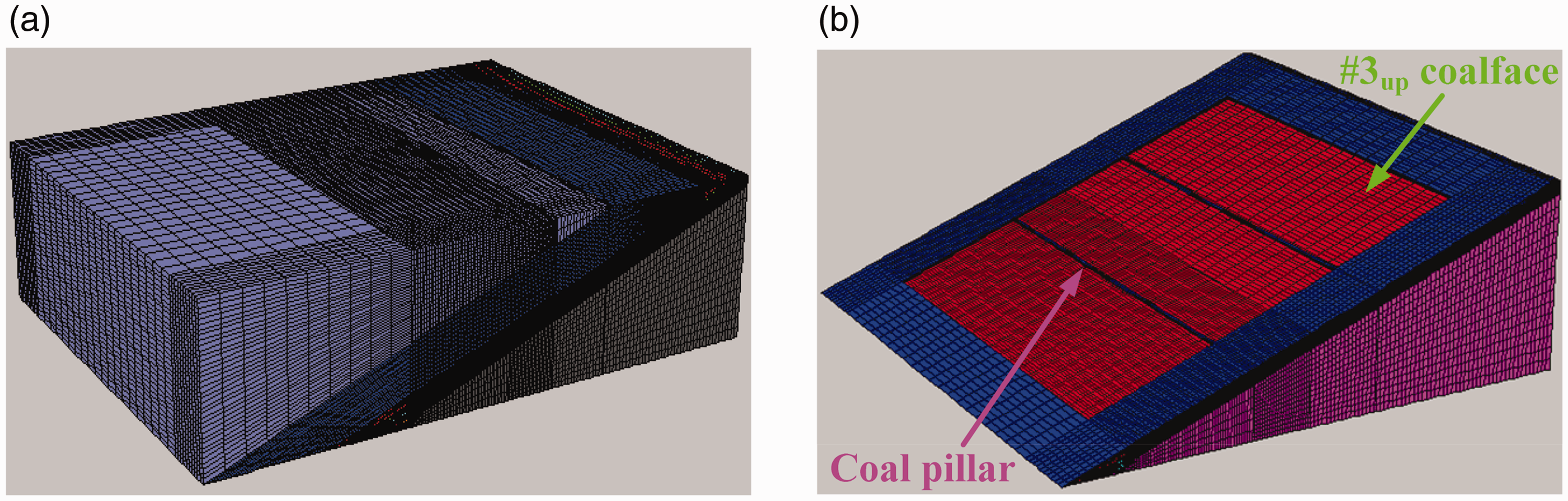
FLAC3D numerical model. (a) Overall view and (b) section coal pillar.
Figure 5 shows the distributions of vertical stresses inside the 3 m-wide YCP and 15 m-wide SCP after mining of #3up507, #3up509 and #3up1101 working faces. The in-situ stress inside the coal pillar was estimated as 13.7 MPa, which exceeded the maximum stress of 3.13 MPa in the 3 m-wide YCP with no stress concentration, and was much smaller than the maximum stress of 29.2 MPa in the 15 m-wide SCP, which had a large stress concentration factor of 2.13. This can be attributed to the fact that the 3 m-wide YCP itself cannot sustain the load and is gradually crushed to final failure, since the elastic energy accumulation does not occur in the YCP with no stress raisers. However, the 15 m-wide SCP with a large stress concentration factor can sustain some loads applied to the overlying strata and store some elastic energy. However, its sudden failure will immediately release the abundant elastic energy, which may cause a severe rock burst and seriously threaten the safe production of working faces.
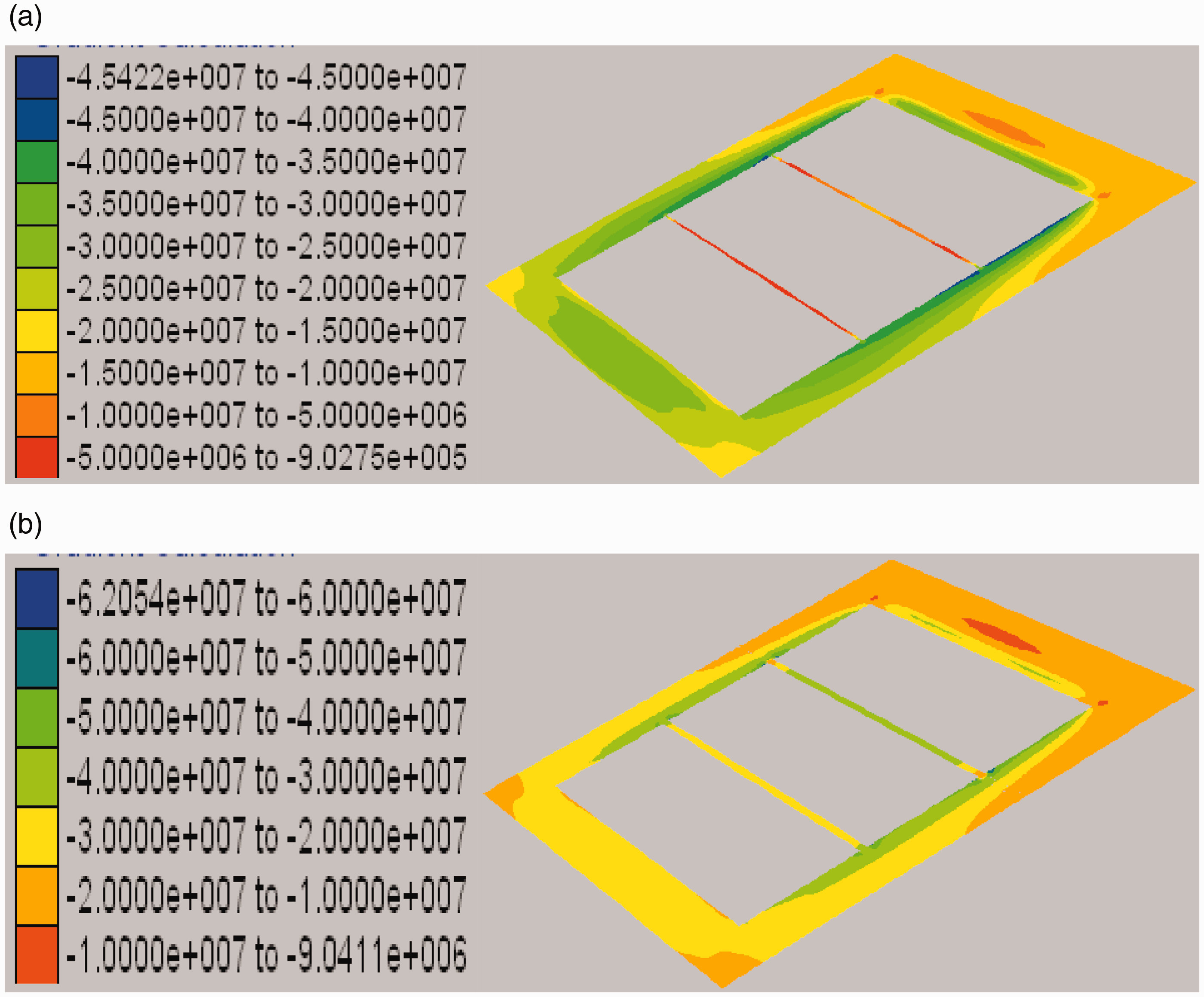
Distributions of vertical stresses in coal pillars at #3up coal seams. (a) 3 m-wide YCP and (b) 15 m-wide SCP.
Figure 6 shows the distributions of vertical stresses in the roof of the #3low coal seams, after mining of #3up507, #3up509 and #3up1101 working faces. Here the stress-affected area of the 3 m-wide YCP is much smaller than that of the 15 m-wide SCP, while the stress distribution along the roof is quite uniform. The stress concentration is observed in the area of the 15 m-wide SCP corresponding to #3low coalf seam, and stresses distributed unevenly along the roof. Therefore, if the 15 m-wide SCP is set to protect roadway, it will be more difficult to protect the fractured roof during mining of the #3 LCS.
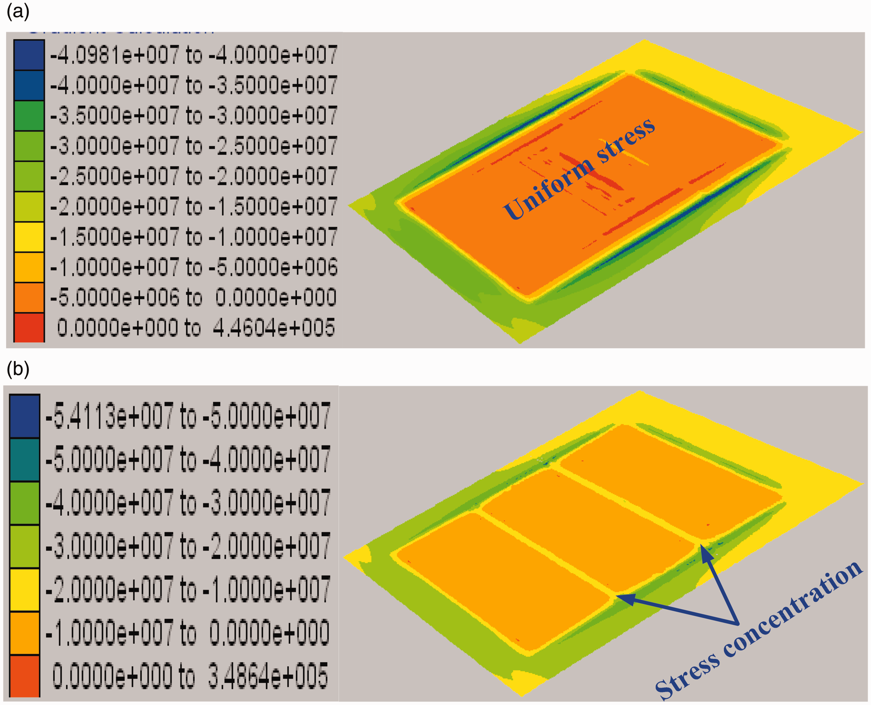
Distribution of vertical stresses in the roof of #3up coal seams. (a) 3 m-wide YCP and (b) 15 m-wide SCP.
Scheme of interleaving layout.
According to the above findings, after the 3 m-wide YCP is set, the entire roof is subsided, a uniform stress distribution along the roof is achieved, and the integrity of overlying strata is retained, which is not only beneficial for preventing rock burst in the #3 LCS and protecting the roof but also improves the recovery ratio of coal resources.
Interleaving layout of working faces
Scheme of interleaving layout
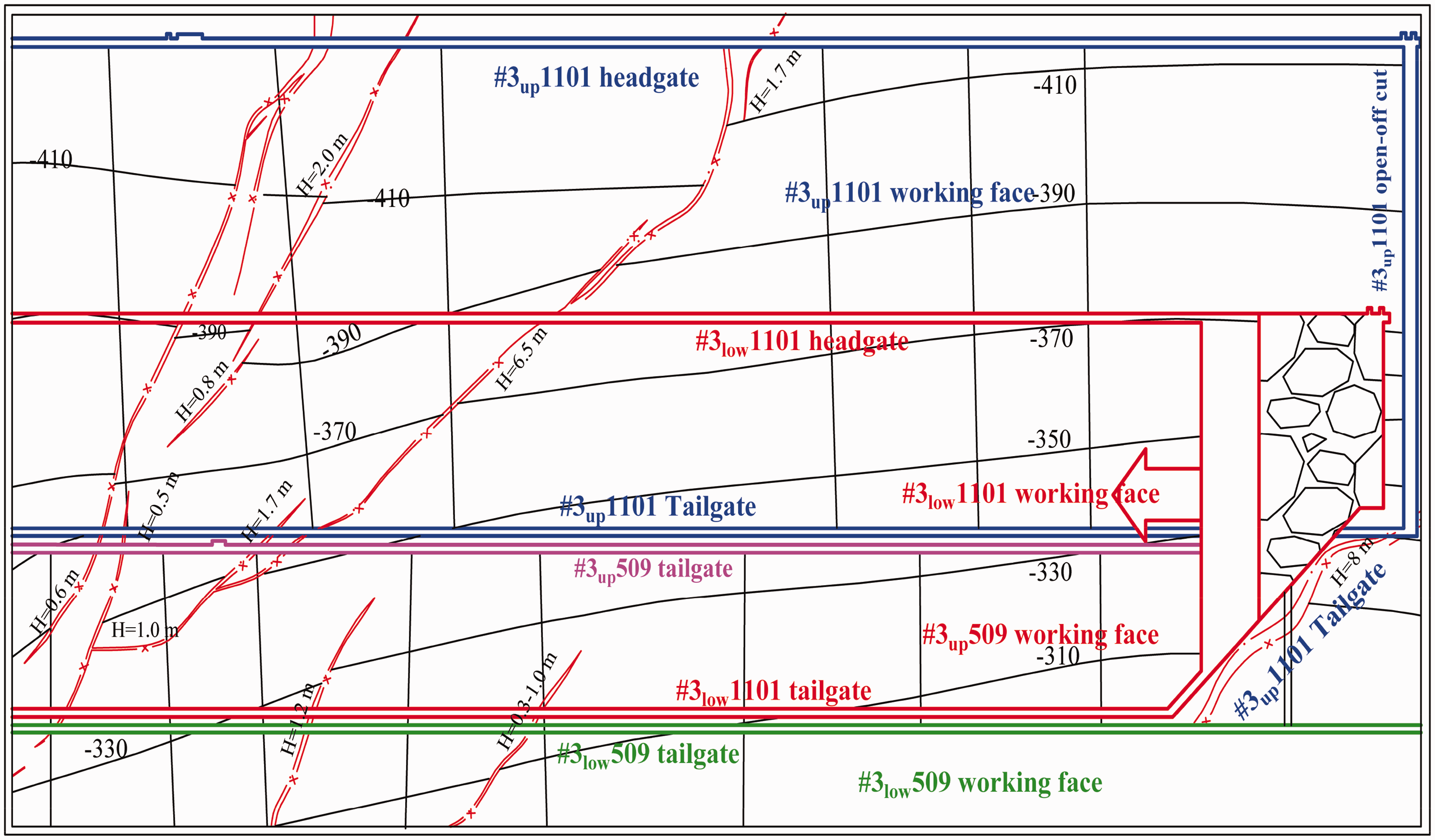
The interleaving layout of the upper and lower working faces was applied during the mining of #3 UCCSs in the GCM, as shown in Figure 7. Here blue and pink lines represent panel 1101 and 509 in the #3 UCS, respectively, while red and green lines correspond to panel 1101 and 509 in the #3 LCS, respectively. The above working faces in the LCS and UCS were arranged using an interleaving layout, which implied that headgates and tailgates of the LCS were arranged below the goaf of the UCS.
Effect simulation of preventing rock burst
Based on the actual on-site conditions, the #3up1101 and #3low1101 working faces were selected to construct a numerical model and then analyze the distribution characteristics of stresses in SRRs when the above coal seams were arranged using the interleaving and overlapping layouts. Figure 8 shows the distributions of vertical stresses in the roof and SRRs of the #3low1101 working face. It can be seen that, when the interleaving layout was applied, the stress distribution along the roof was quite uniform, while the maximum stress of 20.35 MPa appeared at the left side of the roadway, while that in the roadway roof amounted to 13 MPa. When the overlapping layout was applied, the maximum stress of 25.1 MPa also appeared at the left side of the roadway, that in the roadway roof was 18.5 MPa, and the roadway deformation at the coal pillar side exceeded that observed for the interleaving layout. This implies that the influence of RSCP in the #3up1101 working face was not avoided by the roadway roof in the #3low1101 working face when the overlapping layout was applied, in contrast to the interleaving layout, which provided a better roadway protection. Moreover, when the above working faces were arranged in an interleaving layout, no obvious stress concentration occurred in the whole overlying strata. Except for the region around roadway of the #3up1101 working face with a maximum stress of 25 MPa, stresses in other regions were no larger than 20 MPa. According to the above findings, in the mining of UCCSs, when the #3low1101 working face was arranged with an interleaving layout below the goaf of the #3up1101 working face, stresses in its roof were relatively small, and no obvious stress concentration was observed in the SRRs, which is beneficial for the support control and maintenance of roadways. The comparative analysis shows that it is expedient to arrange upper and lower coal seams with an interleaving layout, which is more lucrative for preventing rock burst in working faces of the LCS than the overlapping one.
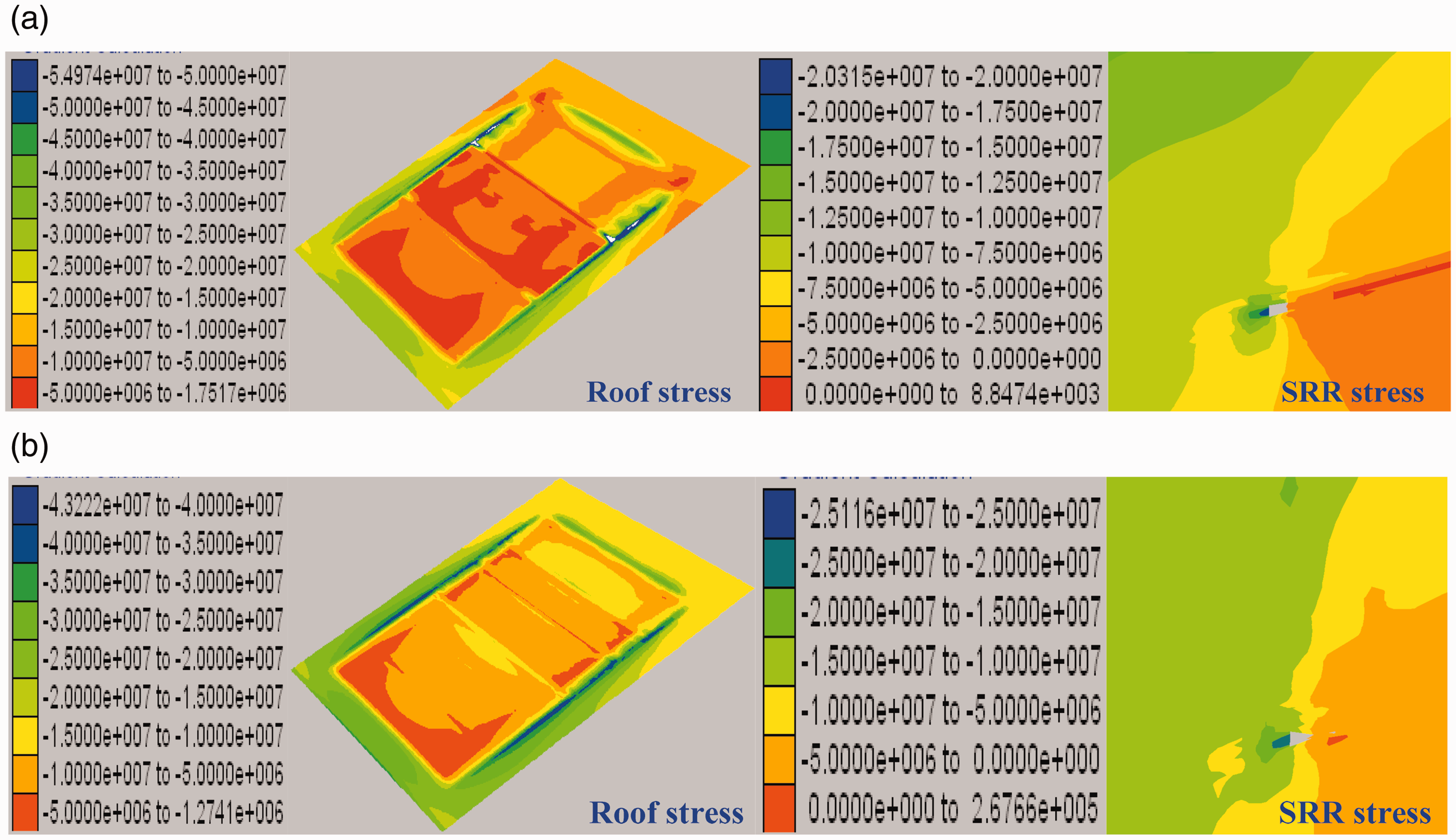
Distribution of vertical stresses in the roof and SRR of #3low coal seam. (a) Interleaving layout and (b) overlapping layout.
Deformation control of SRRs in the LCS
The characteristics of roof structure of the LCS
For ultra-close coal seams, because the direct roof is thin and is affected by the mining damage of the upper coal seam, the cracks in the roof develop, which can be regarded as thin plate structure, when the LCS is mined. On the top of the direct roof is the scattered rock caving after the mining of the UCS. According to the above characteristics, the roof structure of the LCS can be regarded as the combined structure of thin plate and dispersed material, as shown in Figure 9. In the process of coal seam mining, the bearing capacity of this combined structure will be greatly reduced, and it is easy to produce leakage and gangue to form a wide range of empty roof, which poses a great threat to the safety mining of the working face.
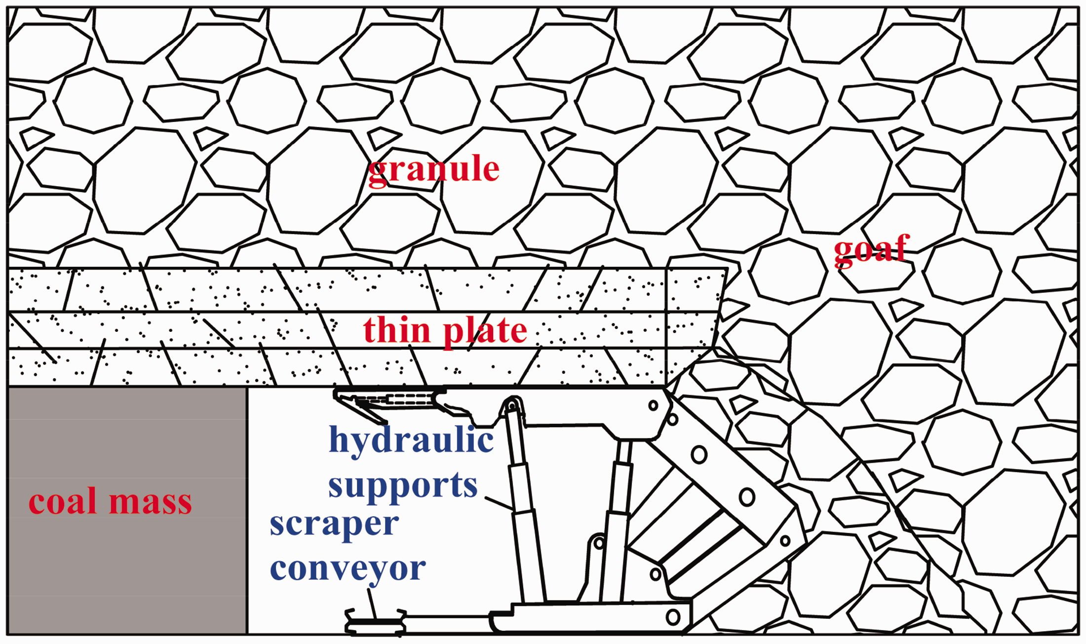
“Thin plate – granule body” combined roof structure.
Roadways support in the LCS
Taking the roadways of the #3low1101 working face as an example, the numerical simulation software FLAC3D was adopted to analyze the deformation characteristics of SRRs, according to which targeted measures for reinforcing and supporting have to be taken. Figure 10 displays the distribution of vertical stresses and plastic zones in SRRs of the #3low coal seam. After working face in the upper section has been mined, the entire roof subsided, and the right side underwent a larger deformation than the left one, due to the fact that a 3 m-wide NSCP was installed at the right side of the tailgate. A small overstressed zone with a maximum stress value of 20.35 MPa appeared at the left side of the tailgate, which indicated the key location that required to be supported. Maximum vertical stresses of the tailgate and headgate were below the in-situ stress and amounted to 13 and 6 MPa, respectively. The roof of the #3 LCS was slightly fractured by the effect of the #3 UCS mining process. The degree of fracture in the tailgate roof was aggravated due to mining-induced influence from the #3low509 working face. Since the headgate roof was relatively stable, only the tailgate required to be reinforced and supported.
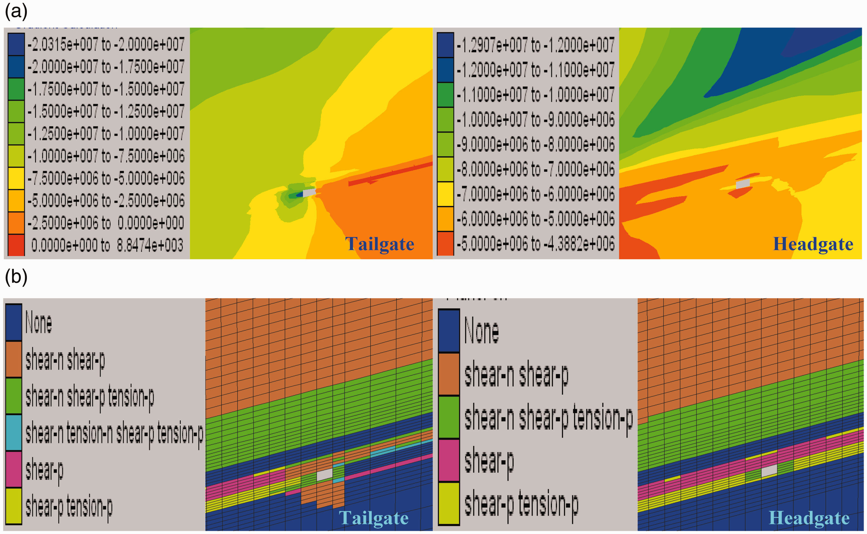
Distribution of vertical stresses and plastic zones in SRRs of #3low coal seam. (a) Distributions of vertical stresses and (b) distribution of plastic zones.
Supporting scheme of the tailgate
The bolt-mesh-ladder-cable combined supporting was applied to support the trapezoid section of the tailgate, as shown in Figure 11. The tailgate had a clear width and height of 4.0 m and 3.5 m, respectively, which corresponded to the cross-sectional area of 14 m2. The specific supporting parameters were determined as follows:
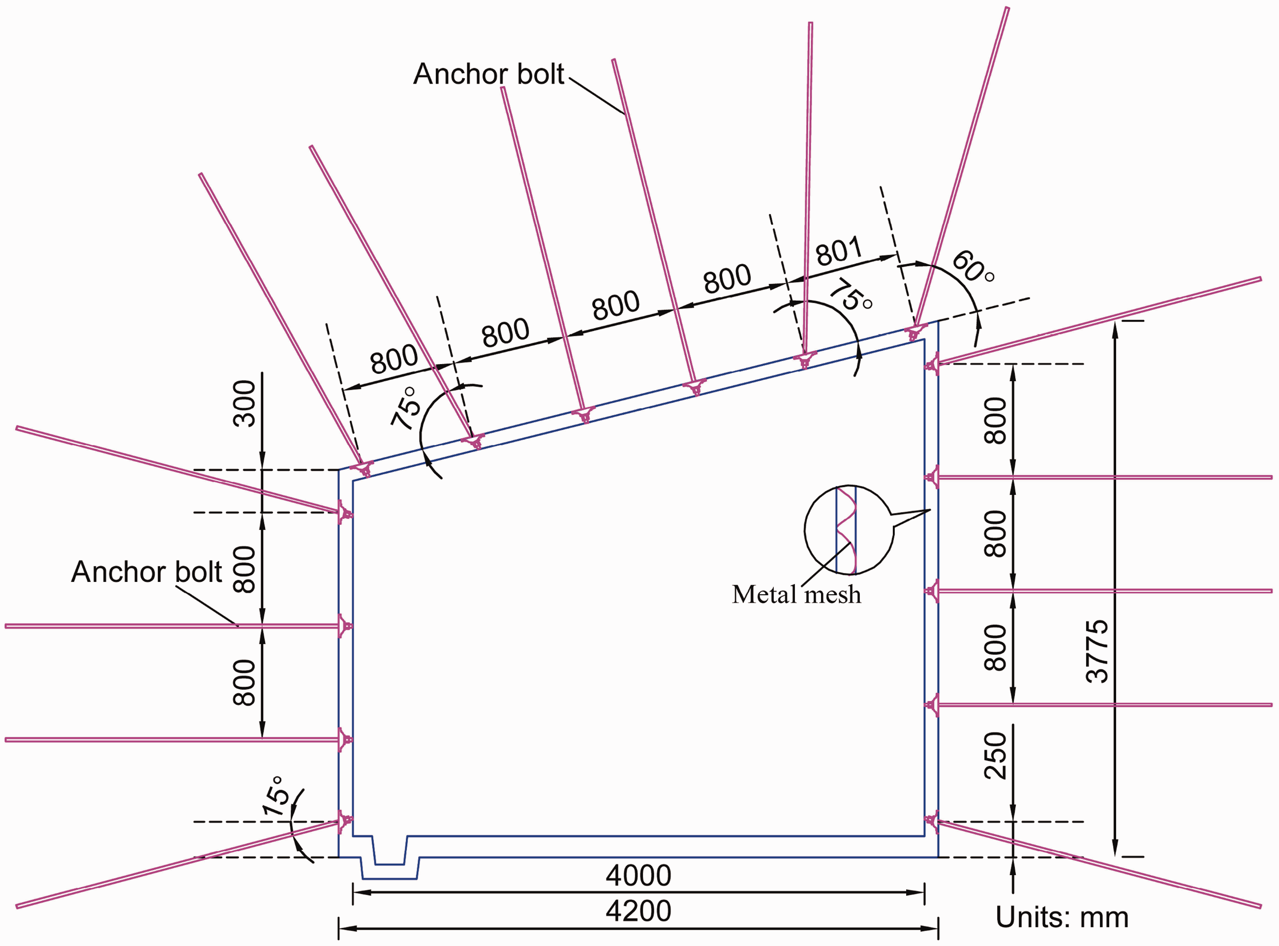
Supporting section of the tailgate.
Roof supporting: The high-strength yielding anchor bolts with prestressing force were used in the roof. The anchor bolts with a size of 20 mm × 2200 mm (Diameter × Length) were arranged with an interval of 800 mm and a row spacing of 800 mm, and anchored using two pieces of CK2335/K2350 resin anchoring agents, with an anchoring length of 1367 mm, and an anchoring force no less than 78.4 kN. Pallet of the anchor bolt made from high-strength metal has a size of 150 × 150 × 10 mm (Length × Width × Thickness). The steel ladder has a size of 4000 mm × 90 mm (Length × Width), a diameter of 16 mm, and an interval of 800 mm. High-strength steel strands with a diameter of 15.2 mm were used as anchor cables at the roof and were arranged in a three-opening layout with a length of 3000 m and a row spacing between anchor cables of 800 mm. Diamond metal mesh at the roof had a size of 4400 × 900 mm (Length × Width) and was weaved using #8 iron wires. The diamond metal mesh had an initial overlap length of zero. When the pressure increased, the overlap length became 100 mm, and #14 iron wires with an interval of 200 mm were used for overlapping.
Side supporting: Metal thread-steel anchor bolts were used at sides. The anchor bolts with a size of 18 × 1800 mm (Diameter × Length) were arranged with an interval of 800 mm and a row spacing of 800 mm, and anchored using two pieces of CK2335/K2350 resin anchoring agents, with an anchoring length of 1287 mm, and an anchoring force no less than 78.4 kN. Pallet of the anchor bolt made from high-strength metal had a size of 130 × 130 × 8 mm (Length × Width × Thickness). Diamond metal mesh had a width of 900 mm and a varying length (which depended on the site condition), and was weaved using #8 iron wires. The diamond metal mesh had an overlap length of 100 mm, and #14 iron wires with an interval of 200 mm were used for overlapping.
Supporting scheme of headgate
The bolt-mesh-cable combined supporting was applied to support the trapezoid section of transport roadway, as shown in Figure 12. The headgate had a clear width and height of 4.0 and 3.0 m, respectively, which corresponded to the cross-sectional area of 12 m2. The specific supporting parameters were determined as follows:
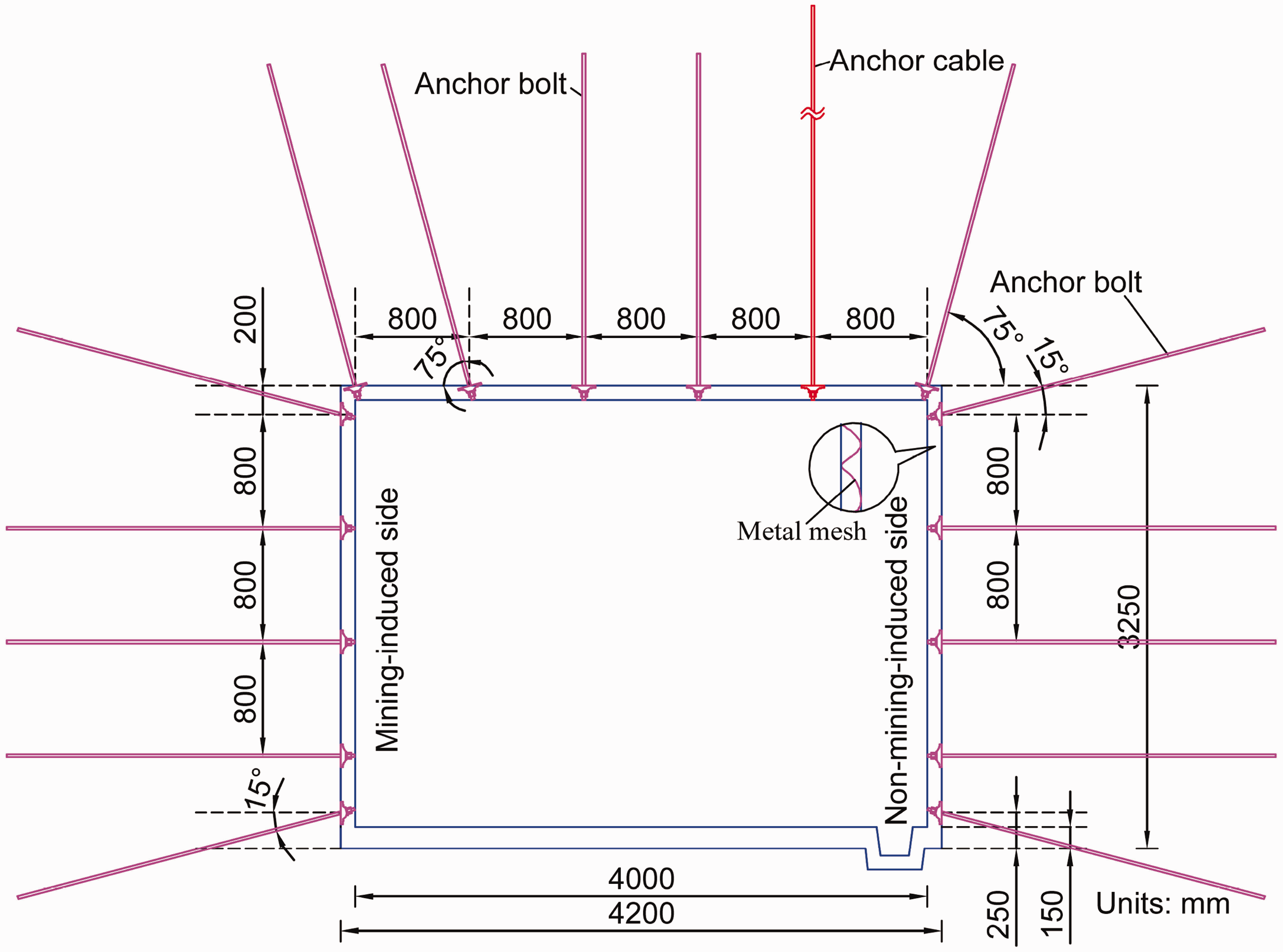
Supporting section of the headgate.
Roof supporting: The metal thread-steel anchor bolt was used in the roof. The anchor bolts with a size of 20 × 2200 mm (Diameter × Length) were arranged with an interval of 800 mm and a row spacing of 800 mm, and anchored using two pieces of CK2335/K2350 resin anchoring agents, with an anchoring length of 1337 mm, and an anchoring force no less than 78.4 kN. Pallet of the anchor bolt made from high-strength metal had a size of 150 × 150 × 10 mm (Length × Width × Thickness). Diamond metal mesh at roof had a size of 4400 × 900 mm (Length × Width) and was weaved using #10 iron wires. The diamond metal mesh had an overlap length of 100 mm, and #14 iron wires with an interval of 200 mm were used for overlapping.
Side supporting: Glass fiber reinforced plastic anchor bolts, which contained belts and polymer mesh with steel wires, were used to support sides of the headgate. The anchor bolts with a size of 18 × 1800 mm (Diameter × Length) were arranged with an interval of 800 mm and a row spacing of 800 mm and anchored using the CK2335/K2350 resin anchoring agents with the same anchoring parameters as those in roof supporting. The polymer mesh and belt had widths of 900 and 150 mm, respectively, and lengths depending on the site conditions. The mesh had an overlap length of 100 mm, and #14 iron wires with an interval of 200 mm were used for overlapping.
Reinforced supporting: When the anchored thickness of the roof anchor bolt in bed rocks was less than 500 mm, anchor cables must be additively set to reinforce the roof supporting. High-strength steel strands with diameter of 15.24 mm were used as anchor cables, which were arranged with an interval of 1600 mm and a row spacing of 1600 mm, and anchored by a pretension of 100 kN with an anchoring length no less than 1500 mm, and the sandstone-anchored thickness of coal seam roof was no less than 2000 mm.
Grouting reinforcement of the local fractured zones
The general term “grouting” implies the injection of grout (i.e. a particular fluid form of concrete used to fill gaps) into fissured, jointed, or permeable rocks to reduce their permeability or increase their strength (Ge, 2006). The so-called “Marithan grouting” involves the two-component polyurethane product called Marithan, which has high adhesive strength and outstanding mechanical properties: when the product is injected into the fractured coal-rock mass, the low-viscosity mixture remains liquid for several seconds and penetrates easily into the fissures, where it expands, sets and seals the threaded zone, significantly improving its load-bearing capacity (Zhang et al., 2014a). Moreover, Marithan, as a polymer reaction product, is usually packed into plastic buckets with a weight of 25–30 kg that are easily transported and ready-for-use in any season without any pollution. Since Marithan reacts with water and generates inert foams, which will not react with acids and alkali, it can be directly used for plugging of the leaks. The grouting pressure of Marithan is adjustable up to 21 MPa, which allows one to control the grouting effect. Finally, the product cost is quite reasonable (below 32.5 RMB/kg), grouting reinforcement through Marithan can achieve the best effects with the least cost.
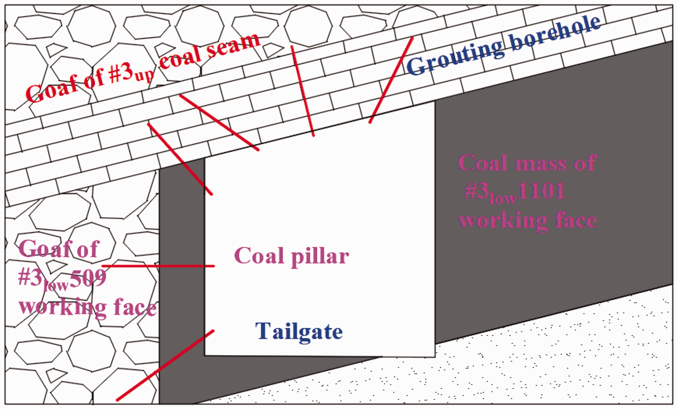
When the SRRs are broken due to geologic structures encountered, Marithan can be grouted into fractured coal-rock masses through pneumatically drilled boreholes using a double-hydraulic pump. Taking the tailgate of the #3low1101 working face as an example, the roof and side with a coal pillar were reinforced by the borehole grouting, as shown in Figure 13. Three grouting boreholes with a dip angle of 60–70°, a depth of 1.6 m, and a diameter of 42 mm were drilled, with a spacing of 1.0 m in each row (spaced by 0.5 m). The normal functioning of all devices was mandatorily checked before grouting. Then two suction pipes are separately inserted into the bucket with resin and the bucket with the catalyst. Piston moved under the action of the pneumatic motor and sucked-in the raw materials, which entered into suction pipes through the piston and then were transported to the injection gun. After the raw materials have been properly mixed and then grouted into boreholes, the grouting slurry rapidly penetrated into fissures and “glued” the fractured coal-rock mass, thus reinforcing the SRRs.
Schematic diagram of grouting reinforcement in the local fractured zone. (a) Air leakage directions in rear goaf and (b) air leakage directions in upper goaf.
Fire prevention technology in the goaf of working faces
The #3low1101 working face has the tendency of spontaneous combustion with a combustion period of 59 days. Coal dust has the explosion hazard with an explosion index of 38.38%. In the particular case of UCCSs under study, the above coal seam goaf will connect with those of the #3up509 and #3up1101 working faces. The resulting air leakage will strongly enhance the spontaneous combustion hazard risk. Therefore, fire prevention technology through grouting in goaf had been proposed to minimize the hazard risks.
Analysis of main air leakage channels
Air leakage in the goaf contributes to most fire hazards in coal mines caused by the spontaneous combustion of coals. To tackle the specific problems related to a possible spontaneous combustion caused by the air leakage in the goaf, an example of the #3low1101 working face was used to identify the main air leakage channels in its goaf. The air leakage pattern in the rear goaf of working face is quite complex, since it is controlled by several factors, such as the collapse situation of roofs in two roadways and the goaf, the negative pressure between the inlet and outlet air flows, air velocity in the working face, the presence or absence of auxiliary roadway, advancing speed of the working face, etc. During the mining of the #3low1101 working face, its rear goaf may connect to goafs of #3up509 and #3up1101 working faces, causing the air leakage from the working faces in the LCS to the UCS. The air leakage scope is controlled by such factors as the roof caving condition in the goaf of UCS, the goaf sealing state, etc. Figure 14 shows the main air leakage channels in the goaf of the #3low1101 working face.
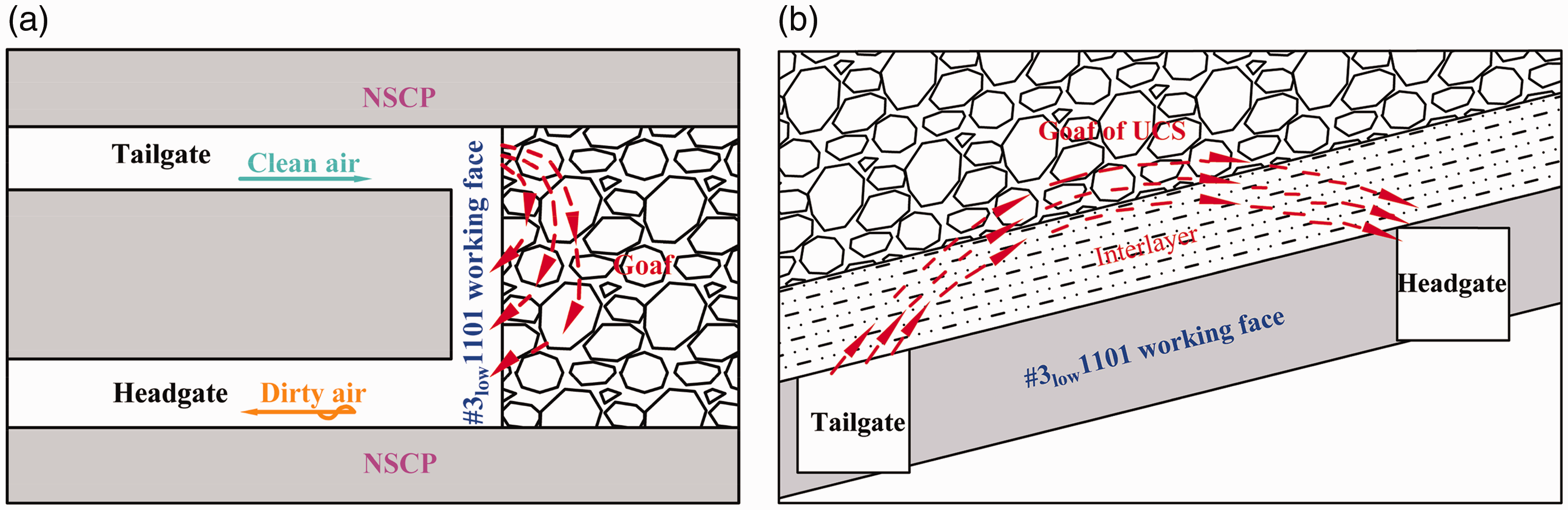
Main air leakage channels in the goaf of the #3low1101 working face.
Fire prevention technology in the goaf of working faces
When there are spontaneous combustions or their pre-requisites in the goaf of working face, grouting of the goaf or hotspots can be performed via the ground grouting station. Therefore, grouting pipelines were installed along the tailgate of the #3low1101 working face, where the towing-pipe grouting and simultaneous mining and grouting could be performed.
Selection of materials for grouting slurry
The main ingredient of grouting slurry is the fly ash produced in power plants. Dust thickener is added as an inhibitor to improve its adhesion. The produced grouting slurry has the basic water-fly-dust thickener ratio of 1:0.3:0.01 (which could also be adjusted according to the actual situation requirements), with an initial dehydration time of 0.5–1.0 h. The grouting slurry could promptly adhere to the coal mass after grouting, wrapping the fractured coal mass and reducing its temperature.
Parametric requirements of grouting materials
(a) Grouting materials should contain little to no combustible or combustion-supporting materials. (b) Diameters of particles should be less than 2 mm, and fine particles should be dominant, where the share of clay with a diameter not exceeding 0.005 mm should be about 60–70%, while in case of application of shale particles with a diameter no larger than 0.077 mm, their share should be in the range of 70–75%. (c) Primary indices of physical properties: grouting materials should have the specific gravity of 2.4–2.8, the plasticity index of 9–14, the colloid mixture content of 25–30%, and sand content of 25–30%. (d) Grouting materials should also be easily dehydrated and have sufficient stability.
Transportation process of grouting slurry
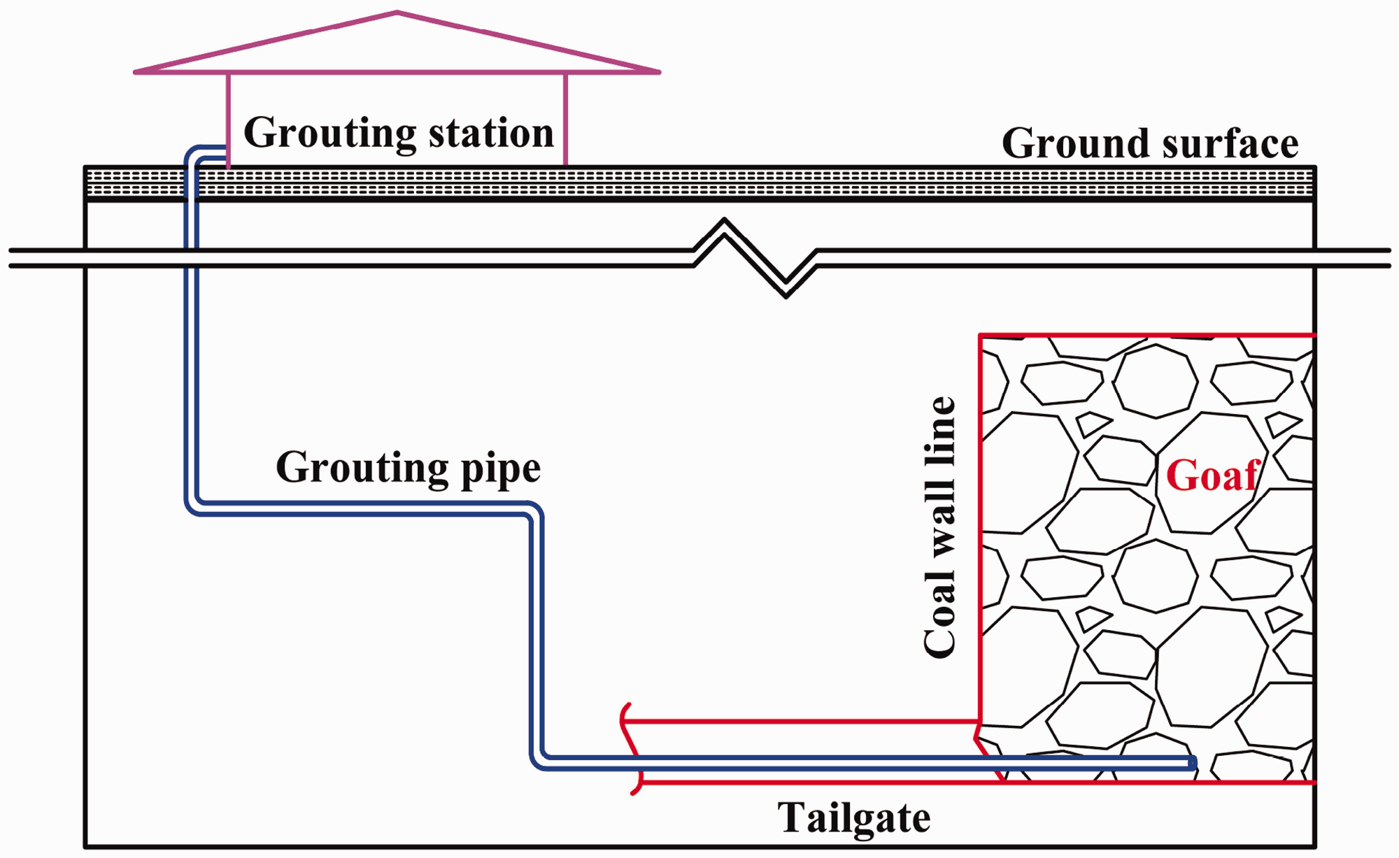
The grouting slurry produced by the ground grouting station was grouted into the tailgate in the #3low1101 working face via grouting pipes, as soon as the working face advanced by about 15–20 m. Steel pipes with a diameter of 50 mm were used as branch pipes, ends of which (i.e. towing pipes) were pre-embedded into the goaf for simultaneous mining and grouting. The 40 m-long towing pipe was assembled using seamless steel tubes with a diameter of 75 mm, which installation envisaged its relocation and repeated usage. Each seamless steel tube/pipe had a length of 5 m and was connected to the adjacent ones via inner connecting wires, the last 2 m-long portion of the pipe being furnished with a borehole for slurry discharging. The grouting technology of the working face is depicted in Figure 15. After the working face withdrawal, two roadways of working face were sealed with pre-set grouting boreholes in compliance with the respective standards. The region nearby the stop mining line of working face is grouted through grouting boreholes, preventing the spontaneous combustion of residual coals nearby the mining stop line.
The grouting technology of working face.
Spraying to plug leaks to prevent fire
When the working face encounters faults and other structures, it is often due to rock cutting through the fault that the rock strata are broken, resulting in air leakage in the working face and spontaneous combustion of the left coal in the goaf. Therefore, plugging measures should be taken timely.
Shotcrete plugging
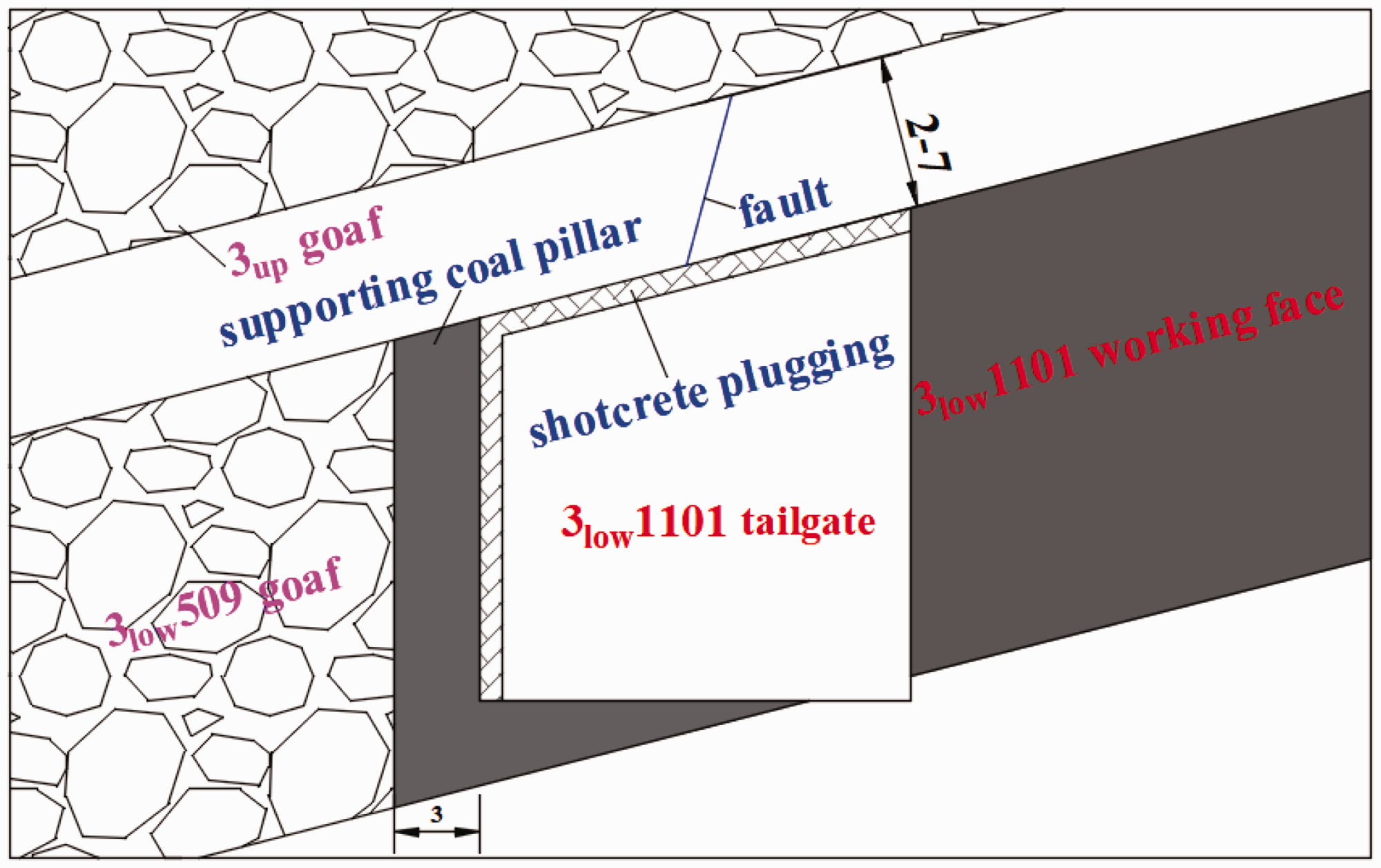
In order to reduce the air leakage in the goaf at the #3up509 working face, the grouting machine is used to carry out grouting on the material roadway along the goaf side and the roof at the #3low1101 working faces, and the thickness of the grouting is not less than 100 mm. Through the use of this method, the air leakage of material roadway is reduced from 74 m3/min to zero, and the hidden danger of air leakage is solved. The grouting plugging process of the material roadway at #3low1101 working face is shown in Figure 16.
Schematic diagram of shotcrete plugging.
Rockxiu local plugging
The end roadway of working face is blocked with Rockxiu material. Hollow walls of 300–500 mm are built in advance, and then Rockxiu is quickly filled between two planks. The plugging can be completed in about 30 min, and the foaming ratio can reach 25 times. The Rockxiu local plugging process is shown in Figure 17.
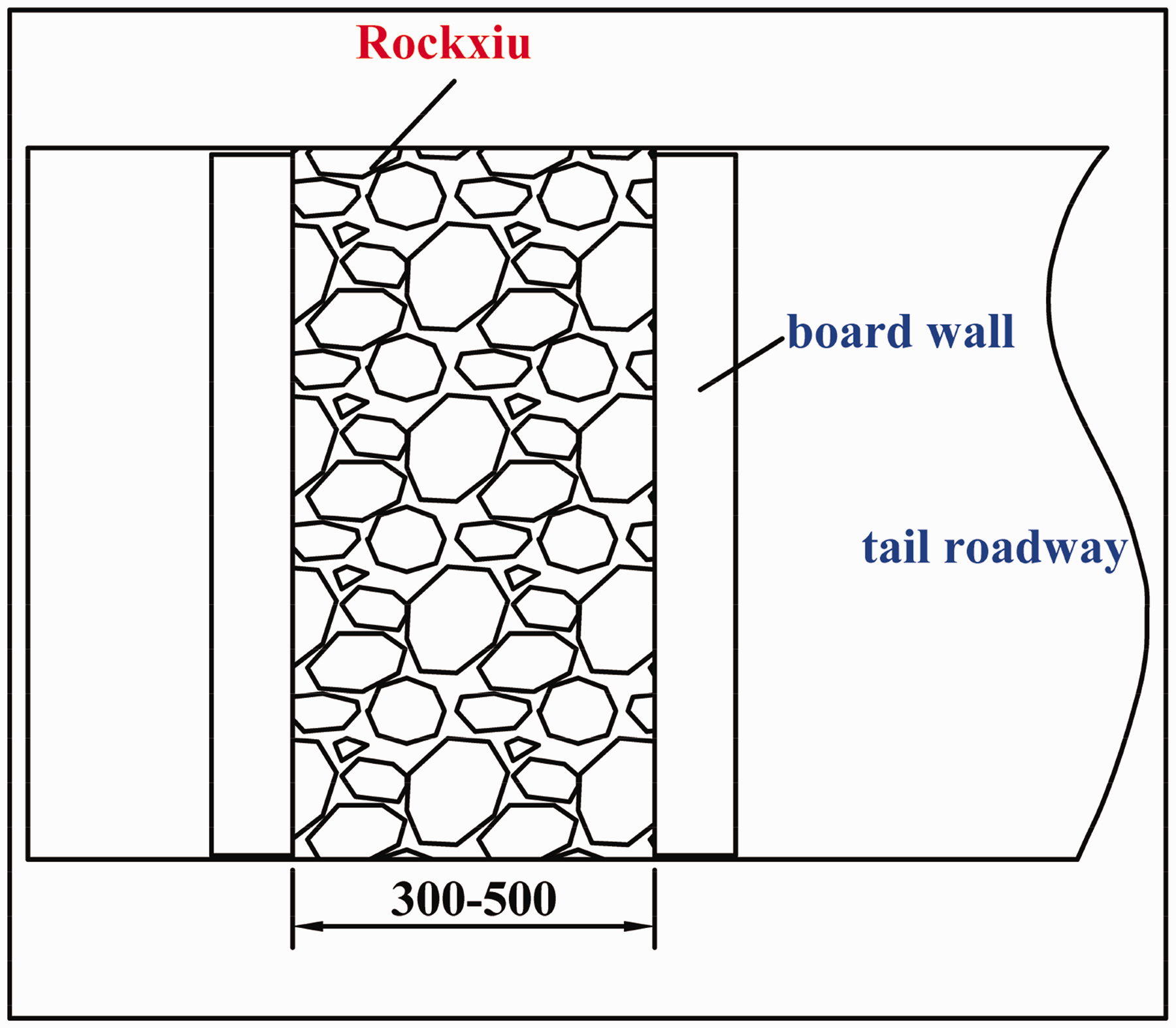
Schematic diagram of Rockexiu local plugging.
Analysis of technical and economic benefits
According to mining geological conditions of the ZMA, technologies were developed including the prevention of rock burst under super-thick hard roof, deformation control of SRRs in the LCS, and fire prevention in the goaf of working face, due to which a safe mining of UCCSs of the GCM was effectively guaranteed, and certain technical and economic benefits were achieved.
a. NSCPs were set to protect the roadways, which reduces the waste of coal resources, and increases the coal production. As compared to wide coal pillars with a length of 15 m, when NSCPs were set in four working faces of the UCS and LCS, 59 thousand tons of coals could be saved, which corresponded to a direct economic benefit of 2.95 million yuan for the coal profit of 50 yuan per ton. b. Through application of the above integrated protection technology, coals in the #3low1101 working face had been safely excavated, which improved the coal resource recovery rate, and effectively reduced the loss of resources by mining the additional 1.05 million tons of raw coals, which corresponded to the direct economic benefit of 52.5 million yuan for the coal profit of 50 yuan per ton.
Conclusions
Based on the results obtained in this case study, the following conclusions can be drawn:
Given the strong bursting tendency exhibited by the #3 UCS and LCS, the following technologies for rock burst prevention under super-thick hard roof were proposed: (i) setting 3 m-wide NSCPs to protect the roadways, which allows one to avoid a generation of high-stress concentration zone in the RSCP of the UCS and mining-induced overlying strata; and (ii) interleaving layout of working faces, which not only decreased pressure of SRRs, but also reduced the risk of rock burst during the LCS mining. The deformation characteristics of SRRs in the LCS were numerically simulated and analyzed in detail, based on which the specific supporting scheme of SRRs in the #3low1101 working face was determined, and the grouting reinforcement method of the local fractured zone through Marithan was further proposed. The #3low1101 working face was used as an example to identify the main air leakage channels in its goaf, including the rear goaf of the working face, and goaf of the UCS. Based on the above analysis, a technology of fire prevention was proposed through the goaf grouting, which strongly diminished the hazard risk of spontaneous combustion of residual coals in mined UCCSs. Through the application of the comprehensive technical support, problems of safe mining UCCSs of the GCM were efficiently solved, with technical and economic benefits corresponding to the direct economic benefit of 5.545 million yuan being achieved.
Footnotes
Declaration of conflicting interests
The author(s) declared no potential conflicts of interest with respect to the research, authorship, and/or publication of this article.
Funding
The author(s) disclosed receipt of the following financial support for the research, authorship, and/or publication of this article: This work was financially supported by the National Natural Science Foundation of China (Nos. 51874278 and 51974291), the Foundation Research Project of Jiangsu Province (No. BK20181357), the “Six Talent Peaks” Project of Jiangsu Province (No. JNHB-087), the Talent Support Project of Jiangsu Association for Science and Technology (No. 2019-134) and the Independent Research Project of State Key Laboratory of Coal Resources and Safe Mining (No. SKLCRSM2020X04).