
Abstract
With the widespread adoption of electronic technology, electromagnetic (EM) interference has become increasingly severe, adversely affecting the normal operation of electronic systems and posing significant threats to human health. EM shielding materials can effectively suppress various EM waves and EM interference generated through space by improving the EM compatibility of electronic systems and electronic devices. Recently, fiber-structure materials have been widely used for EM shielding due to their softness, thinness, and superior shielding efficiency. Therefore, this paper focused on fiber-based EM shielding materials, discussed the basic principles of EM shielding, the types of EM shielding fibers, the efficiency factors of EM shielding fabrics, and presented prospects for the future development of such materials.
In daily life, almost all electronic equipment emits electromagnetic (EM) radiation. EM pollution has become a big problem that endangers people's lives 1 and destroys machine operations. 2 In modern warfare, once attacked by EM weapons, military secrets may be stolen; therefore, more and more attention has been paid to the development of EM shielding fabric (EMSF).3,4 EMSF is a conductive fabric that is combined with metal fibers, typically combined with a conductive coating or integrated with a metal mesh or lattice,5,6 which can be divided into metal fiber fabric,7,8 metal coated fabric,9,10 and conductive coating fabric. 12 In daily life, more and more EM shielding (EMS) textiles are being used, and the EMS textiles sold on the market are mainly made of metal fiber EMSF. 13 Fabrics woven from blended yarns containing metal wires can be used to reinforce walls and windows to prevent the emission of EM energy containing secret information, as well as in our homes and office buildings to prevent EM radiation from cell base stations, telephones, television and radio broadcast antennas, and wireless networks,14,15 so it can be seen that EMSF can be used in a variety of scenarios. This paper summarizes the research progress and development directions of metal fiber EMSF, and provides some new ideas for further research on this kind of fabric.
Overview of electromagnetic shielding
In order to suppress the impact of EM interference (EMI) on people, it is necessary to increase the use of EMS technology, which can effectively prevent the transmission of EM energy at the source, limit the leakage of EM energy in the internal radiation area, and achieve a good EMS effect. 16
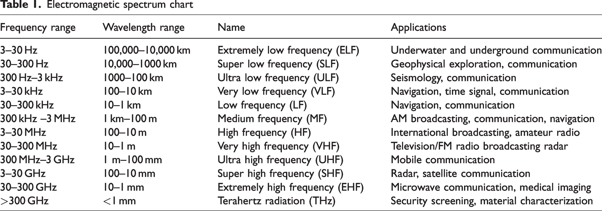
Table 1 focuses on a range of EM radiation frequencies that encompasses everything from radio waves at the lowest frequencies to gamma rays at the highest frequencies. This spectrum is broken down into bands based on their frequency range, and each band has unique applications in fields such as communication, navigation, broadcasting, and imaging.
Electromagnetic spectrum chart
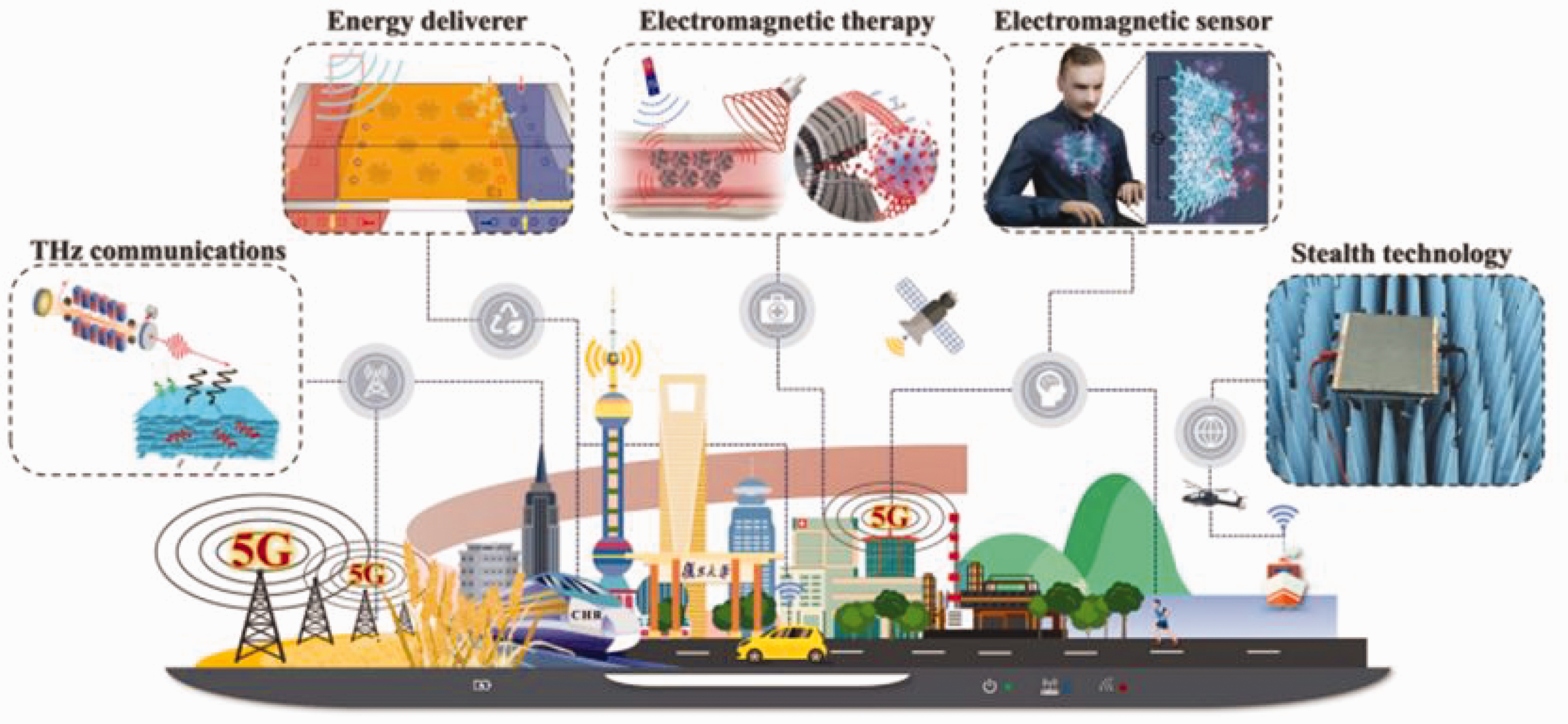
According to the Schelkunoff theory of EMS, 17 the EMS effect of a material is the sum of absorption loss and internal and external reflection loss of the material. The application of EMS material is shown in Figure 1.
Schematic diagram of electromagnetic shielding. 18
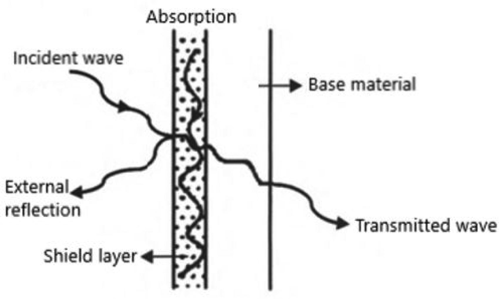
Figure 2 shows that the EM wave is divided into two parts when it radiates onto the shielding material. Part of the EM wave is reflected to the outside world at the interface of the shielding layer. The other part passes through the surface of the shielding layer into the shielding material. Part of the EM wave in the material is absorbed and dissipated by the material itself, the other part is dissipated after multiple reflections on the inner surface of the material, and the remaining EM wave will be transmitted through the material to the other side.
The application of electromagnetic shielding in daily life. 14
At present, EMS material mainly uses the high conductivity of the material itself to form a closed conductive path inside the material, so that the EM waves from the outside can move along the conductive path without penetrating the material. Therefore, in general, the better the conductive performance of the material, the better the shielding efficiency, but with the increase of the frequency of the incident wave, the penetration will be enhanced while the shielding efficiency will be reduced. Another way of EMS is to reflect the incoming EM wave back to the outside world, but this can easily cause secondary pollution of EM waves. The other method is to use conductive coating, 11 which is low cost, has a simple production process and convenient construction, and is widely used. According to the composition, it can be roughly divided into silver, carbon, copper, and nickel. 19
Shielding efficiency is an important index of the EMS performance of materials, which is expressed by shielding effectiveness (SE), and its unit is the decibel (dB). The higher the shielding efficiency value of materials, the better the shielding effect.20, 21
According to the ASTM (American Society for Testing and Materials) D4935-10 standard,
22
the SE can be expressed as follows:

According to IEEE-299 (Institute of Electrical and Electronics Engineers) regulations,
23
the SE can be expressed as for frequencies within the range from 50 Hz to 20 MHz:

In the frequency range from 20 MHz to 10 GHz, the SE can be expressed as follows:

When the EM SE is below 10 dB, the material has almost no shielding effect; when the EM SE is between 10 and 30 dB, the material has a general shielding effect; when the EM SE is between 30 and 50 dB, the material has a good shielding effect, which can be used for ordinary electronic or industrial equipment; when the EM SE is between 50 and 90 dB, the material has a good shielding effect and can be mostly used for aerospace and military electronic equipment; when the EM SE is above 90 dB, the material has an optimal shielding effect, which is mainly used for high-precision instruments. 24
Testing standards for electromagnetic shielding
At present, there are a variety of test methods for the SE of shielding fabric. 25 According to the correlation between the test distance and the wavelength, the test methods can be divided into the near-field method, far-field method, and shielding chamber method. 26 In the near-field environment where the test distance is less than or equal to λ/2π, where λ is the wavelength of EM waves, the EMS materials are suitable for the selection of ionic and intrinsic shielding materials, and the electric and magnetic dipoles are used for near-field shielding theoretical loss EM waves. The near-field test methods include the ASTM-ES-7 double-box method (Figure 3) and the modified MILSTD-285 method. The near-field double-box test method is mainly composed of three parts: the transmitter, the sample, and the receiver. The test method is more convenient, but the main mode is easily affected by the resonant frequency caused by the test. The far-field method is mainly used to test the shielding efficacy of the EMSF on the far field (plane wave) of EM waves. The repeatability of test results is also easily affected by the elastic pad. In the improved MIL-STD-285 test process, attention should be paid to the good tightness of the sample, the gasket, and the opening position of the shielding chamber to avoid a test error caused by EM energy leakage.
Double-box method structure.
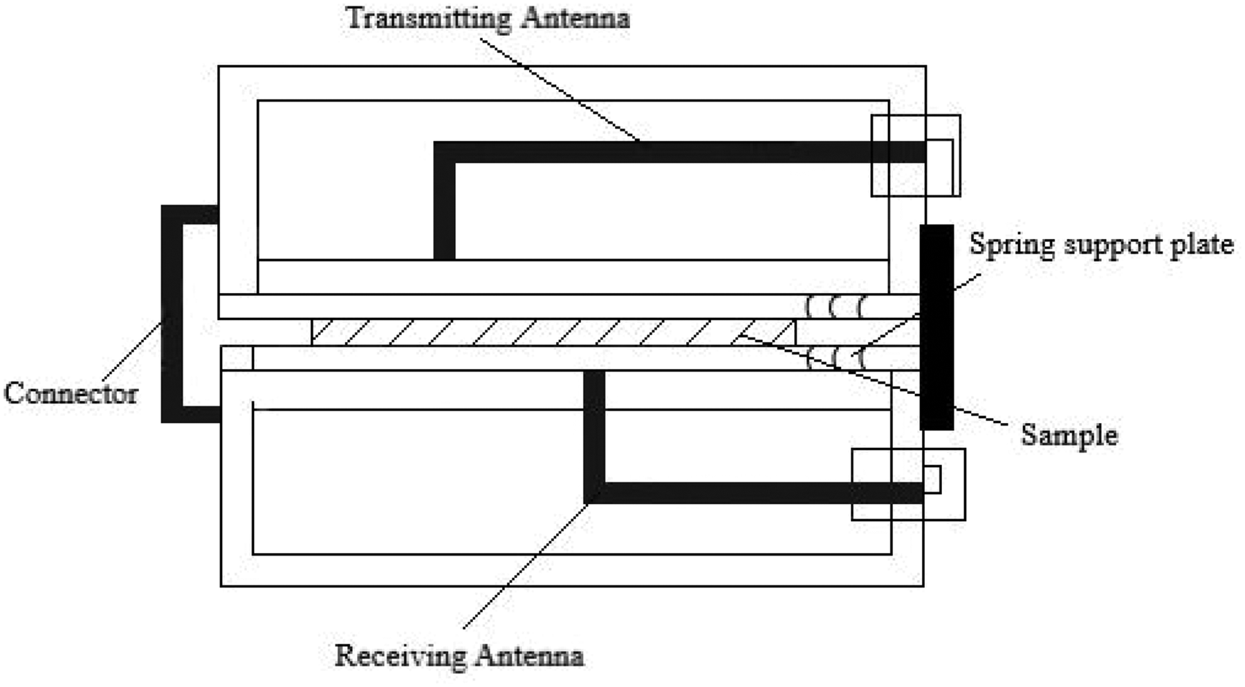
In the far-field environment where the test distance is greater than λ/2π, the coaxial transmission line and flange coaxial method are mainly used for testing. 27 The coaxial transmission line is a double conductor structure, and the EM wave is transmitted between the inner and outer conductors without interference from the outside signal. This method can simulate the process of far-field transmission of EM waves in free space. The principle of the flange coaxial method is similar to that of the coaxial transmission line method; the connection mode of the sample and the coaxial line is further improved, and the contact resistance of the two is reduced. The structure of the flange coaxial test fixture is shown in Figure 4, which includes coaxial lines that are symmetrical about the vertical axis and have a characteristic impedance of 50 Ω. Two coaxial connectors are used to connect a signal source and a signal receiver. The test results of the shielding material placed between the two test fixtures are stable and have good repeatability.
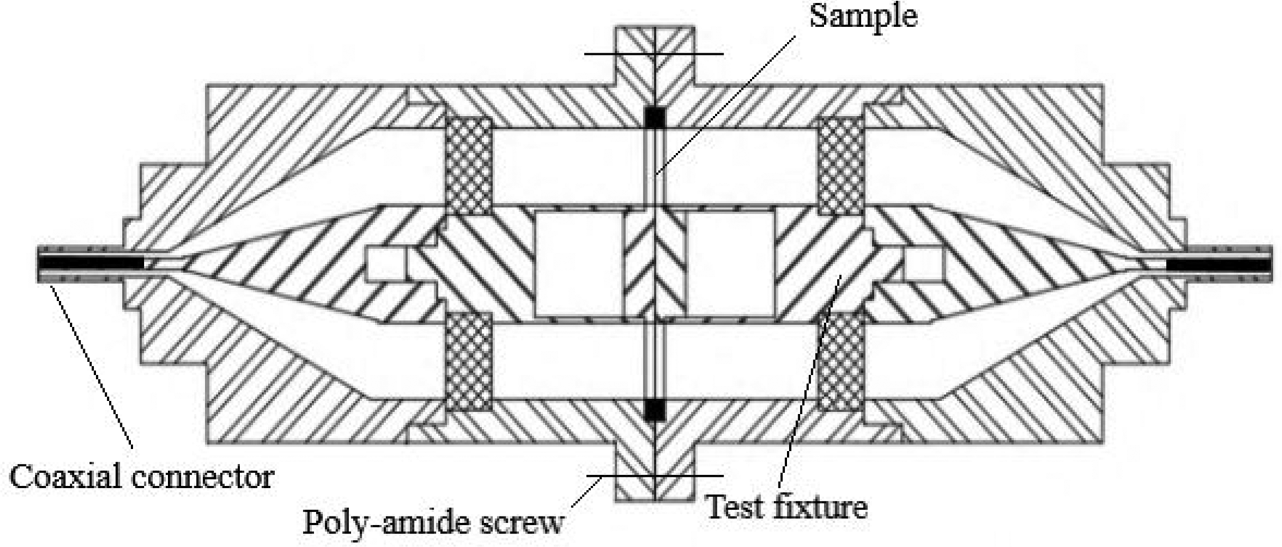
Structure of the flange coaxial device. 27
In the actual working environment, the EM wave emission source is mostly a near-field source or between the near and far fields, and is suitable for testing by the shielding chamber method. This method determines the SE by testing the difference between the transmitted type and the received signal field strength and power with or without EMS materials. The specific principle is illustrated in Figure 5, where a transmitting antenna and a signal generator are placed outside the shielding room, and a receiving antenna and receiving equipment are placed inside. The antenna position and transmission power are kept constant. The SE is equal to the ratio of the received signal level in the unshielded room to the received signal level with the door closed, when the receiving antenna is placed at the same position with unchanged transmitting power. The EM signal provided by the shielded chamber test method is closer to the real EM environment. It can test EM waves with wide frequency and multi-angle incidence, and has little limitation on the sample shape, so it has a wide range of applications. It is crucial to avoid any effect of resonance effects in testing on the test results during the testing process. 28
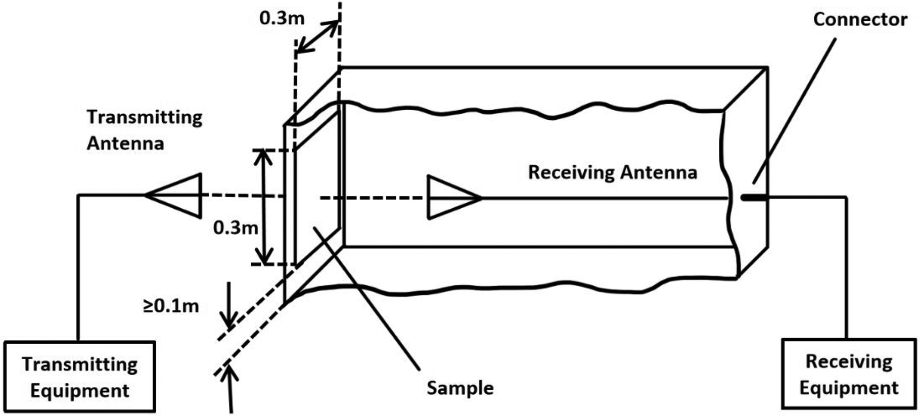
Schematic diagram of the shielded chamber method structure. 28
Two commonly used testing methods for metal fiber fabrics are the flange coaxial method and the shielding chamber method. Xiao et al. 29 conducted comparative tests on the SE of stainless steel fabrics using the flange coaxial method (from 30 MHz to 1.5 GHz) and the shield room method (1–26.5 GHz) to study the SE of samples. The results show that the distribution of the electric and magnetic components of the EM wave in the sample plane is significantly different under the two different test methods and conditions. The shielding chamber method can clearly reflect the directionality of the EM SE of the anisotropic fabric, but the flange coaxial method cannot. When using the flange coaxial test method, the influence of the spacing and aperture of the sample's metal wire arrangement on the SE is less significant than that of the shielded room method, and it is speculated that this is due to the longer wavelength of the EM wave used in the test. Only EMSF with the same spacing of warp and weft yarn and macroscopic isotropic electrical properties follows the same regularity under the two testing methods, and it is also the best structure for shielding EM waves from unknown directions economically and effectively.
The development status of the electromagnetic shielding material of metal fiber
EMSFs are produced by weaving yarns made of fibers with metal characteristics through spinning and weaving processes. The fabrics have the advantages of being lightweight, soft, breathable, and wearable. Fibers with metal characteristics include metal fibers, magnetic fibers, surface metallic-coated fibers, intrinsic conductive polymer-coated fibers, and carbon fibers. EMSFs are obtained by blending, twisting, intertwining, and wrapping these fibers with common textile materials. The resultant fabrics can be used for protective clothing or can be used as composite materials by combining them with a substrate for EMS purposes.
Type of EM shielding metal fiber
According to the EM wave shielding theory proposed by Schelkunof, 17 the shielding of shielding fabric to EM waves mainly depends on the reflection and absorption of the fabric. The sum of reflection attenuation and absorption attenuation is the shielding efficiency SE of the shielding fabric. The higher the value of SE, the better the shielding effect. The calculation formula of reflection attenuation and absorption attenuation 30 is as follows.
Attenuation of reflection:

Attenuation of absorption:

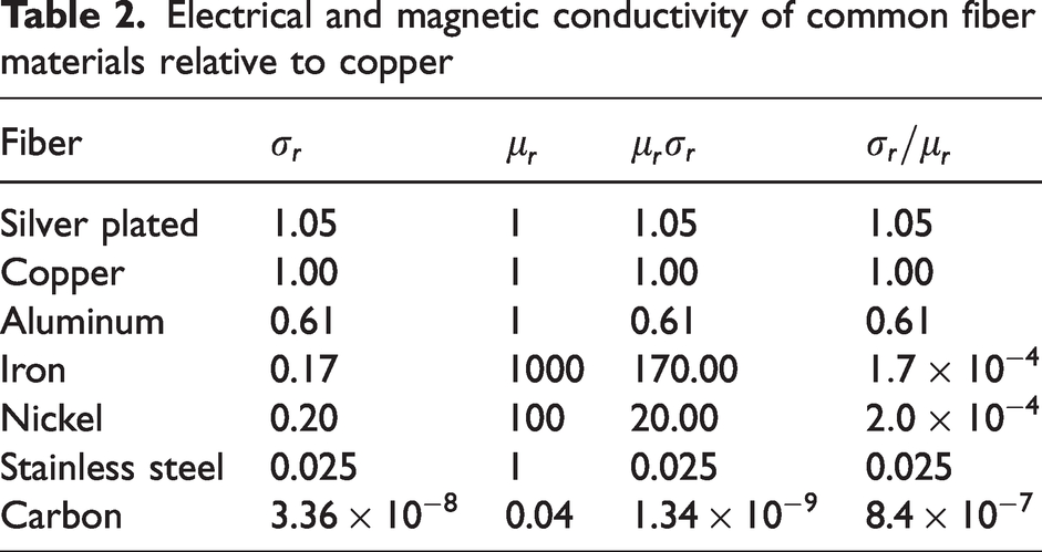
Electrical and magnetic conductivity of common fiber materials relative to copper
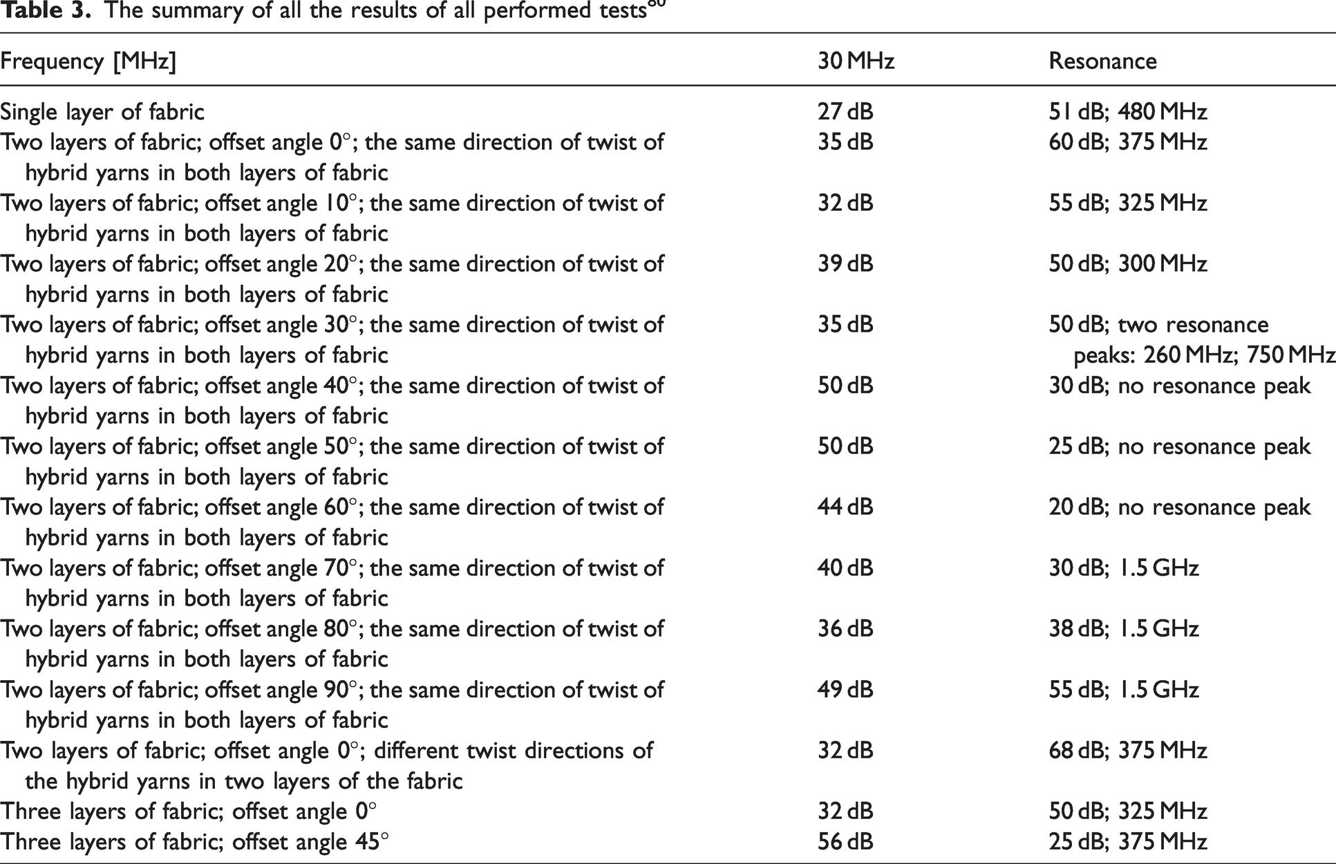
The summary of all the results of all performed tests 80
It can be seen from the above Table 2 that silver, copper, and aluminum have good electrical conductivity and are excellent EM wave reflecting fibers, while iron fibers have high magnetic permeability and can be used as wave absorbing materials. When shielding an electric field and a high-frequency magnetic field, fiber material with high conductivity should be selected. When shielding low-frequency magnetic fields, high-permeability fiber materials are mostly selected. Generally speaking, EMS refers to the shielding of high-frequency EM fields, and fiber materials with high conductivity are preferred. 31 Next, the application of the commonly used EMS fibers, including copper fiber, carbon fiber, stainless steel fiber, and silver fiber, in EMS will be discussed.
Copper fiber
Copper shows high absorption loss and low reflection loss for EM waves, 32 and materials with high absorption loss and low reflection loss are very effective in shielding EM energy. 18 Compared with other materials, copper is also cheaper, so it is widely used in military and electronic shells. However, copper wire is more likely to break during mixing and braiding than stainless steel wire. This may be the reason for the low electromagnetic shielding efficacy (EMSE) of copper composite samples. 33
Yesildag and Kadoglu 34 used copper wires of two different diameters as the core material and cotton yarn as the sheath material to prepare copper core yarn. The shielding effect of these fabrics was measured in the frequency range of 1–6 GHz. The results show that core filament fineness and weft density have a significant effect on EMSE. At 2 GHz, the shielding efficiency of the fabric produced with 0.05 mm copper wire as the core can reach 31.98 dB.
Copper can be combined with other metals to obtain better EMS properties. Tugirumubano et al. 35 investigated the EMS application of samples made of a carbon fiber-reinforced plastic (CFRP) layer and a metal mesh/CFRP plain woven layer. Each sample contains a combination of two conductive metals, such as nickel, stainless steel, or copper, laminated in such a way that the sides of the sample have different metals. Depending on the side of the applied input wave, the sample exhibits different behaviors to attenuate the EMI. The average shielding efficiency of all samples was over 94 dB, and the lowest shielding efficiency was over 82 dB. The combination of nickel and copper appears to have good shielding properties compared to other materials, while the combination of nickel and stainless steel has the highest absorption loss and the lowest reflection loss.
Carbon fiber
Carbon fiber, based on its excellent electrical conductivity, has a strong dielectric loss for EM waves,36,37 making it an ideal EMS material. When an incident radio wave is applied to a carbon fiber material, the structure in which the fiber arrangement direction is parallel to the electric field will produce a larger conduction current inside the fiber, resulting in an effect similar to the reflection of the incident electric field in metals. In a structure where the fiber arrangement direction is perpendicular to the electric field, carbon fiber generates EM wave absorption. 18 When the fiber arrangement direction and the electric field structure are disordered, the reflected electric field can produce a component perpendicular to the incident electric field, which plays a certain role in reflection and dissipation.
In summary, the EMS performance of carbon fiber is mainly attributed to the internal fibers overlapping with each other, forming a conductive network in which carriers can flow. Then, during the carrier flow process, it can interact with the EM field, weaken the propagation of EM waves, and achieve the shielding effect. 31 In addition, carbon fiber has the characteristics of high strength and high modulus along the fiber axis, and is widely used in fiber-reinforced resin composite materials. 38 ,39
By coating the surface of carbon fiber with metal, plating SiC, and deposition of graphite carbon particles, the conductivity of carbon fiber can be further improved, and better EMS materials can be obtained. Carbon fiber EMS composite materials include the filling type and composite type. Composite materials have an excellent EMS effect, but due to their high cost, they are mainly used in high-end fields such as aerospace. 31 Carbon fiber has no crisping and a low holding force, which limits its use in the wearable field, but it can be woven for shielding composite materials. Currently, the most widely used materials for EM shielding are conductive composite materials made of carbon fibers and plastic matrices (such as polypropylene (PP) and polystyrene) or resin matrices (such as epoxy resin and phenolic resin). These materials have excellent electrical conductivity, corrosion resistance, high strength, and lightweight properties, which allow them to effectively prevent the harmful effects of EM radiation on equipment and human health.
Micheli et al. 40 produced a layered composite with a shielding value of up to 80 dB by integrating several aramid and carbon fiber layers in a polymer matrix reinforced by carbon nanotubes (CNTs). Tugirumubano et al. 41 used prepreg carbon fiber and wire mesh to make EMI shielding samples, and the material samples included making ordinary braiding of wire mesh and carbon prepreg and stacking it with prepreg carbon fiber layers. To produce plain fabric, the weft yarn is made of prepreg carbon fiber and the warp yarn is made of silk mesh. In each woven fabric, two yarns of different wire mesh were used alternately. The results show that the material has a high absorption rate and can be used for EMS.
Stainless steel fiber
Stainless steel fiber has been widely studied and applied because of its advantages of low cost, simple preparation, and stable shielding EM wave performance. 42 In the experiment, compared with the stainless steel staple fiber, the stainless steel filament showed better electrical conductivity. 43 The stainless steel fiber fabric has the characteristics of a wide frequency band shielding EM wave and lasting radiation protection effect, good air permeability, soft texture, high strength, washing resistance, corrosion resistance, safety and reliability, comfortable wearing, and convenient processing. It is a simple and practical choice for preventing EM wave radiation. At the same time, the advantages of stainless steel fiber non-woven fabrics in EMS cannot be ignored compared with knitted or woven fabrics. 44 Compared with other metal fibers, stainless steel fibers have advantages in spinnability, usability, and economy. However, they also have disadvantages. Although stainless steel fiber has certain absorption performance for EM waves, it is mainly achieved by reflecting EM waves to achieve effective shielding, which will lead to secondary pollution of EM waves. 45
The amount of stainless steel in the fabric has a great influence on its EMSE characteristics. Su and Chern's experiment 46 clearly shows that the denser structure of stainless steel fabric has a higher EMSE value. However, if fabrics contain stainless steel in only one direction, the warp or weft, they have lower EMSE values. In the EMS analysis, the EMSE of mixed yarn braid samples with different stainless steel fiber contents increased logarithmically with increasing frequency. 47
Tan et al. 48 incorporated stainless steel fibers into PP and acrylonitrile/butadiene/styrene (ABS) copolymer to obtain conductive polymer composites for EMS. The results showed that the crystalline PP matrix required a lower fiber critical filling content than the amorphous ABS matrix to achieve the same SE. Moreover, the shielding mechanism of such materials was mainly based on absorption loss rather than reflection loss. Tan et al. 49 also investigated the effects of surface modification and composite processing on the EMS properties of stainless steel fiber/PP (or ABS) composites. The results indicated that with increasing surface tension of the fibers due to different surface treatment agents, the resistivity of the composites increased and the SE decreased.
Through structural optimization design, the double-layer fabric made of stainless steel fiber has good EMS efficiency. Yu et al. 50 successfully produced a double-layer EMSF that combines a reflective and an absorbent layer. Cotton fabric with polypyrrole coating was prepared by in situ polymerization as an EM wave absorbing layer. A warp knitted fabric made of metal composite yarn containing stainless steel wire was used as the reflection layer of double-layer EMSF, and the EMS and conductive properties of the double-layer EMSF were studied. The results show that the EMS efficiency of the fabric can reach 15 dB in the frequency range from 500 MHz to 1.5 GHz.
Silver-plated fiber
Silver-plated fiber has a high aspect ratio, excellent electrical conductivity, high price, soft texture, does not easily produce static electricity, and has a bactericidal effect. It is often used in anti-EM radiation fabrics. 51 The EMS mechanism of silver-plated fiber fabric is also mainly based on reflection. Jia et al. 52 deposited silver nanowires onto polyester and polyurethane blended fabric, and then obtained CPC/silver nanowire/polyester polyurethane blended fabric by impregnating a superhydrophobic dispersion (CPC) composed of carbon nanotubes (CNT), polytetrafluoroethylene (PTFE) nanoparticles, and fluoroacrylic polymer (Capstone ST-110), submicron polytetrafluoroethylene, and fluoro-acrylic polymer. It has an EMS efficiency of about 51.5 dB in the X-band. Yu et al. 53 compared the shielding performance of silver fiber blended fabric before and after finishing. When the silver fiber content is low, the anti-EM radiation performance of the fabric against low-frequency EM waves is better than that against high-frequency EM waves. When the content of silver fiber is high, the anti-EM radiation performance of the fabric to the higher frequency EM waves is better than that to the lower frequency EM waves. Using a comprehensive comparison of silver fiber fabric content, shielding effect, and price, the silver fiber content of about 21% fabric is the first choice for the production of high-grade EMS worsted wool fabric.
Chao 54 showed that different materials have a great impact on the shielding efficiency and reflection coefficient. In the case of similar spacing, the shielding efficiency of bare copper wire, silver-coated filament, and the stainless steel blended yarn grid arrangement is almost the same, and is significantly higher than that of stainless steel filament. For the reflection coefficient, it can be seen that the silver-coated filament has the best reflectivity and the bare copper wire has the worst.
Development status of electromagnetic shielding fabrics
EMS textile materials can be mainly divided into several categories depending on the preparation method, including mixed woven fabrics of metal wires and yarns, blended fabrics of metal fibers, surface-coated fabrics, and co-spun fabrics.
Mixed woven fabrics of metal wires and yarns
The metals used in mixed woven fabrics of metal wires and yarns include copper wire, nickel wire, stainless steel wire, and occasionally silver wire. However, due to its high price, silver wire is only used in some applications with high shielding requirements, while lead wire is rarely used due to its high density. The SE of mixed woven fabrics of metal wires and yarns is acceptable, but there are also drawbacks, such as rough texture, bulky and heavy fabric, and poor wearability. To improve the wearability of the mixed woven fabrics of metal wires and yarns, fine metal wires are used as much as possible during the weaving process. In addition, appropriate fabric structures such as satin weave and twill weave are selected. Furthermore, by rolling the metal wires into flattened strips and twisting them together with yarns, the flexibility and elasticity of the fabric can be improved, thus reducing the feeling of oppression when wearing. 55
Blended fabrics of metal fibers
To improve the wearability of mixed woven fabrics of metal wires and yarns, scholars both domestically and internationally have developed blended fabrics of metal fibers. This type of fabric is made by pulling metal wires into fiber-like shapes and blending them with wearable fibers before being woven. Metal fibers have excellent properties, such as high strength, thermal conductivity, electrical conductivity, and high-temperature resistance. With the rapid development of functional fibers, metal fibers have also made significant progress and are now classified as new materials. The blending ratio of metal fibers in the fabric is a critical factor that affects its performance. 56 Wearable fibers blended with metal fibers in fabrics used for EM radiation prevention include chemical fibers, cotton fibers, and viscose fibers, with the blending ratio of metal fibers ranging from 10% to 50%. The SE of such blended fabrics ranges from 20 to 70 dB, 57 and they are mainly used for EM protection of human bodies and instruments.
Surface-coated fabric
Surface-coated fabric refers to using a regular textile as the substrate and coating or plating it with a functional layer that has metallic properties, so that each fiber yarn is covered with a layer of metal. In general, most fabrics can be used as the base cloth for metal coatings, with common base cloths including cotton, polyester/cotton blends, nylon, and polyester fabrics. Common plating metals include silver, nickel, copper, etc., and the methods for forming plating layers include chemical plating, in situ polymerization, vacuum plating, magnetron sputtering, etc.
Commonly used single-plating fabric includes silver-plated fabric, 58 copper-plated fabric, 59 and nickel-plated fabric, 60 but these have the disadvantage of being easily oxidized. Therefore, composite plating fabrics that use multiple layers of metal coatings are often used to solve this problem and improve the SE of the fabric, such as copper/nickel-phosphorus/polyester composite plated fabric 61 and amorphous Ni-Fe-P alloy/copper/polyester composite plated fabric. 62 Plating fabrics also has the problem of poor adhesion between the plating layer and the base cloth, so an intermediate layer can be chosen to firmly bond the plating layer to the substrate, such as copper/polyaniline (PANI)/polyester composite plated fabric, 63 which uses PANI as the intermediate layer to make the copper-plated layer more uniform, with a smaller grain size and higher grain boundary density, thus enhancing the bonding strength of the substrate and improving the wear resistance. Similar fabrics include Ni/PANI/polytrimethylene terephthalate (PTT) composite plated fabric 64 and silver/PANI/polyester composite plated fabric. 65
Kim et al. 66 used magnetron sputtering technology to successfully form an Ag film on the material surface and achieved good shielding performance in the 30–1000 MHz frequency band, with the specific value reaching around 45 dB. Savrum and Aguila 67 used magnetron sputtering to deposit a tungsten silicide nanostructured film with a thickness of 30.7 μm on the surface of a ZnS substrate, and the shielding performance of the resulting material reached 53 dB at a frequency of 2000 MHz.
Blend spinning fabric
Blend spinning fabric refers to blending inorganic particles or powders that have EMS effects with commonly used fiber slices and then spinning them to obtain fibers with good conductivity, and then using these fibers to weave fabrics. The blend spinning method can prepare conductive fabrics with a long service life and low production cost, but the shielding effect is not strong, especially at high frequencies, and the process of blend spinning is complex, requiring consideration of many process factors, such as the affinity between the conductive phase and the matrix, thermal stability, thermal expansion coefficient, etc. This promotes the research on EMS fibers produced by blend spinning to develop towards optimizing the arrangement of fillers and improving the performance of fillers, so that these fabrics can have good mechanical properties, shielding properties, and processability simultaneously.
Electromagnetic shielding fabric products available on the market
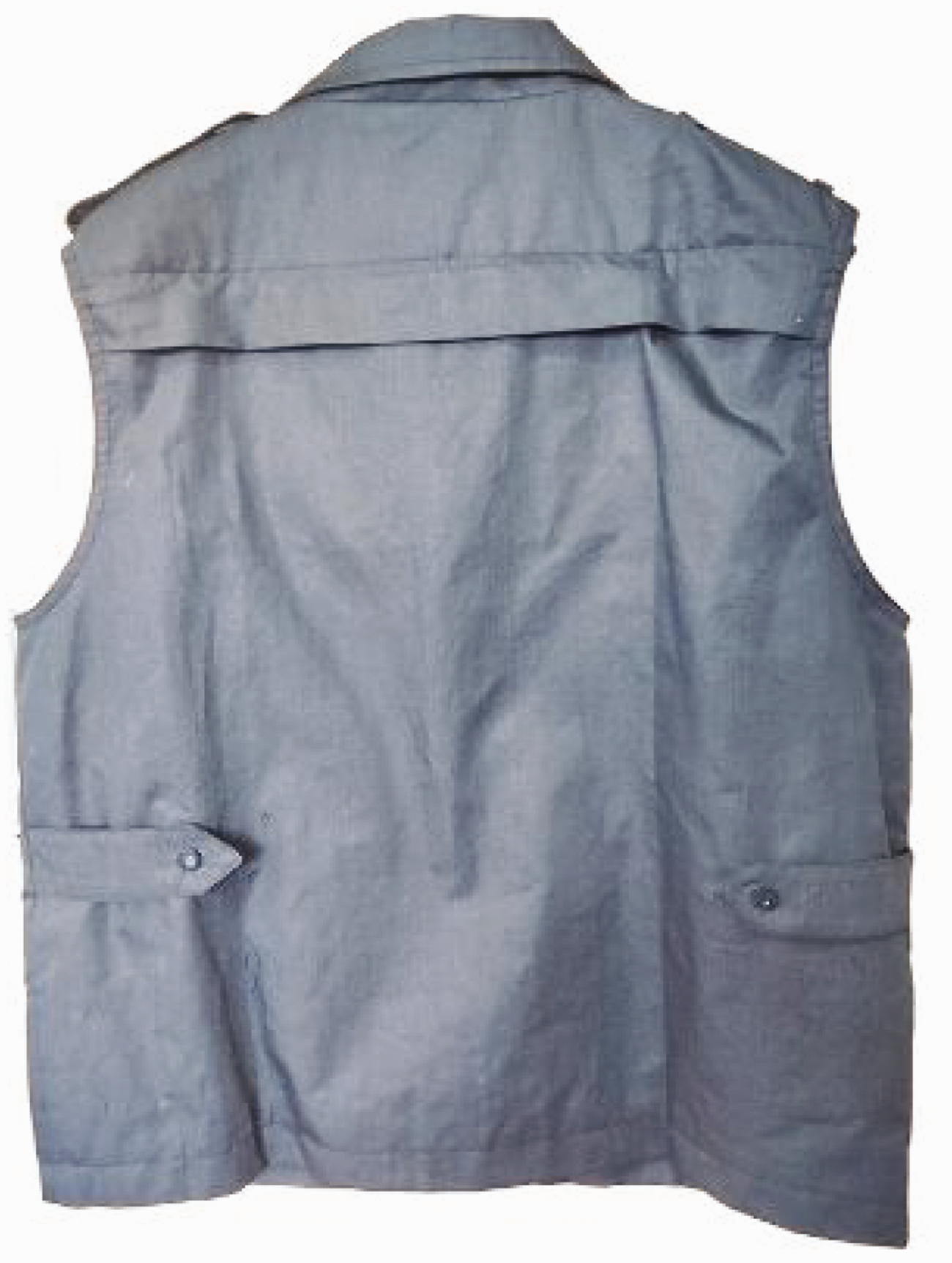
Figure 6 shows an EMS suit with a double-layered structure, the layers of which can be detached from each other using buttons. The anti-EM radiation shielding functional layer is made of anti-EM radiation shielding fabric produced by multi-target vacuum magnetron sputtering coating technology and composite coating anti-oxidation technology. This process significantly improves the product's binding, wear resistance, and corrosion resistance. The outer layer is made of high-count 60% cotton and 40% polyester fabric, with a soft and comfortable texture and light weight, and is breathable to wear. It provides 55 dB SE under the frequency range of 10 kHz–36 GHz and can protect the health of personnel who work for a long time in environments such as radar stations, microwave stations, communication stations, and ships.
Electromagnetic shielding suit.
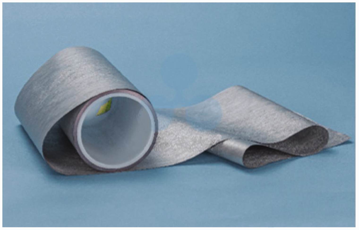
Figure 7 shows an EMS conductive fabric available on the market, which can be widely used in EMS, for anti-static and grounding, such as in electronic products like smartphones, wearable devices, liquid crystal display (LCD) monitors, automated high-frequency equipment, and medical instruments, as well as in the military and aerospace fields.
Electromagnetic shielding conductive fabric.
The product uses lightweight polyester triangular-shaped yarn (50d × 50d) and 36f yarn as the base cloth, and sequentially deposits Ni-Cu metal film layers by the vacuum deposition method, and then sequentially deposits Ni-Cu-Ni by the electroplating method to make a composite metal film layer with five layers of metal films. The product has good adhesion and curing properties of the metal film layer and high EMS performance.
Figure 8 shows a seamless knitted wire EMI gasket, which is commercially available and made by compressing a certain amount of seamless knitted wire mesh without joints or interfaces using molding. The product has good EMS performance, controllable density, good elasticity, low cost, and easy installation. The seamless knitted wire EMI gasket made of 0.127 mm diameter brass wire can achieve a shielding performance of 95 dB under MIL-STD-285 10 GHz wave test conditions. It is widely used in EMS applications such as cable TV, microwave ovens, waveguide flanges, connectors, and filter installations. It can also be used for shaft sealing, heat sinks, shock absorbers, and filters, and can be handcrafted and assembled according to prototype requirements.
Seamless knitted wire electromagnetic interference gasket.
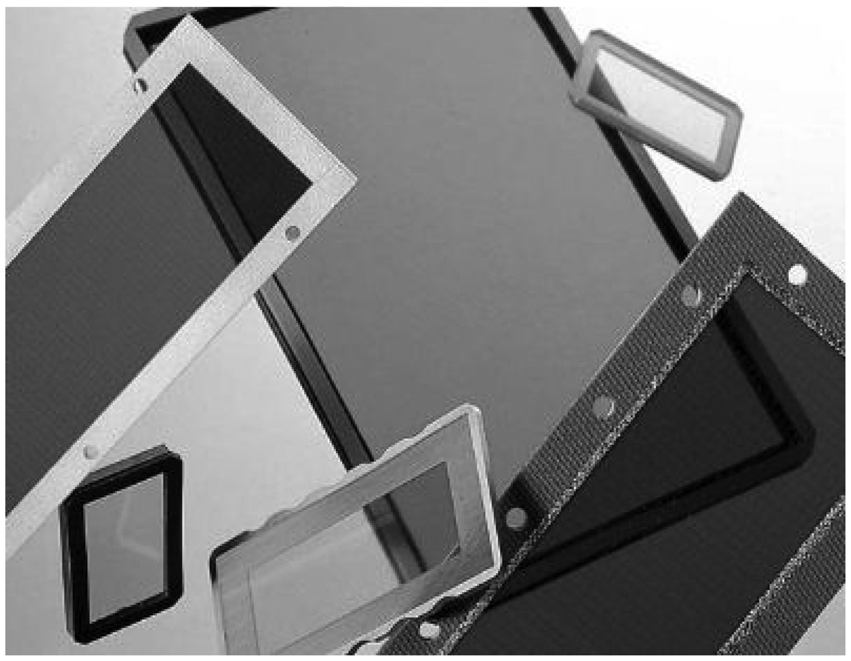
Figure 9 shows a commercially available high-performance EMC window, which is made by sandwiching a mesh screen made of 0.05 mm copper wire between two layers of glass or acrylic. It provides 60 dB SE under a 1 GHz plane wave and is suitable for device enclosures that require excellent EM radiation or sensitivity shielding. It can also provide maximum EMI protection and high optical clarity for electrostatic printers, digital displays, graphics, and other flat-panel displays.
High-performance EMC windows.
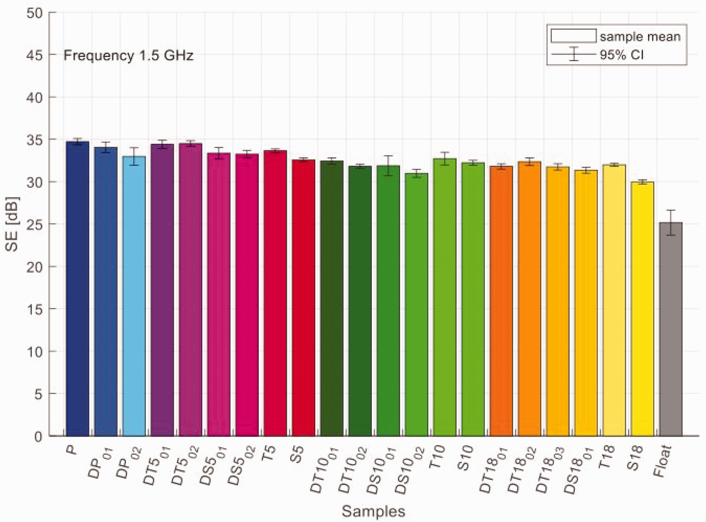
Electromagnetic shielding effectiveness (SE) [dB] of all experimental samples at 1500 MHz (P: plain weave; DP: derived plain weave; T: twill weave; DT: derived twill weave; S: satin weave; DS: derived satin weave). 70
Research status of electromagnetic shielding structure mechanism factors
Fabric-based EM materials are effective shielding materials that can block or attenuate EM radiation. 68 Compared to traditional EMS materials, the advantages of these materials include the following.
Lightweight and flexible: fabric-based EM materials are typically made of lightweight and flexible materials such as polyester, cotton, or nylon blended with metal fibers, making them easy to handle, cut, and install in a variety of applications.
Breathability: compared to other EMS materials such as metal foil or conductive paint, fabric-based EM materials typically have breathability, making them suitable for applications that require air circulation.
Washable: fabric-based EM materials can be washed multiple times and reused without affecting their SE.
Cost-effective: fabric-based EM materials are usually more cost-effective than other EMS materials, such as metal foil or conductive paint.
Versatile: fabric-based EM materials can be used in various applications, such as clothing, curtains, tents, and bags.
However, compared to other EMS materials, fabric-based EM materials also have some limitations. For example, under certain conditions, they may not provide as much SE as metal foil or conductive paint. In addition, they may not be suitable for applications that require high durability or resistance to harsh environments. Overall, the choice of EMS material depends on specific application requirements and constraints. In order to scientifically guide the research and development of such fabrics, researchers qualitatively studied the EMS mechanism of such fabrics from the aspects of metal content, fabric tightness, fabric structure, and fabric layers.
Influence of fabric structure on EM shielding performance
It is generally believed that in the case of the same fabric parameters, such as density, yarn density, and metal content, the SE of twill fabric is better than that of satin fabric, while the SE of plain fabric is better than that of twill fabric for basic fabric. 69
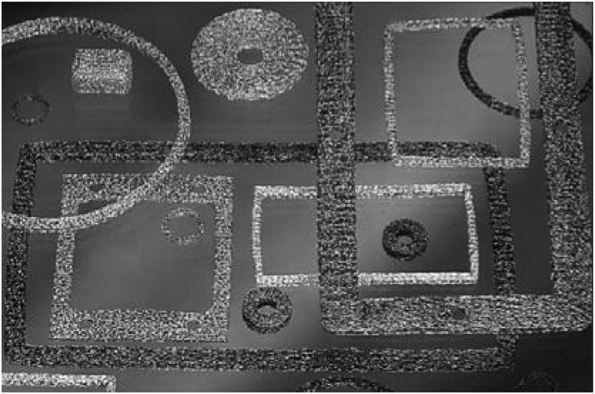
To analyze the weaving pattern of a special conductive fabric, Sirkova 70 conducted research on 21 different dobby weave fabrics production using input yarns composed of polyethylene terephthalate (PET) fibers and stainless steel fibers, as shown in Figure 10. The fabric’s SE was analyzed in the frequency range of 30–1500 MHz using coaxial transmission line technology. The results indicated that the plain weave fabric demonstrated the highest EMSE across the entire frequency range of the study. This phenomenon was expected due to the plain weave structure having the maximum cross-over unit frequency. The interlacing of the weft and warp threads in a coherent and stable structure facilitated an efficient EM radiation barrier.
Jiang et al. 71 used metal fiber blended yarn to weave five kinds of fabrics with different organizational structures and different warp and weft yarn configurations, tested the microwave radiation shielding performance of the fabrics, and analyzed the influence of metal fiber content and organizational structure on the microwave radiation shielding performance of the fabrics. The results showed that the organizational structure had certain influence on the shielding performance of the fabrics. When the content of stainless steel is the same, the shielding efficiency of the plain texture is the best, followed by twill, and satin is the worst. Because of the shortest floating length of the plain tissue, the most compact structure, and the fewest gaps and voids formed, the EMS efficiency is the best. However, because stainless steel fibers mainly rely on reflection to achieve EMS, there are differences in the EMS principle compared with other fibers. It remains to be studied whether different EMS fibers will affect each other or achieve the effect of 1 + 1 > 2 when blending.
Influence of fabric tightness on EM shielding performance
Xiao et al. 29 analyzed the structure of woven fabrics containing metal yarn and proposed that the effective EMS structure of such fabrics is composed of metal fiber yarn. After that, the mesh structure arranged samples were prepared with pure copper wires, and the model samples were changed by changing the arrangement mode, arrangement spacing, intersection, and surrounding connectivity. Shielding efficiency in the range of 1–18 GHz was obtained by the shielding chamber method. The results show that the spacing of metal yarn is the key factor affecting the shielding efficiency. 72 In the parallel samples with copper wire spacing of 1, 2, 3, 4, and 5 mm, the shielding efficiency of the sample with 1 mm spacing can reach 37 dB, which is much higher than that of the sample with 2 mm spacing (Figure 11). However, when the spacing is 4 or 5 mm, the shielding efficiency tends to 0. Therefore, the shielding efficiency increases with the spacing. The spacing of the metal yarn is an important factor affecting the shielding efficiency of the fabric, which is determined by its density or tightness. The optimal yarn density and the number of needles or coils per centimeter are also one of the important factors affecting the coverage coefficient and volume porosity. 73 The shielding efficiency of the unidirectional and bidirectional arrangement of metal yarns is the same, but the unidirectional arrangement of metal yarns has significant directionality. The mesh size of the bidirectional meshes affects the shielding efficiency. For the sample with parallel wires, whether the wires are connected around has little effect on the shielding efficiency, and the specific reason remains to be studied.
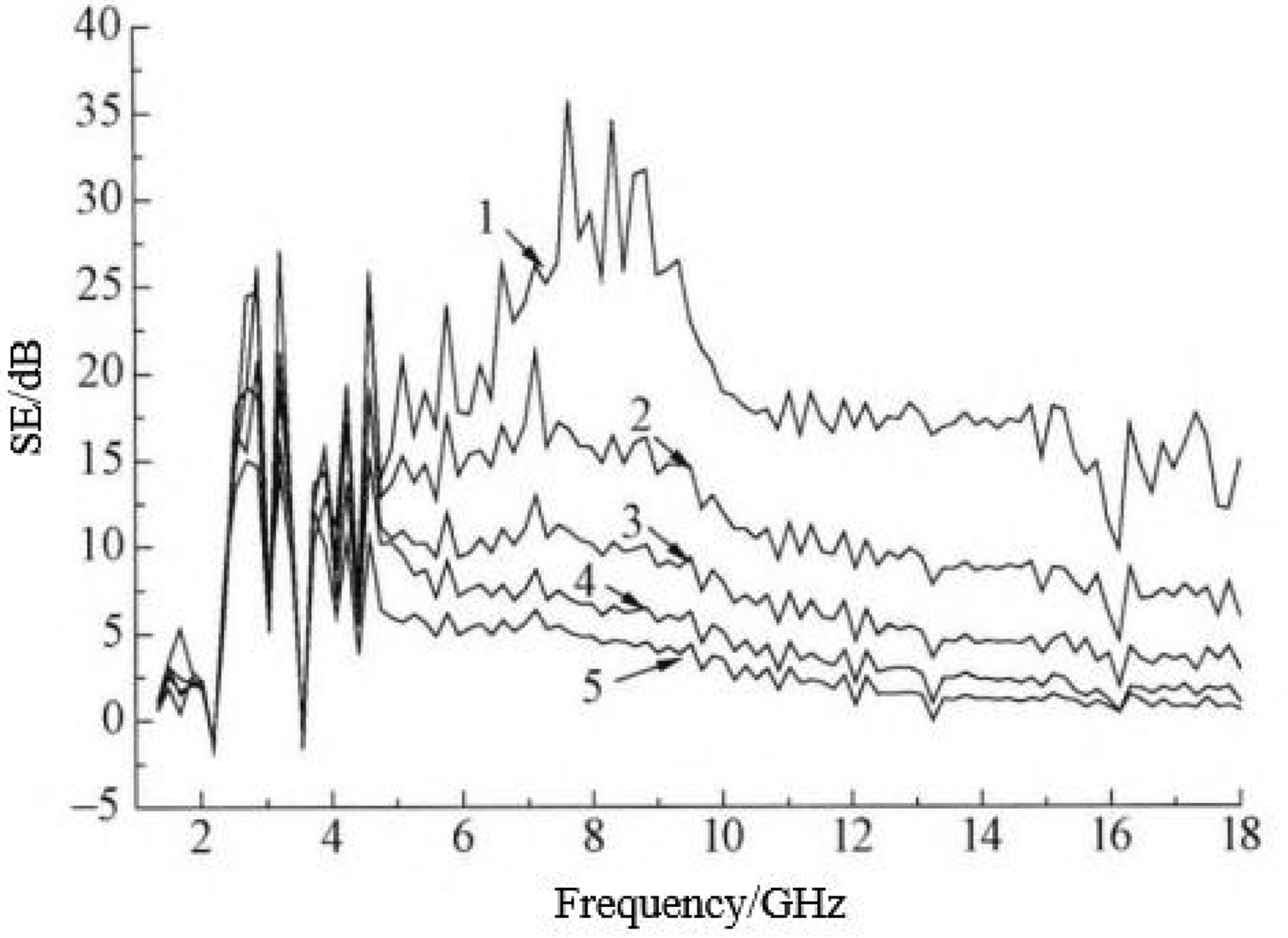
Shielding effectiveness (SE) of different arrangement spacings (1 corresponds to dw = 1 mm; 2 corresponds to dw = 2 mm; 3 corresponds to dw = 3 mm; 4 corresponds to dw = 4 mm; 5 corresponds to dw = 5 mm). 72
Liu and Wang 74 studied the relationship between fabric tightness and the SE of blended electromagnetic shielding fabric (BESF). The SE of the BESF with different tightness was tested using the waveguide test method. The experimental analysis shows that there is a positive correlation between the SE value of BESF and its tightness (Figure 12(a)). Under the conditions of the same metal fiber content, the same weaving type, and different yarn density, the SE value of the same tightness fabric is consistent (Figure 12(b)). Under the same tightness, metal fiber content, and yarn density, the SE values of different types of fabrics are not consistent (Figure 12(c)). According to the EM theory, the theory of the relationship between the SE of yarn and the tightness determined by the state of adjacent yarns is put forward, and some formulas for determining the tightness boundary are given, which can provide reference for the design, manufacture, and testing of BESF.
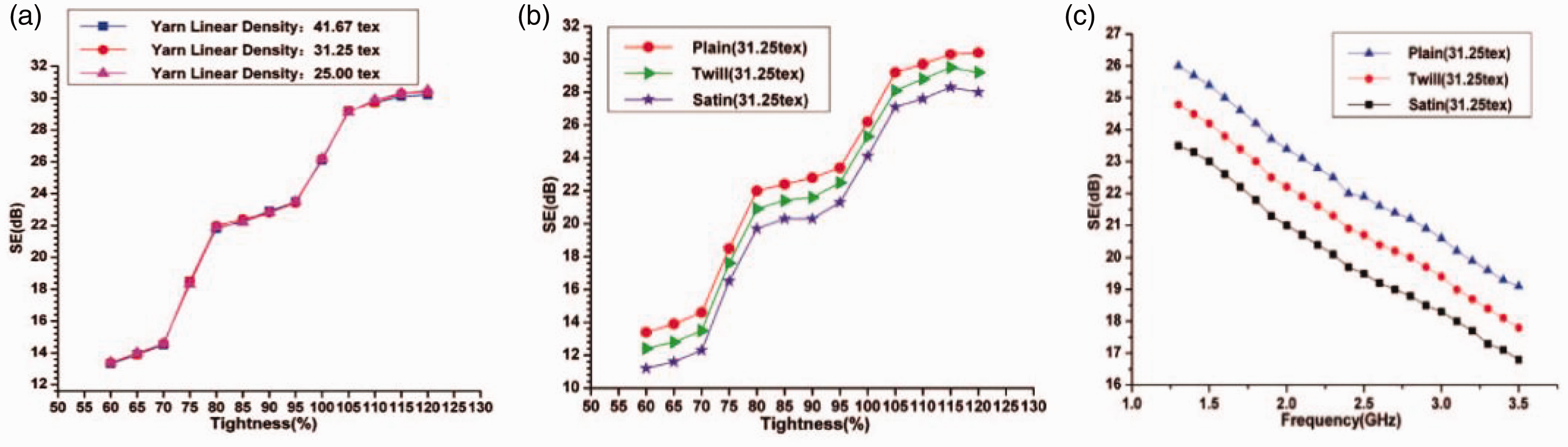
(a) Relation between the shielding effectiveness (SE) and the tightness of the samples. (b) Relation between the SE and the tightness of the different weave samples and (c) Influence of frequency on the SE of the same tightness samples in a frequency range (3–3.5 GHz; tightness: 80%). 74
Liu et al. 75 pointed out that the existing studies of EMS fabric density only proposed the density at which the SE of the fabric changes as it changes. However, they did not find and reveal a law whereby the SE is not affected by changes in meridional and zonal density when the total density is the same. This phenomenon has important guiding significance. When designing EMS fabrics, we only consider the index metal fiber content per unit area (MFCPUA), and do not pay attention to the specific values of warp density and weft density.
Effect of yarn type on EM shielding performance
In another experiment, Xiao et al. 76 changed the type of yarn and used different types of metal yarn and cotton fiber to prepare a grid structure arranged sample. The shielding performance and reflection coefficient of the sample were tested by the shielding chamber method and the arch method, respectively. The results show that the type of yarn has a significant effect on the shielding efficiency and reflection coefficient. Under the same fiber spacing, the shielding efficiency of pure stainless steel filament, core-wrapped yarn, and twisted yarn samples was similar, which was lower than that of stainless steel blended yarn samples with the mass fraction of 30%. For the reflection coefficient, the stainless steel blended yarn sample has the best reflection performance and the core yarn sample has the worst. However, the shielding efficiency of pure copper wire and copper wire core-wrapped yarn, which rely on conductivity to achieve EMS, has not been studied.
Marciniak et al. 77 conducted a study on a novel EMI shielding material, which is a woven fabric based on steel yarn/copper wire solenoids (Figure 13(c)). They successfully fabricated these solenoids as hybrid yarn by wrapping copper wire around steel yarn (Figure 13(a)). The results showed that for plain weave fabric woven with one hybrid yarn/three cotton yarns (Figure 13(b)), the highest EMI SE measured was 40 dB at 490 MHz.
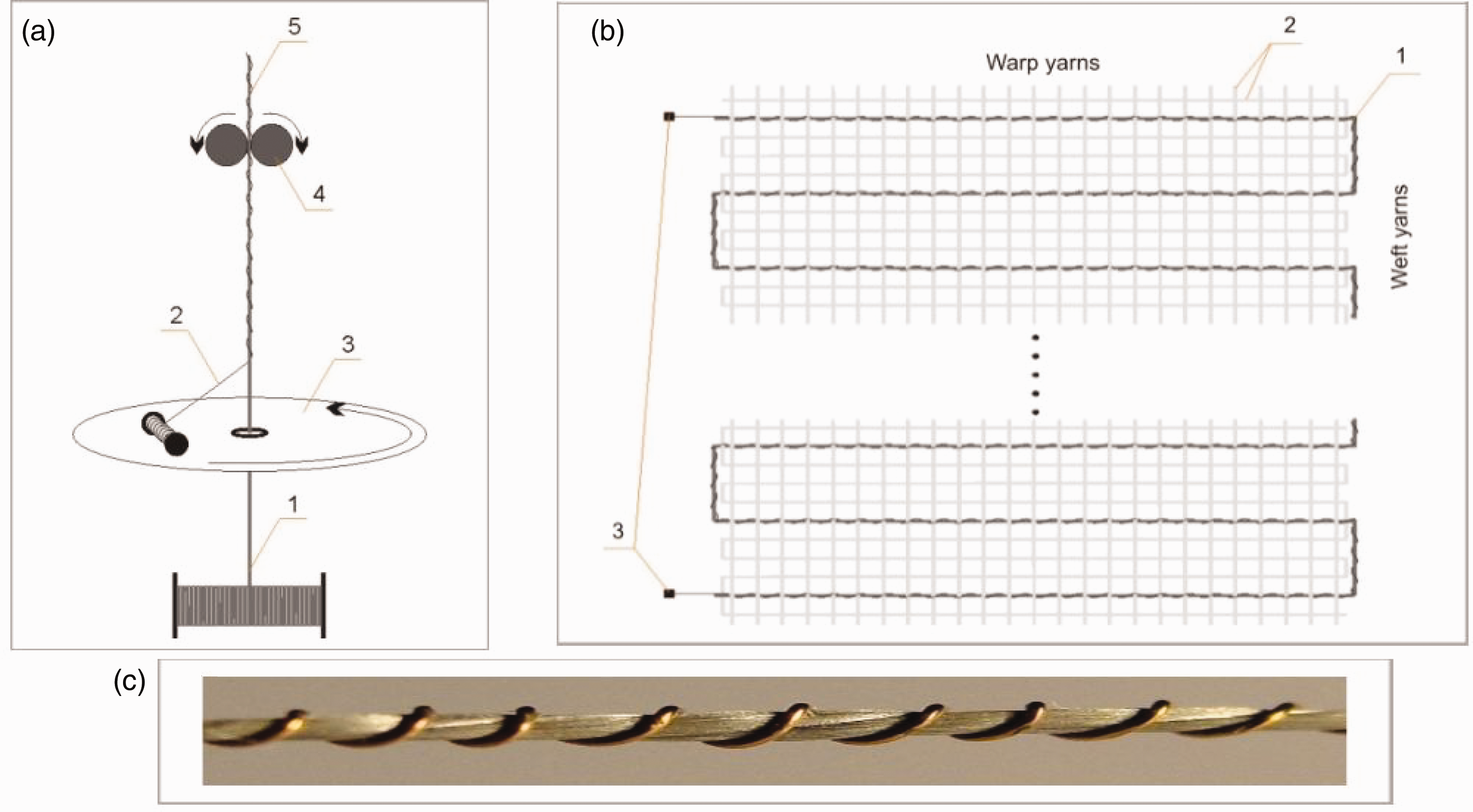
(a) Copper yarn braiding on steel yarn: 1 – Bekinox VN steel yarn, 2 – copper wire, 3 – rotating disc, 4 – rollers receiving the hybrid yarn, 5 – hybrid yarn. (b) Fabrication scheme of hybrid yarn based woven fabric: 1 – hybrid yarn, 2 – cotton yarns, 3 – copper wire ends and (c) Hybrid yarn: copper wire wrapped on a steel yarn. 77
Electromagnetic shielding efficacy (EMSE), absorption, and reflection graphs for stainless steel composite fabrics: (a) single layer and (b) double layer. 78
Liu et al. 42 selected 20 different spun fabrics in order to analyze the EMS performance of different spun fabrics. It is found that the EMS effect of composite yarn-woven fabric is better than that of blended yarn-woven fabric. It is speculated that in the blended yarn, the stainless steel in the staple fiber is random and discontinuous, which is not conducive to the conduction of EM waves in the fabric. However, the distribution of stainless steel in the filament is continuous, which is beneficial to improve the conductivity of EM waves in the fabric, the specific reason for which remains to be verified.
Influence of fabric layers on EM shielding performance
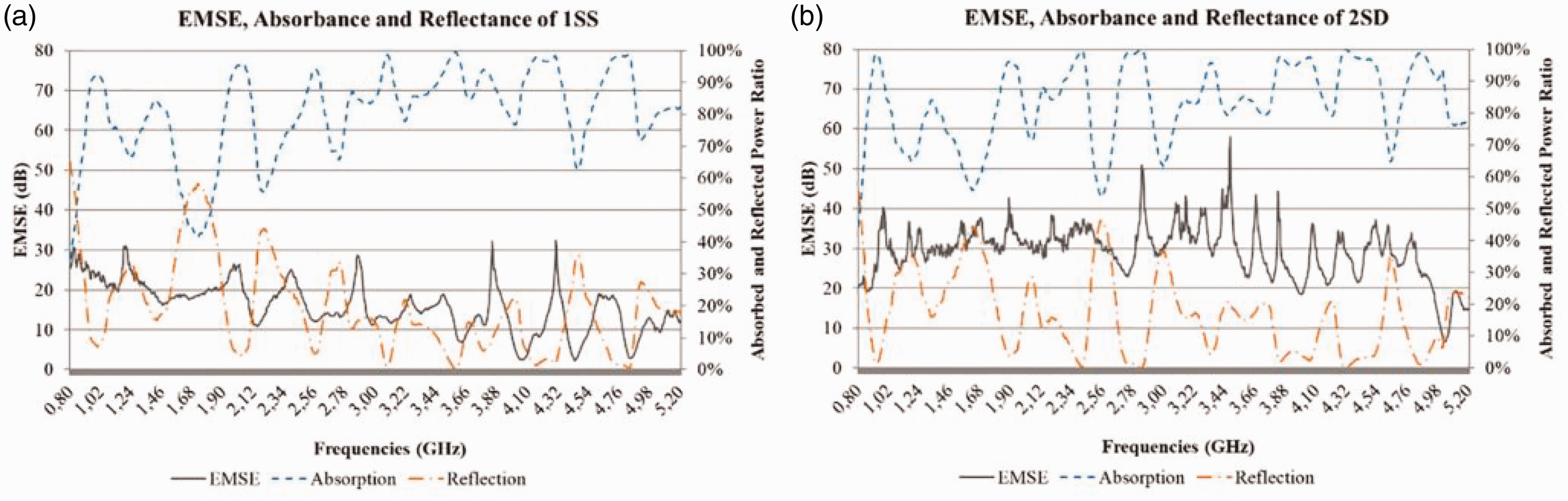
In the study of Ozkan et al., 78 stainless steel, copper, and silver wires were mixed with two polyamide 6.6 filaments by mixing technology to produce a three-component mixed yarn used as a sample for producing plain fabrics. The EMS efficiency parameters of the samples were measured in the frequency range of 0.8–5.2 GHz, as shown in Figure 14. The influence of fabric layers on the EMS and absorption and reflection performance of woven fabrics is statistically analyzed. The results show that the EMS efficiency values of the bilayer samples are higher than those of the monolayer fabric in both frequency ranges, and the increase in the density of the mixed yarn in the fabric structure leads to an increase in the EMS efficiency value. However, the number of layers has no significant effect on the absorbed and reflected power in the 0.8–2.6 GHz range. However, there is a significant difference in the absorbed power ratio above 2.6 GHz frequency, and the reason remains to be found.
Marciniak et al. 79 used a vector network analyzer and a coaxial transmission line tester to test the SE of fabric samples. Surface images of different fabric structures were studied to understand the effect of yarn float on the shielding behavior of the fabric. It was found that increasing the number of fabric layers also improved the SE of the fabric. The developed cotton/stainless steel/PP hybrid yarn fabric can be used for shielding wireless transmissions and radar transmissions, and shielding panels.
Katarzyna 80 studied the variations in EMS performance of woven fabrics (Table 3) made of cotton (warp and weft) and hybrid yarn (weft) by changing the number of layers and the overlapping angle. The study found that using two layers of shielding fabric with a hybrid yarn in parallel provides higher EMSE than a single layer for the resonance frequency and 30 MHz frequency. However, increasing the number of layers placed on top of each other at an angle of 0° to more than two does not provide a higher SE. Two layers of fabric placed one on top of another, with the hybrid strand introduced as the thread in one layer having the opposite lay to the lay of the hybrid strand in the other layer, provide a higher SE than two layers of fabric placed parallel on top of each other, but only for the resonance frequency. Increasing the number of layers of fabric aligned at an angle of 45° provides a higher SE only for a frequency of 30 MHz.
In Ozkan and Telli's experiment, 78 with the addition of a second layer of fabric, three shielding mechanisms appeared in the fabric structure. In the first mechanism, waves passing through the first layer are absorbed by the second layer. In the second mechanism, part of the wave reflected from the second layer is absorbed by the first layer. In the third mechanism, repeated reflections occur between the first and second layers, and most of these waves are absorbed and converted to heat. These three mechanisms and reciprocal interference effects support the absorption ratio of EMSE. Further studies are needed to better understand the EMSE, absorption, and reflection behavior of multilayer composite fabrics.
Study on the structure model of electromagnetic shielding fabric
In recent years, much research has been conducted on the shielding efficiency calculation model of EMSF.
Perforated metal sheet model
Some researchers consider EMSFs as perforated metal plates and use the formula for calculating the SE of perforated metal plates to estimate the SE of shielding fabrics. The premise for using this model is that the entire fabric has good electrical connectivity, with a resistance comparable to that of the metal plate, the fabric has a certain thickness, and the pores in the fabric are regular.
Henn and Cribb
81
provided a SE formula for metalized fabrics against plane waves. The SE of metalized fabrics is related to the geometrical structure of the fabric, such as pore size, thickness, and surface resistivity of the material. When the wavelength of the incident EM wave is much larger than the pore size of the fabric, the metalized fabric will reflect the EM wave like a metal foil. As the frequency increases, the ratio of the pore size to the wavelength gradually increases, and the impact of pores on the SE becomes prominent. Therefore, Henn and Cribb considered metalized fabrics as a weighted combination of metal foils and perforated metal plates, with a weight function 


In the equations,
Safarova et al. 82 used the same method mentioned above to calculate the SE of tightly knitted metal fiber blended fabrics. Both the SE of a solid metal plate and the SE of pores were considered, and the weights of the two were combined as the theoretical calculation formula for the SE of the fabric. Since the type of fabric under consideration was different, the weight function was different from that in Henn and Cribb. 81 The authors also used image processing techniques to analyze the pore morphology in the fabric. Irregular pores were approximated as rectangular pores, and linear regression equations between the SE and EM parameters of the fabric were established by statistical analysis. Based on Equations (6)–(8), the SE of the metal fiber blended fabric could be obtained given the pore size, fabric thickness, and volume resistivity of the fabric. The calculated results were in good agreement with the measured results up to 3 GHz. However, image processing techniques can only obtain the pore size between metal-blended yarns, and the consistency between the effective diameter of the blended yarns and the pure metal fiber yarns remains to be proven. Figure 15 shows a diagram of the pore model in the fabric.
Opening of fabric.
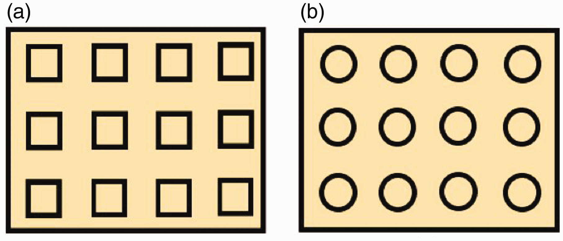
Liu 83 used a pore model to equivalently represent metal-coated fabrics, considering the holes in coated woven fabrics to be square, as shown in Figure 15(a), and the holes in coated knitted fabrics to be circular, as shown in Figure 15(b). The SE calculated using this model was in good agreement with the SE obtained from the SN/T 2161-2008 “Microwave performance test method for textile products – waveguide method.” However, there are still shortcomings in this model, as it requires the coating to have good conductivity and the hole size to be the same or approximately the same, which is an idealized situation. In addition, the model's application conditions require that the diameter of the circular hole or the side length of the rectangular hole be much smaller than the wavelength of the incident wave.
Metal wire grid structural model
This structural model is currently one of the models that is more in line with the real effective shielding structure of fabrics, and its shielding characteristics are mainly due to the reflection of EM waves on its surface. 84
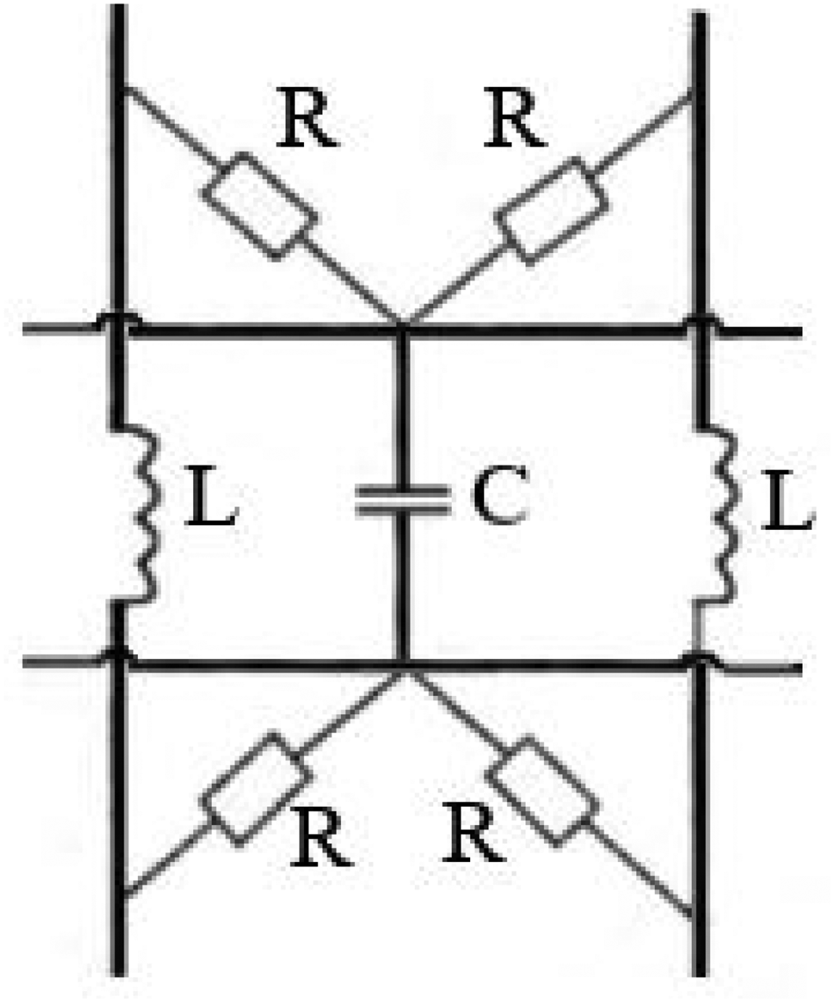
Xiao et al. 85 studied the equivalent circuit of EMSF, and according to the structural characteristics of fabric formed by the warp and weft yarns, the period unit of EMSF can be equivalent to the equivalent circuit shown in Figure 16.
Equivalent circuit of electromagnetic shielding fabric. 85
In this figure, the inductance L comes from the spiral structure formed by the twisted metal fibers of the yarn, the capacitor C comes from the parallel metal fibers, and the resistance R comes from the contact resistance of the warp and weft yarns at the intersection. It is found that the main factors affecting the EMS effect of metal fabric are the spacing of the metal fiber yarn and the weaving mode, the passing probability at the intersection of metal yarns and types of metal yarn. This study solves the lack of general parameter extraction in the previous qualitative research, and has scientific and engineering significance to guide the development of EMSF, and has universal significance. The establishment of the equivalent circuit and the specific parameters extracted from it lay a foundation for the quantitative numerical calculation of shielding efficiency, and have far-reaching guiding significance for future research.
Chen et al.
86
produced conductive woven fabrics by twisting and covering copper wire, stainless steel wire, and PP yarn, which were equivalent to metal mesh structures. They assumed that a single mesh was rectangular, the metal fibers had good conductivity, and the intersections of the metal mesh had good contact. They used Equation (9) to evaluate the SE of the fabric and measured the SE of a single-layer fabric using the coaxial transmission line method. However, the difference between the measured values and the calculated values was large, about 50 dB, for frequencies from 30 MHz to 1.5 GHz. This may be because the yarns in this structure caused poor contact at the intersections in the actual fabric. Meanwhile, He and Yi
87
used Equation (9) to calculate that the SE of a knitted fabric made of 3.9 tex stainless steel wire could reach 14–36 dB in the frequency range of 10–3000 MHz when the distance between adjacent steel wires was 0.1–0.25 mm:

In the equation, Aa represents the absorption loss of the hole; Ra represents the reflection loss of the hole; Ba represents the multiple reflection correction factor; K1 represents the correction factor for the number of mesh holes per unit area; K2 represents the correction coefficient for low-frequency penetration; and K3 represents the correction coefficient for mutual coupling between adjacent mesh holes.
The equivalent circuit model of a periodic structure was initially proposed by Anderson. 88 Rybicki et al. 89 further proposed an equidistant planar mesh structure composed of a conductive yarn, in which the unit shape was square, the intersection points were in close contact, and the thickness was negligible. They established an equivalent circuit model for the conductive yarn mesh structure, including inductance L, capacitance C, and contact resistance R, and pointed out that the equivalent impedance of the metal mesh depends on the polarization mode of the incident EM wave. Cai et al. 90 used the metal mesh model in Casey 91 to calculate the SE of blended fabrics with stainless steel fiber contents of 5%, 10%, and 15%, and performed experimental tests using the flange coaxial method. The simulation results were consistent with the experimental results in the frequency range from 300 kHz to 1.5 GHz, especially in the low-frequency range of this frequency band.
Li et al. 92 discussed the principle of EMS of metal fabrics using Equation (9). They established a three-dimensional simulation model containing stainless steel long filament woven fabric using the multiphysics field-coupled analysis software COMSOL Multiphysics, and analyzed the factors that affect the SE of the fabric. The model assumed that the metal mesh was made up of infinitely long metal wires, had a fixed mesh spacing, and had zero contact resistance at each node. The grid division used in their calculation is shown in Figure 17. This software can directly define the global EMSE value. The transmission power Pt, reflection power Pf, and absorption loss PQ were calculated by integrating the total field energy flow at the output end of the model, the scattered field energy flow at the input end, and the EM power loss density of the stainless steel wire, respectively. The simulation results were good within 3 GHz.
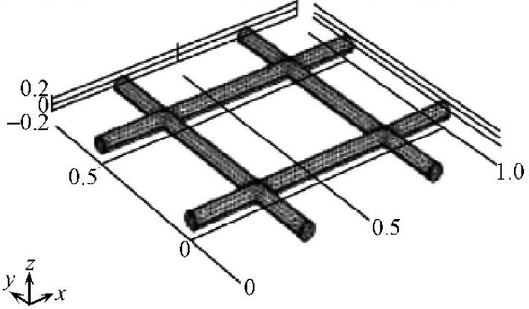
Mesh division of stainless steel wire. 92
The plain weave structure.
Structure of wire mesh.
Liu et al. 93 proposed a partition method based on the yarn diameter and fabric structure. According to the characteristics of the fabric structure, it can be divided into an overlapping area, transverse single yarn area, longitudinal single yarn area, and gap area. The fabric structure model based on SE finite-difference time-domain (FDTD) numerical calculation is constructed. The EM parameters of each region were tested according to the transmission and reflection method, and the Yee grid discretization method of the structural model was given. The physical model of the fabric was determined by setting the absorption boundary and the excitation parameters. In the model, the overlapping region is the center of the encircle of the transverse single yarn region, the longitudinal single yarn region, and the longitudinal single yarn region. Each region type is considered to be an ideal uniform medium with regular dimensions and the same EM parameters. The numerical calculation of the physical model is completed by East FDTD EM calculation software. The calculated data are compared with the actual test data. The results show that the proposed model is satisfactory for the SE calculation results of EMS fibers. The research of this paper provides important reference values for the design, production, evaluation, and theoretical research of EMS fibers.
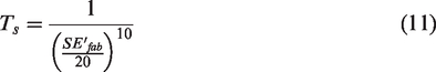
According to EMS theory, Wang and Liu
94
set the hole area as S, the short side as a, the long side as b, and the total area as A for the rectangular hole on EMSF with holes, and established the theoretical calculation model of EMSF SE with holes:
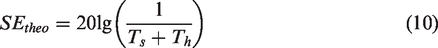
The transmission coefficient Ts of the fabric and the transmission coefficient Th of the hole are calculated as follows:
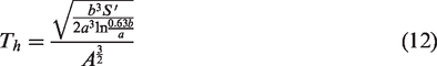
After fitting the theoretical values with the measured values of several groups of samples, the equivalent coefficient 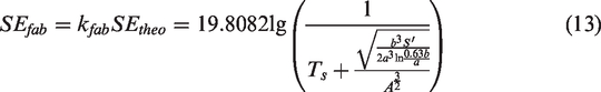
Through this calculation model, it is not necessary to know fabric parameters such as fabric density, yarn tightness, and yarn diameter in advance. 95 The experimental results show that the fast calculation model based on the equivalent coefficient has a good effect on the SE of EMSF with plain, twill, and satin. The factors of fabric density and metal fiber content have no significant effect on the calculation results of the model. At the same time, the conversion coefficients of SE calculation for plain, twill, and satin fabrics were determined through experiments, and a fast SE calculation method based on the virtual metal model was established. 96
Other numerical calculations
There are many studies that use EM simulation software to estimate the SE of EMSFs, metal meshes, or metal plates. Liu et al. 97 digitized the surface of EMSFs through computer image analysis, identified metal fibers on the surface of EMSFs according to edge conditions, width conditions, and gray conditions, and proposed that the coverage, dispersion, and uniformity of metal fibers on the surface could describe the surface metal fiber (SMF) percentage content, porosity, and orientation of EMSFs. They were positively, negatively, and positively correlated with the SE of EMSF, respectively. This experiment opens up a new idea for the study of the relationship between the surface metal fiber arrangement and SE, and is of great significance for further study of the shielding mechanism, absorbing mechanism, EM transmission characteristics, numerical calculation, and rapid nondestructive evaluation of SE in EMSF.
Greco et al. 98 reported on a material modeling tool (MMT) that can simulate the SE of non-homogeneous materials, such as metal meshes, metal thin films, and single-layer or double-layer woven fabrics, based on the geometric structure and electrical properties of the fabric. The model assumes that the incident field is divided into transverse electric waves and transverse magnetic waves, and that conductive fabrics can be simulated as sandwich structures or metalized mesh structures depending on the weaving method and metallization type. When the fabric structure is dense, and there are no pores after coating, it is simulated as a sandwich structure with metal/fabric/metal layers. When the fabric structure is not dense, it is simulated as a rectangular metal mesh. The simulation results are in good agreement with the results obtained from the coaxial waveguide method for frequencies up to 18 GHz.
Zdeněk et al. 99 conducted a numerical analysis of the EMSE of a rectangular aperture structure model. They established a high-frequency numerical model using integration characteristics, and applied partial differential equations, high-order finite element methods, and COMSOL Multiphysics (a software for coupled multiphysics analysis) in the simulation. The theoretical values obtained through integration were in good agreement with the results from the shielded room test for frequencies up to 2.5 GHz. Meanwhile, Miron et al. 100 presented a numerical simulation model for predicting and analyzing the EMS performance at high frequencies.
Due to the long sample preparation process, long testing cycle, and high testing cost required to evaluate the design quality of EMSF, Liang et al.
101
established a general equivalent model related to the shielding factors TMz and TEz of polarized waves:
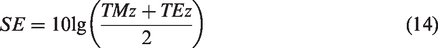
This method can be used to estimate the SE of fabric. This method has the advantages of simple operation, convenient operation, and high precision, and has high application value for the design and development of metal fiber yarn fabric. It is helpful to the design and development of EMSF to some extent. In addition, it also has a certain guiding effect on the design of fabric structure parameters and the selection of materials.
The prospect of plain electromagnetic shielding fabric
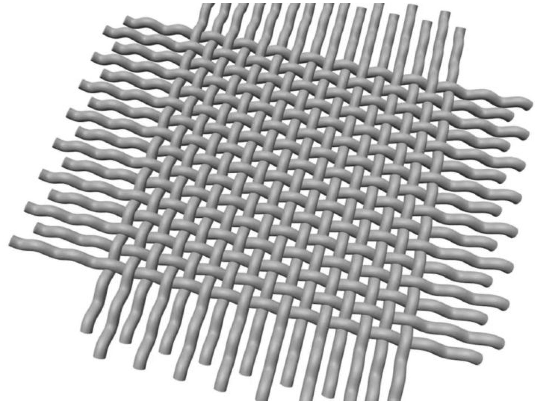
The structure of metal mesh is similar to that of plain weave fabric, as shown in Figure 18. According to the research of Abdullah and Yuksel, 102 the analytical method of metal mesh can be used to analyze the EMS performance of plain weave fabric. Zhang et al. 103 found in their research on the application of metal grid EMS film on infrared air-to-air missiles that there are three parameters affecting the optical transmittance and EMS performance of the metal grid: the thickness of metal grid, the width of metal wire, and the interval period between two adjacent metal wires.
EMS grids are very popular to block unwanted EM radiation from circuits/systems. For this purpose, grids consisting of metals, metal alloys, and conductive materials have been widely used in the past few decades.
104
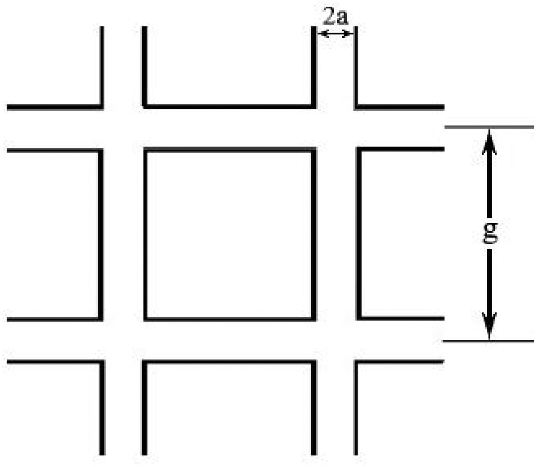
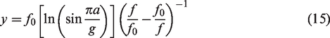
Ulrich
105
analyzed the EMS effect of a metal grid, as shown in Figure 19. When the thickness t of the metal grid is far less than the linear width 2a, and the linear width 2a is far less than the linear period g, for the shielding effect of the vertically incident radar wave, the metal grid has the following normalization formula:
Chen 106 studied the transmission characteristics of microwaves for conductive metal plates with circular or rectangular holes of a certain thickness. Empirical formulas for the reflectance and transmittance coefficients of metal grid plates were provided, and a formula for calculating EM leakage was derived. The theoretical calculations are consistent with the experimental results, yet remain complex. Lee et al. 107 proposed formulas for calculating the transmission characteristics of periodic metal grid plates with zero or a certain thickness, which integrate the advantages of Chen106 and Ulrich's105 formulas but have some limitations. These formulas are only applicable to cases where the planar waves are vertically incident on the metal grid and the size of the unit grid is smaller than the wavelength of the incident wave. Casey 91 assumed that the metallic grid connections and shapes were rectangular and that the individual grid sizes were less than the wavelength of the plane wave. By analyzing the equivalent plate impedance of the metallic grid, a calculation formula for the SE of the plane metallic grid under different polarization modes was derived, which is independent of the polarization mode.
Wang et al. 108 studied the application range of the analytical formula for the SE of metal mesh on plane waves, and then studied the shielding mechanism of metal mesh on this basis. Based on the transmission line theory and the surface impedance formula of the metal mesh, an analytical model of the shielding efficiency of the double-layer metal mesh under the plane wave irradiation is proposed. The effectiveness of the model is verified by comparison with the full-wave simulation results, and the shielding characteristics of the double-layer metal mesh are further studied. The conclusion is as follows: when the direction of the electric field of the incident plane wave is parallel to the direction of the metal wire, the shielding efficiency of the metal mesh is the maximum. When the frequency is low, the value of the equivalent resistance and the equivalent inductance of the metal mesh can affect the shielding efficiency, but when the frequency is high, the value of the equivalent inductance can affect the shielding efficiency. Double-layer metal mesh may not provide better shielding than single-layer mesh when the mesh density is twice as much, but when the distance between layers exceeds a specific value, double-layer mesh can have a higher shielding efficiency that increases with distance. The specific values still need to be further studied and determined.
Shi et al. 109 designed and produced a kind of broad-spectrum high-permeability copper network, which can effectively shield EM waves. Copper mesh can be easily fabricated using mask photolithography and chemical etching. The thickness of the copper mesh is uniform, both in the cross-section and in the copper wire. The average transmittance of the copper network from the ultraviolet band to the near-infrared band (200–2500 nm) is 96%. Ku-band EMS efficiency is up to 16 dB.
To sum up, compared with EMSF, EMS copper mesh is more regular, there is no intersection point of the yarn, and it can achieve high transmittance. However, it also has its disadvantages, such as the production process is more complex, the cost is high, it is not suitable for high-speed mass production, and compared with pure metal yarn, its EMS efficiency is not obvious, so with the use of today's output of ultra-fine copper wire, woven copper net can in theory can be quickly mass produced with no less EMS efficiency and high transmittance than the traditional etched copper net.
Conclusion
EMS fiber-structural materials are gradually attracting the attention of researchers and the military because of their lightness, simple manufacture, rich material types, excellent EMS performance, and extremely wide application area. However, there are still some problems in the development of EMSF due to the difference in the previous development focus. Overall, it is mainly reflected in the following aspects.
Most stainless steel fibers are used in EMS fiber fabric, with which it is easy to produce a great deal of EM pollution in use. The understanding of fiber EMSF is limited to the wearing areas, and most of them are blended EMSFs. The research and application of pure metal fiber EMSF for industrial and military applications are few and generally not suitable for high-end industry. In the process of exploring the factors affecting the EMS performance of fiber-class EMSF, most of the rules are summarized based on the experimental results, without a systematic formulaic theoretical explanation, which is not conducive to the improvement of future products.
However, now, from the development status of fiber EMSF, it can be seen that the current EMSF research is using computer technology to a new level. Researchers can explore the influencing factors of EMS through equivalent circuits and other physical calculation models to develop fabrics with better shielding performance. Therefore, fiber EMSF can be started from the following aspects.
Increase the use of carbon fiber or microfine metal fiber to achieve a better EMS effect, and constantly try new materials in the application of EMSF. Strengthen the research on the mechanism of fiber EMSF. Further research should be carried out on the existing basis, and the physical structure model can be built from multiple angles with a full combination of computer technology, so as to more accurately describe the influencing factors of shielding, and to develop a shielding fabric with better performance. Not limited to the use of EMSF, explore the application of industrial EMSF, from low-end to high-end products. It is an eternal theme to combine high-performance EMSF prepared in the laboratory with industrialization and commercialization.
Footnotes
Declaration of conflicting interests
The author(s) declared no potential conflicts of interest with respect to the research, authorship, and/or publication of this article.
Funding
The author(s) received no financial support for the research, authorship, and/or publication of this article.