
Abstract
E-Textiles have gained enormous attention due to their specific characteristics in various non-conventional applications such as electromagnetic shielding materials. With the advent of various high frequency-driven devices, the need to restrict the non-ionizing radiations from their undesired effects became imperative. Due to the ease of production, better electrical conductivity and durability, the conductive hybrid cover yarns with continuous metallic filaments have earned its place as the most convenient form of yarns to develop E-textiles. However, controlling the amount of conducting material in yarns poses a challenge as the increase in size of the metallic filaments are associated with reduced electromagnetic shielding effectiveness due to increased stiffness of yarns, which resists in proper interlacement and hence causes openness in fabrics. The proposed design of conductive hybrid cover yarns is proven to have better tensile properties and modulus, therefore this design is more suitable to produced fabrics with higher cover factors. The amount of conducting material in the proposed design increased significantly without changing the size of the continuous filaments. Moreover, 99.9% shielding effectiveness is achieved with this increased metal content in fabrics in S-band and partly C-band microwave frequencies.
Keywords
Introduction
The electrosmog or the electromagnetic (EM) radiation is considered as a major environmental pollutant and has been under debate for quite some time. According to NASA [1], all EM radiations are light waves, but our eyes are only tuned to see the visible light spectrum, that is, 400 ƞm–700 ƞm. If only we could see beyond our limitations, the environment (both indoors and outdoors) would be flooded with uniform light from every direction.
The EM spectrum, its sources and impacts were studied vigorously by researchers during the past few decades, and the health hazards associated with short/prolonged exposures to the ionizing/ non-ionizing waves are of prime concern to many. The increasing severity of the problem is directly attributed to the intentional propagation of non-ionizing radiations for information technology sector, and the enormously increasing use of electronic/electrical appliances/vehicles and their unintentional propagation of EM waves from everyday use. With current technologies, which operates at 60 Ghz frequency band such as WiGig and collision prevention radars for vehicles, there is a 1000 times increase in electrosmog frequencies and photon energy since the 1950s [2]. Moreover, the need to shift the bandwidths to much higher frequency levels upon further advancements/requirements in these technologies is inevitable.
Apart from the EM interference phenomenon associated with EM waves, the prolonged exposure to non-ionizing radiations also affects the biological functions [2], heart and the autonomic nervous systems [3], ecosystem [4] and all the natural habitats in general [5]. In short, there is a dire need to restrict the undesired/unhealthy emissions and constant exposures by providing adequate shielding against the non-ionizing EM waves.
Textiles as protective shields
Conductive textiles have gained importance as efficient shielding materials due to their superior flexibility, pliability, porosity, low cost and ease of production, when compared to conventional shields made from metallic sheets [6]. Textile materials can be converted to EM shields by either giving them surface treatments like conductive paints, ionic/electroless plating or vacuum metallization. These textile materials can also be converted by incorporating conductive fillers inside in a particular order [7]. However, there are limitations attached to each process, for instance, intrinsically conductive polymers (ICP) have poor long-term stability, washing fastness and rigid characteristics that limits its application [8]. Carbon fibers coating is reported to have very high cost of production, while usage of carbon nano tubes is limited due to its cost, non-uniformity and dispersability, particularly for the multi-walled carbon nano tubes [9].
Although it has its own demerits but producing fabric by incorporating hybrid yarns with conductive fillers is a very popular, efficient and common way of producing EM shielding fabrics. These conductive fillers can be used in form of continuous filaments like metallic wires [10–12], or in the form of cut staple fibers [13]. The discontinuous metallic fibers in the later method reduce the electrical conductivity of the ultimate yarns and fabrics; moreover, the irregular placement of metallic fibers in the yarn structure develops less/more conductive zones in the fabrics.
The EM shielding effectiveness is measured in decibels (dB), it is the difference of intensity before and after the placement of shielding material in an EM shielding tester and is defined as [14]

where
P1 = Power received without sample.
P2 = Power received with sample.
A maximum of 42.2 dB electromagnetic shielding effectiveness (EMSE) is reported by Cheng et al. [15] at 2100 MHz when using a 30/70 stainless steel and polyester yarn and twill fabric with density of 238.5 g/m2. Perumalraj and Dasaradan [16] succeeded in achieving 74 dB in the frequency range of 800–1000 MHz using three-ply cotton copper yarn and twill weave with cover factor 17.4. Afa Ova and Militky [13] managed to achieve 35.98 dB at 1500 MHz by using 20/80 stainless steel/ meta-aramid yarn and 1/1 plain weave. Similarly, Ortlek et al. [17] reported a maximum of 49.94 dB at 284 MHz when using a pique (weft knit) fabric made with stainless steel core yarn. His other study [18] resulted in a maximum of 65 dB at 330 MHz using stainless steel/polyester yarn and 2/2 Rib fabric with density of 118 g/m2. Su and Chern [19] managed to achieve around 50 dB at 1800 MHz using 1/1 plain weave with fabric weight of 250 g/m2 while using stainless steel filament as conductive material. Similarly, Duran and Kadoglu [20] achieved maximum shielding of 48 dB on 200 MHz using silver-coated polyamide and cotton yarn in 3/1 twill weave structure. In another study, Cheng et al. [21] reported to have achieved 69.04 dB at 1800 MHz with four layers of 3/1 twill fabric made from 0.125-mm copper filament in core and cotton as wrap.
The research data above, to check the effectiveness of an EM shielding fabric, reveals the frequency range where significant amount of shielding is achieved (mostly with multiple layered shielding fabrics). Almost all the researchers concluded that as the frequency of incident EM wave increases, the shielding effectiveness first increases up to a certain level and after that threshold point it starts declining, reasons being the smaller wavelengths of high frequency waves and fabric openness.
Conductive hybrid cover yarns and its implications
The use of continuous metal filament to produce hybrid yarns for conductive fabrics stands out to be more efficient as far as the electrical conductivity is concerned. However, the metallic wires are rigid, less resilient and poor in terms of tensile properties when compared to the counter textile component. When these wires are placed inside the hybrid yarn as core component (in case of multicomponent plied, core sheath or covered yarns), the mechanical/tensile properties of these metallic filaments supersede the properties of the textile component [22]. Another adverse effect of the rigid wires is the reduced bendability while interlacing in fabrics. The stiffness of hybrid yarns with metallic core produces fabrics with enlarged interstices between warp and weft threads, hence making them transparent for high frequency waves [21]. Moreover, the transparency towards smaller wavelength waves further increases upon increasing the diameter of the wire (increased openness), in order to increase the amount of conducting material inside the fabrics to enhance the EMSE [16].
The declining tensile properties of metallic core hybrid yarns have been studied, and an alternate alignment for incorporating metallic wire as a covering component in hybrid yarn structures has been proposed [23]. It has been reported that the mechanical properties such as tenacity, initial modulus and elongation of the yarn improved multiple times by incorporating the conductive filament as covering component while keeping the textile material as the core component in the hybrid yarns structure [23]. This study therefore analyzes the impacts of this alternate alignment of metallic component on the electrical properties and EMSE of the conductive fabrics; furthermore, the impacts of alignment on the amount of conductive material in fabrics are studied.
Experimental methods
Materials
Due to its superior conductivity and resilience properties, copper filament was selected as the conductive component for this study. Three genres of copper with respect to its size including 0.14 mm, 0.11 mm and 0.08 mm were acquired from the open market manufactured by FE Magnet Wire (M) Sdn Bhd. For the counter textile component, 31 Tex polyester yarn was selected due to its ease of processability during yarn and fabric manufacturing.
Conductive hybrid cover yarn (HCY) preparation
Two component HCYs were prepared using the hollow spindle spinning technique on YCHN-303 Fancy Twister (Figure 1). The two components include the core and the covering component. The core component was channeled through the effect yarn assembly into the hollow spindle in presence of a tension draft. The covering component was wrapped on the core by the difference of rotation provided by the hollow spindle. The machine parameters were carefully monitored and controlled, as it has considerable influence on the output. These parameters include the hollow spindle speed, tension of core component and machine throughput for controlling and varying the number of turns of covering.
Hollow spindle spinning machine.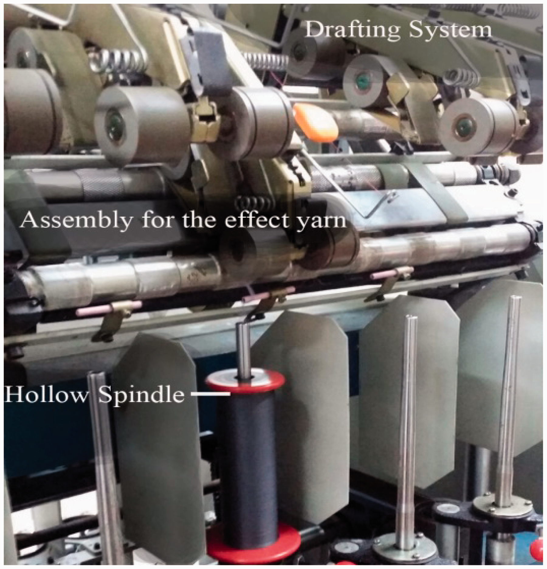
HCY Classification.

HCY: hybrid cover yarns; TPM: turns per meter.
Fabric preparation
Fabric classification.


Proposed and conventional alignment of copper filament in Fabric A, B and C.
Optical porosity of fabrics
For the analysis of fabric openness, for the proposed and conventional copper alignment, the optical porosity values were analysed. Five backlit images from each fabric sample taken at 50 × magnification (using SCALAR DG-3 digital microscope) were treated for RGB corrections and conversion to grey scale image in MATLAB’s Image processing toolbox. The images were segmented and converted to binary image format at 120 threshold level using the MATLAB’s Image Segmentation tool. The total true pixels (open areas to light) were then calculated using the Region and Image Properties tool of MATLAB. Finally, the percentage of true to the total pixels of the image was calculated by the formula as proposed by Wardiningsih and Troynikov [24]

EMSE testing
To check the EM shielding capabilities of the produced fabrics, Shielded Enclosure as per IEEE-299 standard was used. The setup included a Signal Generator – Agilent MXG (N5183A), a Spectrum analyzer – Fieldfox (N9916A) and two Broadband Horn Antennas (P/N-LB-8180-NF) (setup displayed in Figure 3). The setup distance between the horn antennas was kept according to the plain wave measurements (at transition distance) at 2 GHz for the specific sample size.
Schematic diagram for the EMSE test setup.
Each fabric sample was studied three times for the difference in power received with and without the sample and the SE was computed via equation (1). A total of 12 SE values per sample were computed at the frequency range of 2.0–5.0 GHz. The selection of frequency range was based upon its applications, which includes, microwave devices/communications (including microwave ovens), mobile phones, wireless LAN, Bluetooth, GPS, amateur radio and a portion of long distance radio communications as per the scope of this study.
Electrical properties
In order to assess the conductive properties of the fabrics, Keysight 85070 Dielectric Probe Kit was used to measure the complex permittivity. The kit included a network analyzer, a coaxial probe and software to assess and display the results by converting S-parameter of network analyzer’s data. The analysis was carried out at room temperature and with standard procedures as described in the literature [25,26].
The complex permittivity is defined as [27]

where Ɛ′ and Ɛ″ are the real and imaginary parts of permittivity. The imaginary part reflects the characteristics of a loosy material, that is, the material’s conductive properties.
Further, the conductivity for the loosy material, which includes all losses is defined as [27]

where ω is the angular frequency, Ɛo is the permittivity of free space (8.854 × 10⁻¹² F/m) and tanδ is the loss tangent, which is expressed as [27]

Each sample was tested three times at the frequency range of 2.0–5.0 GHz (n = 12), the average results were computed later on for analysis.
Amount of conductive material in fabric
To identify the amount of the component materials in fabrics, firstly, ASTM D629 was opted for mechanical separation of the HCY. The percentages of the components were calculated from the average total weight of the samples and are displayed in Table 1.
The mass per unit area of the fabric was calculated as per the ASTM D3776 standard. Since the mass per unit area of weft yarn had to be calculated in order to analyze the amount of copper in the fabrics, therefore, the GSM of individual threads in the fabric (warp and weft) was also calculated by using the formulas (5) to (8) [28]

where Epcm is the ends per centimeter and C% is warp contraction.
Warp contraction can be calculated by the following formula

where Epi is the ends per inch, WF is the weave factor (1 for plain weaves) [28] and NeWeft is the indirect count of weft.
Similarly, Weft GSM was calculated as the following formula

where Ppcm is the picks/filling per centimeter and C% is weft contraction, which can be calculated as

where Epi and Ppi are ends and picks per inch, respectively.
Amount of copper in fabric.

Results and discussion
Impacts of proposed alignment on amount of conductive component
Figure 4 represents the difference in amounts of copper by altering the alignment of copper filament in the weft yarns of fabrics. As compared to the conventional alignment (metallic core), there is 48% to 62% increase in grams per square meter of copper in fabric A, almost 50% to 61% in fabric B, while 15% to 22% in case of fabric C. Since all the other parameters of the fabrics were kept constant, the increase in amount of copper in fabrics is solely attributed to its increase in the weft yarns. However, the increase in the amount is more significant in coarser copper filament as compared to the finer one.
Amount of Copper in grams per square meter, proposed vs. conventional alignment.
Figure 5 represents the effect of proposed alignment on the amount of copper as a proportion of total weight of the fabric samples. The conventional alignment fabrics were composed of 52%, 39% and 29% copper (fabric A, B and C, respectively), whereas the proposed alignment yielded 66%, 51% and 33.5% copper.
Amount of copper (%) in fabrics A, B and C.
For the fabric samples where copper was pooled as a covering component of the hybrid cover yarns (HCY) (proposed alignment), the amount of conductive component is significantly greater (15% to 62%) than the conventional alignment. Consequently, in order to yield better electrical properties in the fabrics, this proposed design will provide better results as evident in later sections, since the EMSE is positively associated with the amount of conducting material.
Amount of copper and TPM of covering component
To analyze the impacts of turns per meter on the amount of copper in fabrics, simple linear regression analysis was carried out. The increase in grams per meter of copper in fabrics (dependent variable) was plotted against the turns per meter of covering component (independent variable) similar to the x and y coordinates in a Cartesian coordinate system to find a linear function, which predicts the dependent variable values as a function of the independent variables. The goal of the analysis is to draw an equation of a straight line that best fits the data points and minimizes the sum of squared residuals of the linear regression model.
Figure 6(a) to (c) represents the dependence of amount of copper in fabrics on the turns per meter of covering component in weft yarns. A strong correlation of amount of copper on the TPM is evident via the best-fit line for all the fabric types with the adjusted coefficient of determination (R2) of 0.912, 0.945 and 0.947 for A, B and C fabrics, respectively. The adjusted R2 value is preferred over the conventional R2 (Figure 6) when the number of subjects per variable is low in order to quantify the proportion of variance as explained by the analysis [29]. The slope of the best fit line and its corresponding Y intercept for fabric A, B and C were 0.0668, 0.0268, 0.0119 and 231.39, 131.21, 64.886, respectively.
Dependence of amount of copper (GSM) on TPM of covering component of weft yarns in fabric A (a), fabric B (b) and fabric C (c).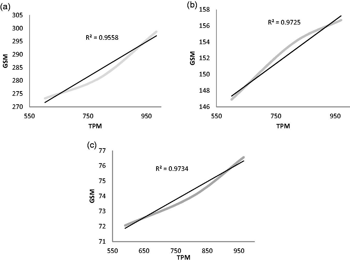
This dependence of amount of copper on the turns per meter (greater than 91%) can be well utilized to alter the percentage of conductive component in fabrics. Since the conventional method of changing the conductive component’s diameter to increase intrinsic electrical properties of the fabrics is associated with decreased EMSE capabilities, therefore, this proposed design will produce much better results, as it can produce yarns with greater percentages of conducting material without changing the conventional diameter increasing technique.
EMSE dependency on alignment and size of copper
Figure 7(a) to (c) presents the effect of proposed design on EMSE as compared to the conventional copper core fabric’s SE. The increase in SE values for fabric A, B and C ranges from 1% to 15% when the conventional copper core alignment was replaced with the proposed copper covering alignment at 25 TPI.
Comparison of proposed and conventional alignments for fabric A (a), fabric B (b) and fabric C (c), where Y-axis displays the EMSE values against the selected frequencies at X-axis.
Paired samples statistics.

The threshold frequency for fabric A2 is recorded at 3 GHz with maximum SE value of 34.5 dB, while for fabric B2 and C2, the threshold frequency is 4 GHz with SE values (maximum) of 33.7 and 34.6 dB, respectively. To further elaborate the lower threshold frequency for fabric A2, the optical porosity values of the fabrics are compared and are displayed in Figure 8. Transmission of light through the fabric is an established phenomenon to measure the porosity of fabrics and is known to have strong correlations with the air permeability values [30] (both being the measures to calculate porosity). The average porosity values are 2.9% + 0.48, 2.8% + 0.52 and 2.9% + 0.4 for fabrics FA3, FB3 and FC3, respectively, whereas, the porosity values for the proposed copper covering alignment fabrics are 7.2% + 0.26, 3.2% + 0.38 and 2.9% + 0.59 for FA2, FB2 and FC2, respectively. The alignment of copper as spiral covering on fibrous polyester core generally imparts two changes to the yarn structure, firstly, it reduces the bulkiness of the yarns, and secondly, it provides coverage for the hairiness of the fibrous core, which are both the measures for openness in any fabric structure [31]. For fabric FA2 (0.14 mm copper diameter), the copper wire provided maximum coverage of the fibrous polyester core as compared to the other groups of fabrics as shown in Figure 9, hence resulted in statistically significant increase in the optical porosity values (Wilcoxon Signed-rank test, z = −2.23, p < 0.043) as compared to the copper core fabric of the same genre. Since the amount of conducting material plays a vital role in determining the shielding effectiveness values towards low frequencies, while the openness and seem penetrations are more important factors towards higher frequencies [32], therefore fabric FA2, with highest porosity showed lower threshold frequency as compared to FB2 and FC2.
Optical porosity values in percentage for both alignments in Fabric A, B and C. Coverage provided by the copper spirals on core component of yarns.

Moreover, the use of finer metal filaments is more effective against EM shielding at higher frequencies [33], as the penetration depth is smaller for finer diameter wires (Skin effect), and the electrical field of a plain wave drops exponentially with increasing depth of the conductor [34], therefore fabric FC2 with the finest diameter amongst other fabrics, showed highest shielding effectiveness values (34.6 dB). This greater shielding effectiveness of finer wire in this study is in line with the findings reported by Cheng et al. [21], where they concluded lower shielding effectiveness values for coarse wires as compared to fine wires.
EMSE dependency on TPM of proposed conductive HCY
The dependency of EMSE and turns per meter of copper when it is aligned as a covering component in weft yarns is displayed in Figure 10. Since the turns per meter of copper covering in yarns changes the amount of copper in the fabrics, therefore, the fabric with greatest number of turns (greatest amount of copper) i.e. subscript 2, demonstrated maximum SE values in all fabric types and at all the frequencies.
TPM of copper covering and EMSE comparison for fabric A (a), fabric B (b) and fabric C (c), where Y-axis displays the EMSE values against the selected frequencies at X-axis.
The maximum increase in the value of SE ranges from 2 dB to 3 dB when the TPI of weft copper covering yarn in fabrics was increased from 15 to 25. However, no statistical significant difference in dB values (p value of 0.215, 0.185 and 0.363 for fabric A, B and C respectively) between the three TPI groups (15, 20 and 25 TPI) was observed using ANOVA analysis. Since the change in values of dB falls along a logarithmic scale (base 10), which means that a shielding of 10 times greater is obtained in 30 dB than in 20 dB [35], therefore the change of 3 dB implies a 3 fold increase in the SE, which is significantly high for a single layered fabric.
Electrical properties
The intrinsic electrical properties, such as conductivity and resistivity, can be deduced from the complex permittivity calculations, which can also lead to the prediction of EMSE at various frequencies [36]. The loss tangent results from the real and imaginary part of the complex permittivity were calculated using equation (4) and are displayed in Figure 11. For lossless materials, the value for loss tangent should be zero, whereas in case of a lossy material, this loss factor increases in order to accommodate the dielectric damping and conductivity losses of the medium.
Loss Tangent factor in proposed and conventional alignment for fabric A (a), fabric B (b) and fabric C (c), where Y-axis displays the loss tangent values against the selected frequencies at X-axis.
Fabric samples in subscript 2 for all the fabric types (A, B and C) showed higher loss tangent values when compared to the conventional alignment fabrics (subscript 3). This increase in the loss tangent values can be logically attributed to the greater metal content of fabrics in proposed alignment (as per equation (3)).
However, since the fabrics are flexible and compressible materials, their thickness and density might change with even a slight pressure, which may cause variations in their dielectric behaviour. Moreover, the effect of material thickness on the dielectric behaviour is very significant, the greater the thickness the less will be the dielectric constant and the loss tangent [37]. This effect of material thickness can also be observed in Figure 11, where the fabric sample C with the least thickness has more loss tangent values as compared to the other two samples at most of the frequencies.
Conclusions
The proposed alignment of copper covering on textile core in HCYs fabrics yielded significantly better results of EM shielding as compared to the conventional copper core fabrics. Moreover, the increased loss tangent value reflects its better conductivity as compared to the conventional alignment.
The maximum shielding effectiveness attained in the proposed alignment lie in the range of 33 to 34.6 dB, which is regarded as moderate/ excellent level of protection for professional/ general use with more than 99.9% shielding [38].
There was significant increase in the amount of copper in fabrics (15% to 62%) by aligning the copper filament in the proposed design; hence the problems associated with increasing the diameter of conductive component for increasing its amount to attain better EMSE (conventionally) can be addressed by this design. Furthermore, the effectiveness of finer wires against EM shielding (at higher frequencies) is greater than the coarse wires, which is due to reduced openness of the fabrics and reduced skin effect at higher frequencies.
The turns per meter of copper coverings are positively related to the total amount of metal in the fabrics, therefore the amount of metal can be controlled by altering the TPM of the of copper filament, which was only possible earlier by changing the size of copper.
The intrinsic electrical properties of fabrics such as conductivity can be accessed via the complex permittivity of the fabrics. The higher loss tangent value reflects better conductivity of the material and can be utilized to assess the SE of fabrics at various frequency ranges.
The proposed copper covering design is recommended for E-textiles, based on its effective control for amount of copper, where higher EM shielding is required. Furthermore, the copper covering yarns, with finer covering filaments, can be woven at higher cover factors to further assist in providing maximum shielding at minimum fabric openness.
Footnotes
Acknowledgements
The authors would like to acknowledge the continuous support and technical guidelines provided by Dr. Mohamad Huzaimy Bin Jusoh and Dr. Ahmad Asari Bin Sulaiman from the Applied Electromagnetic Research Group, Faculty of Electrical Engineering, Universiti Teknologi MARA, Shah Alam, Selangor, Malaysia. The authors would also like to acknowledge the assistance provided by the Research Management Centre (RMC) of Universiti Teknologi MARA.
Declaration of Conflicting Interests
The author(s) declared no potential conflicts of interest with respect to the research, authorship, and/or publication of this article.
Funding
The author(s) received no financial support for the research, authorship, and/or publication of this article.