
Abstract
Objective
Knee orthoses assist patients with joint instability, yet many passive designs provide limited energy dissipation and flexion-load regulation during high-demand activities. This study designed and validated a compact three-spring shock-absorption mechanism to provide quasi-passive flexion resistance, improve energy absorption, and redistribute loads in knee orthoses.
Methods
A mechanical design and validation study was conducted combining analytical modeling, finite-element simulation, and pilot functional testing. The mechanism integrates two compression springs and one tension spring housed in an aluminum frame. Finite-element simulations (ANSYS Explicit Dynamics®) evaluated deformation, absorbed energy, and von Mises stress under dynamic loading over a 0–70° motion range, and were calibrated using experimental compression/tension tests of single and paired springs. Three functional prototypes were fabricated and evaluated by three adult volunteers using one-leg rise and deep-squat tasks, with perceived assistance recorded on a 100-mm Visual Analogue Scale (VAS) under institutional ethics approval.
Results
Simulated and experimental endpoint force and total deformation (L0 – Lf) showed close agreement, with relative deviations below 3%. For the evaluated configuration, the orthosis generated an estimated total passive flexion resistance of 70.54 Nm for two modules, corresponding to a case-specific 48.22% reduction in required flexion torque when referenced to a representative post-ACLR peak torque (146.30 Nm). Peak stresses remained below the yield strength of 6061-T6 aluminum, while the beam–base interface was identified as the durability-critical region. Functional testing yielded mean VAS scores of 36.67 ± 2.89 (one-leg rise) and 41.67 ± 5.77 (deep squat), indicating moderate perceived assistance.
Conclusions
The proposed multi-spring mechanism provides measurable quasi-passive resistance and withstands conservative high-flexion loading, supporting its feasibility as a compact assistive concept. These proof-of-concept results motivate further work on fatigue/wear assessment, multi-objective optimization, and larger clinical studies with objective functional outcomes.
Keywords
Introduction
Knee osteoarthritis (OA) and post-injury ligament instability represent major causes of chronic pain and disability in adults, particularly in aging populations.1–2 Non-surgical management commonly relies on knee orthoses to stabilize the joint and enable controlled motion during rehabilitation. 3 However, the clinical efficacy of current passive devices remains limited in some reports; pain relief does not exceed 5–6% in medial OA patients using lateral wedge insoles.4–5 This highlights the need for improved mechanical designs capable of redistributing loads and providing adaptive resistance.
Recent orthotic designs aim to improve stability, mobility, and comfort in patients with impaired knee function. Stance Control Orthoses (SCO) lock the knee during stance and allow swing-phase motion, enhancing gait safety, 6 whereas spring-based clearly support systems such as the Spring Brake Orthosis (SBO) incorporate compliant elements and, in some implementations, Functional Electrical Stimulation (FES). 7 Modular braces enable patient-specific alignment in the anteroposterior and mediolateral planes to reduce distal migration, 8 and commercial devices (e.g., SofTec OA®, Genu Arthro®, and Ortho Pro®) use pneumatic/elastic elements to apply adjustable valgus forces and provide flexion-extension damping.9–10 In contrast to gait-focused spring-based designs, the present multi-spring mechanism is conceived as a compact, quasi-passive shock-absorption module for sagittal-plane high-flexion activities, emphasizing energy dissipation and experimentally calibrated passive resistance with minimal mechanical complexity and without actuators or control electronics.
In parallel, bio-inspired designs, including rolling-gear, five-bar linkage, and adaptive cross-configured systems, seek to replicate the knee's natural motion while minimizing weight and misalignment.11–13 Optimized gear-link, polycentric, and modular mechanisms have demonstrated improved kinematic compatibility, energy absorption, and reduced device migration compared to single-axis systems, particularly during high-flexion activities such as sitting, rising, and squatting.14–16 In this context, active knee orthoses and exoskeletons have shown that deep flexion tasks, such as sit-to-stand, may require extension torques exceeding 120 Nm 25 ; however, system weight and mechanical complexity emphasize the need for lightweight passive or quasi-passive shock-absorption solutions. Collectively, these findings indicate a trend toward compact, mechanically compliant orthotic designs for demanding daily activities.
From a modeling perspective, the biomechanical analysis of knee orthoses has increasingly relied on multibody modeling (MBM) to describe joint kinematics, constraint interactions, and force transmission in systems composed of rigid bodies interconnected by joints and elastic elements. MBM formulations have been widely used to estimate joint moments, spring forces, and energy exchange during knee flexion–extension under physiological conditions.26–27 In the present investigation, the shock-absorption mechanism is modeled as a multibody system comprising rigid beams, axial bars, and springs, which collectively govern the global mechanical response prior to structural evaluation.
Complementarily, the finite element method (FEM) has been extensively applied in the biomechanical analysis of the knee under various loading conditions and is commonly integrated with multibody models to evaluate structural integrity, local stresses, and contact interactions.17,27–28 FEM has been employed in the analysis of knee implants compatible with Anterior Cruciate Ligament Reconstruction (ACLR), incorporating bone grafts and evaluating mechanical behavior. 18 It also plays a crucial role in design optimization, including the development of hybrid adapters for transfemoral prostheses and the dimensional optimization of knee orthoses to reduce weight while improving load redistribution.19–20 Additional applications include adaptive knee orthoses with variable rotation centers and optimized foot orthoses for midfoot arthritis.21–22 Nevertheless, few studies integrate FEM-based structural analysis with experimental calibration and preliminary human validation within a single investigation.
Regarding knee joint loading, quadriceps moments can be up to three times greater during deep flexion than during normal gait, potentially increasing joint stress and compromising ligament stability. 23 Additionally, measurements obtained using an isokinetic dynamometer indicate that limbs following ACLR can generate a peak torque of 2.09 Nm/kg, whereas the contralateral limb can produce 2.33 Nm/kg, highlighting asymmetries in muscle strength post-reconstruction. 24
In this context, the present study develops and validates a novel three-spring shock-absorption system designed to enhance passive resistance and reduce flexion-induced stress on the knee joint. The design is guided by explicit mechanical performance criteria, including the regulation of flexion-related loads during high-demand tasks, the maintenance of structural stresses within allowable material limits, and stable force transmission across the full operating range of knee motion. Numerical simulations and physical testing are employed to verify that these criteria are met, followed by a preliminary exploratory evaluation involving human participants. The overall goal is to establish a transferable mechanical framework supporting future optimization and clinical validation of energy-absorbing knee orthoses.
Methods
The methodology combined analytical modeling, finite-element simulation, and experimental validation to characterize the proposed shock absorption system. The workflow consisted of: (1) conceptual modeling of beam–spring interactions; (2) FEM simulations to evaluate dynamic performance; (3) laboratory testing of spring stiffness; and (4) prototype fabrication with preliminary functional assessment. The following subsections describe each stage.
Conceptual modeling of the beam–spring system
Figure 1(a) illustrates one of the two shock absorption systems integrated into each knee orthosis, specifically shown on the right leg of a patient. The shock absorption system consists of two helical compression springs and a third extension spring, which can alternatively be replaced with an elastic tensioner. As shown in Figure 1(b), these springs function through the action of two guide beams, which can freely rotate to the left up to a maximum angle of 70°, representing deep flexion angles (130°–140° anatomical range). A central slot allows axial displacement to prevent premature solid height contact, while a side slot accommodates the tension element.

Shock absorption mechanism integrated into the right leg orthosis: (a) mounted within the fabric sleeve; (b) internal structure showing dual compression and single extension springs.
The kinematic model was simplified as two rigid beams and two axial bars coupled to three springs (two in parallel, one in tension). Figure 2 illustrates the shock absorption system used to determine the forces at points A and H, displacements Δ2 and Δ3, angle variations θ1 and θ2, the tension spring displacement (ΔTens), and the resulting moments. Elements A–C, K–L, H–J, and M–N are modeled as rigid beams transmitting forces and bending moments, whereas elements D–E and F–G are treated as axial bars connecting the compression springs to the articulated beams. Beam A–C is 28 mm long with a rotation point at B (12.5 mm). Bar D-E is 25.40 mm long and moves downward only. Beam H–J is 28 mm long with a rotation point at I (12.5 mm). Bar F–G is 25.40 mm long and moves upward only. Two parallel springs are positioned between bars D–E and F–G, each with a free length of 25.40 mm, a solid height of 15.00 mm, a maximum compression of 10.40 mm, which is shown as half of 5.2 mm in Figure 4, and a stiffness of 15370 N/m. To incorporate the third elastic element, beam A–C was connected to beam H-J at points C and J. This tension spring has a resting length of 47.90 mm and a stiffness of 2421 N/m. All stiffness values were experimentally determined. Additionally, rigid beam elements A–C and K–L guide femoral motion, while rigid beam elements H–J and M–N represent tibial movement. The lever arms from point A to K and from H to M each measure 123 mm.
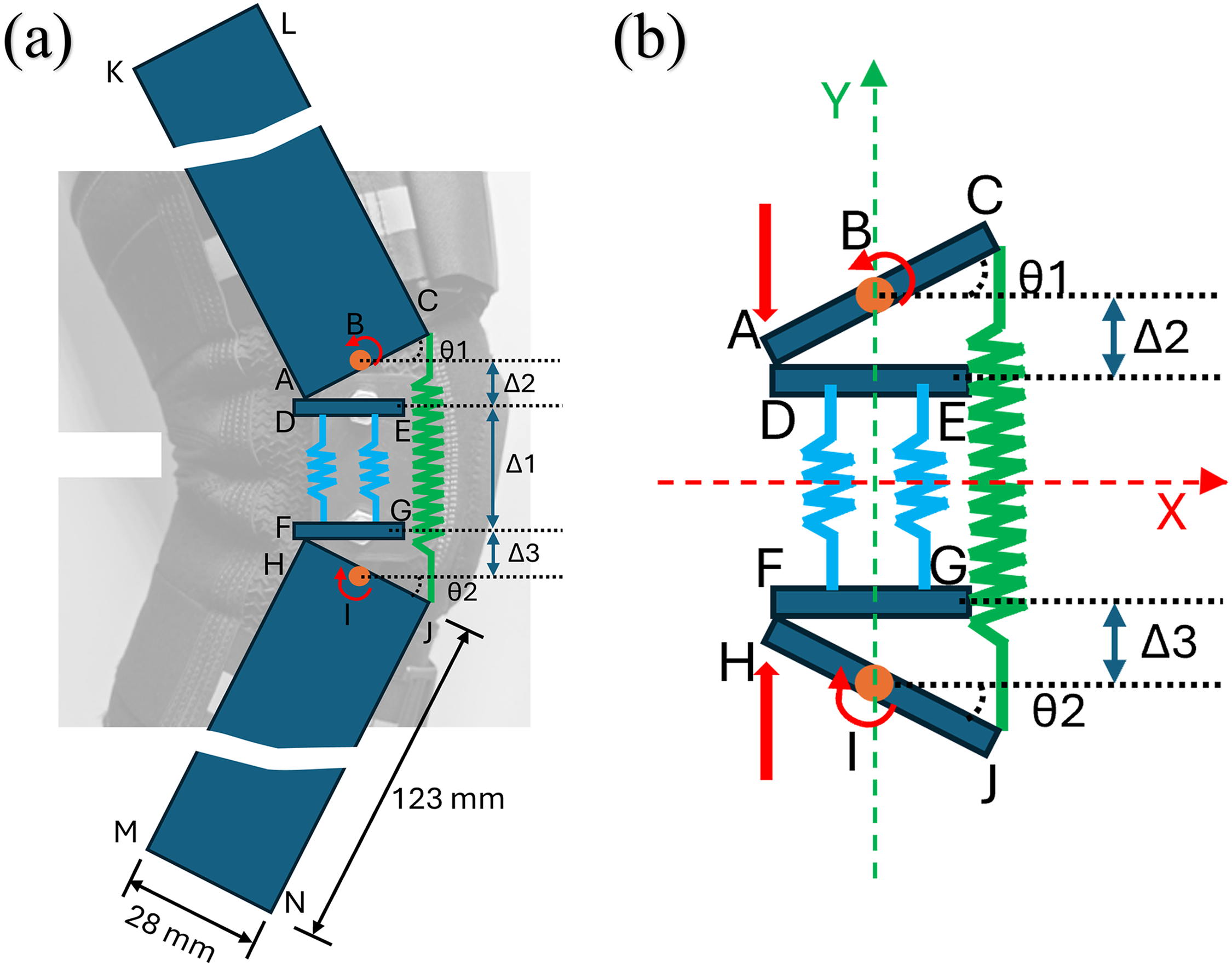
Simplified analytical model of the beam–spring system: (a) sagittal knee configuration; (b) schematic representation showing rotation and spring forces.
Finite-element simulation and dynamic performance evaluation
Finite-element simulations were performed in ANSYS Explicit Dynamics® to analyze the structural response of the multi-spring mechanism under dynamic compression and extension. This solver was selected for its capability to capture nonlinear contact interactions, spring detachment, and time-dependent deformation. Beam elements govern the kinematic and moment-transmitting behavior of the mechanism in the multibody formulation, whereas bar elements primarily transfer axial loads. Hereafter, the term “base” refers to the axial bar elements (D–E and F–G) that support the compression springs and undergo translational displacement, whereas the articulated members (A–C, K–L, H–J, and M–N) are referred to as beams. The structural response of both components, including von Mises stress and strain, is evaluated through finite element analysis, while the dynamic response accounts for translational and rotational kinematics and associated energy components, including kinetic energy, elastic potential energy, and dissipated energy components.
Two simulation series were conducted. (1) Validation simulations replicated laboratory compression and tension tests. (2) System-level simulations incorporated the rotating guide beams, enabling spring displacement within a 0–70° flexion range.
In the validation simulations, tests 1–4, 6, and 8–9 were used to calibrate spring constants against force-deformation responses (Tables 1 and 2). Tests 5 and 7 isolated the spring subsystem by omitting the articulated beams and adding four fixed intermediate plates (Table 2). Figure 3(a) illustrates the model used in test 5, where the compression of four springs is simulated. Figure 3(b) shows the boundary conditions and applied loads; in this case, the intermediate plates were fixed, and axial forces and displacements were applied along the Y-axis.
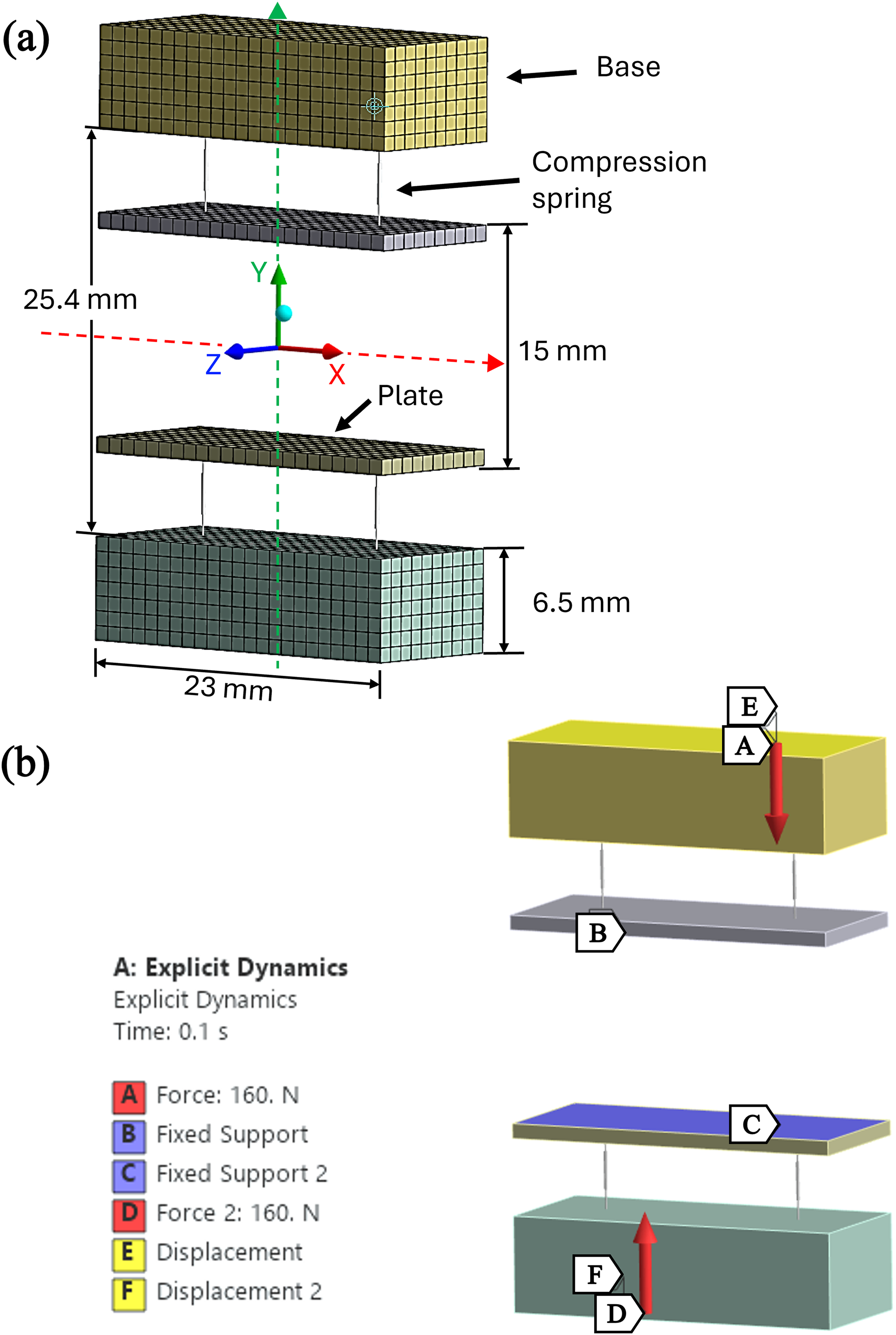
Simulated four-spring compression setup (test 5): (a) 3D mesh; (b) boundary conditions and applied loads.
Representative experimental results of compression and tension tests.

Note: Stiffness computed from experimental data.
Numerical simulation results of compression and tension tests.
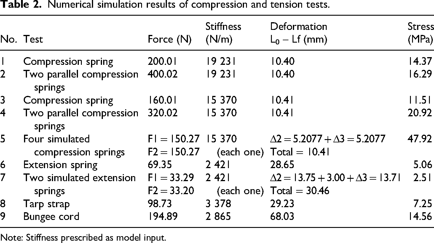
Note: Stiffness prescribed as model input.
The second simulation series models the complete shock-absorption system. Figure 4(a) shows a sagittal-plane view of the beams, axial bars, springs, and joints, and Figure 4(b) presents the 3D mesh (51,704 Hex8 elements; 67,776 nodes) with element sizes of 0.7 mm for beams and 1.0 mm for bases and plates. Frictionless and bonded contacts were assigned to adjacent and permanently connected interfaces, respectively. Figure 4(c) shows the boundary conditions and loading (fixed supports and imposed axial displacements); the applied load corresponds to a 114.02 N resultant from 70 N (X) and 90 N (Y). Revolute joints allow sagittal-plane rotation of the beams, while axial bars serve as translational bases for the compression springs.
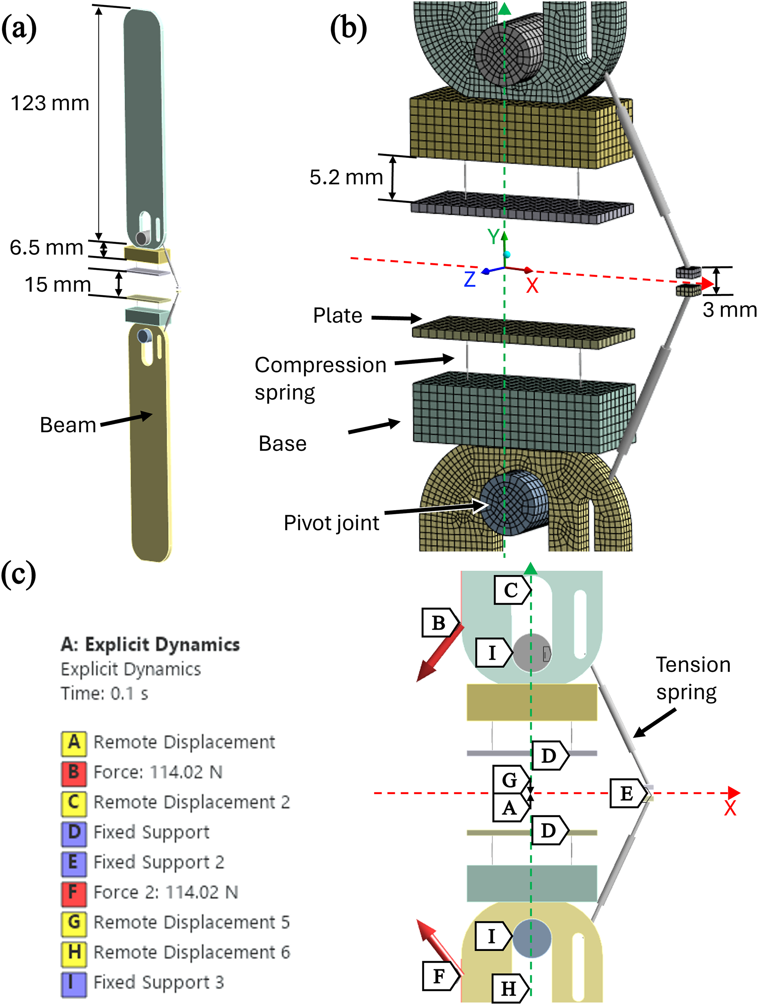
Shock-absorption system: (a) sagittal-plane view; (b) 3D mesh; (c) boundary conditions and applied loads.
The two central plates, 15 mm apart, represented the solid height of the compression springs, while two lateral plates, 3 mm apart, modeled the extension spring center. Each real spring was divided into four numerical segments, maintaining equivalent stiffness and overall force equilibrium. This configuration ensured realistic deformation behavior and alignment between simulated and experimental results.
Experimental validation and prototype testing
For the experimental tests, a Universal Testing Machine TecQuipment mod. SM1000 was used. The tests listed in Table 1 involved evaluating individual and parallel compression springs (Figure 5(a)), extension springs, tarp straps (Figure 5(b)), and bungee cords (Figure 5(c)) as potential substitutes for the extension spring in an alternative configuration. Each spring or tension element type was subjected to ten consecutive tests to ensure repeatability and statistical reliability of the results.

Experimental testing setup: (a) compression of dual springs; (b) tension testing of elastic strap; (c) bungee-cord evaluation.
Three functional prototypes were fabricated for experimental evaluation using aluminum guide beams and additively manufactured polyamide (PA) joint housings/axial elements (impact strength 70–100 J/m; tensile strength 45–65 MPa). The shock-absorption module is enclosed in a PA casing that serves as the joint housing and spring guide, accommodating two parallel compression springs and a lateral extension spring (Figure 1). The module is coupled to the orthosis via two aluminum guide beams fastened with through-bolts, washers, and locknuts, forming a revolute (pin) joint for sagittal-plane rotation. Potential wear is expected mainly at the beam–housing interface and spring seats; polymer contact surfaces reduce fretting, while liners/coatings or improved surface finishing will be evaluated in future cyclic durability testing.
The prototypes were evaluated by volunteers with prior knee conditions (two with bilateral patellofemoral chondromalacia and one following hemiepiphysiodesis surgery). The study aimed to evaluate the passive resistance and user comfort provided by the orthosis. Functional assessment was conducted through the one-leg rise and deep-squat tasks, both representing high-demand flexion scenarios. A 100-mm Visual Analogue Scale (VAS) was employed, where 0 indicated no perceptible assistance and 100 indicated maximum spring contribution to flexion-extension movement. Because no universal benchmark exists for perceived assistance VAS in knee orthoses, the scores were interpreted using the standard VAS framework commonly used in ACLR-related functional testing, in which the scale spans from the absence of the rated sensation to its maximum intensity. 24 Accordingly, the observed ratings (∼37–42 mm) represent ∼40% of the maximum perceived assistance, supporting their interpretation as moderate rather than minimal or near-maximal.
Results and discussion
This section presents the outcomes of experimental testing, numerical simulations, and analytical modeling of the multi-spring shock absorption system. The discussion emphasizes the mechanical correlation between predicted and measured results and interprets their biomechanical relevance for knee orthoses.
Experimental and numerical validation of spring behavior
Experimental compression and tension tests were conducted to obtain representative force–deformation responses of the spring elements. These experimental results are summarized in Table 1, while the corresponding numerical predictions are reported in Table 2. Both single- and dual-spring configurations exhibited linear load–deflection behavior up to solid height. Because the test bench does not record continuous displacement, agreement was evaluated using endpoint values (final force and L0 – Lf deformation). Across all tested elements, the maximum relative deviation was <3% for both force and deformation (worst case: 2.56% and 2.54%, respectively). Stiffness values were prescribed as model inputs; therefore, validation is reported in terms of force and deformation.
For simulation test 4 with two parallel springs, the lower end was fixed, and a 320 N load was applied to the upper base. The springs deformed 10.41 mm, with each supporting 160.01 N, totaling 320.02 N of elastic force.
Tests 5 and 7 were performed exclusively through numerical simulation. In test 5, the two physical parallel compression springs were represented as four simulated springs to reproduce the same stiffness distribution using intermediate plates. Figure 6 shows the Y-axis directional deformation, indicating an axial compression of 5.2077 mm at each end, for a total spring deformation of 10.4154 mm, which is slightly higher than the 10.40 mm measured experimentally.

Test 5 four-spring model: (a) loading and displacement configuration; (b) Y-axis directional deformation during compression, including the undeformed reference position.
This simulation is equivalent to test 4 (both experimental and simulated), where two parallel springs support 320 N. However, since there are intermediate plates that prevent the transmission of force, the springs act independently, so 160 N is applied at each end, with each spring supporting 80 N.
Figure 7 shows the equivalent (von Mises) stress for the bases in test 5, with a maximum value of 47.915 MPa at the upper base, where a 160 N force is applied and transmitted to the compressed parallel springs. The generalized stress ranges between 0.00 and 34.226 MPa for both bases, remaining below the yield strength and ultimate tensile strength of 6061-T6 aluminum.
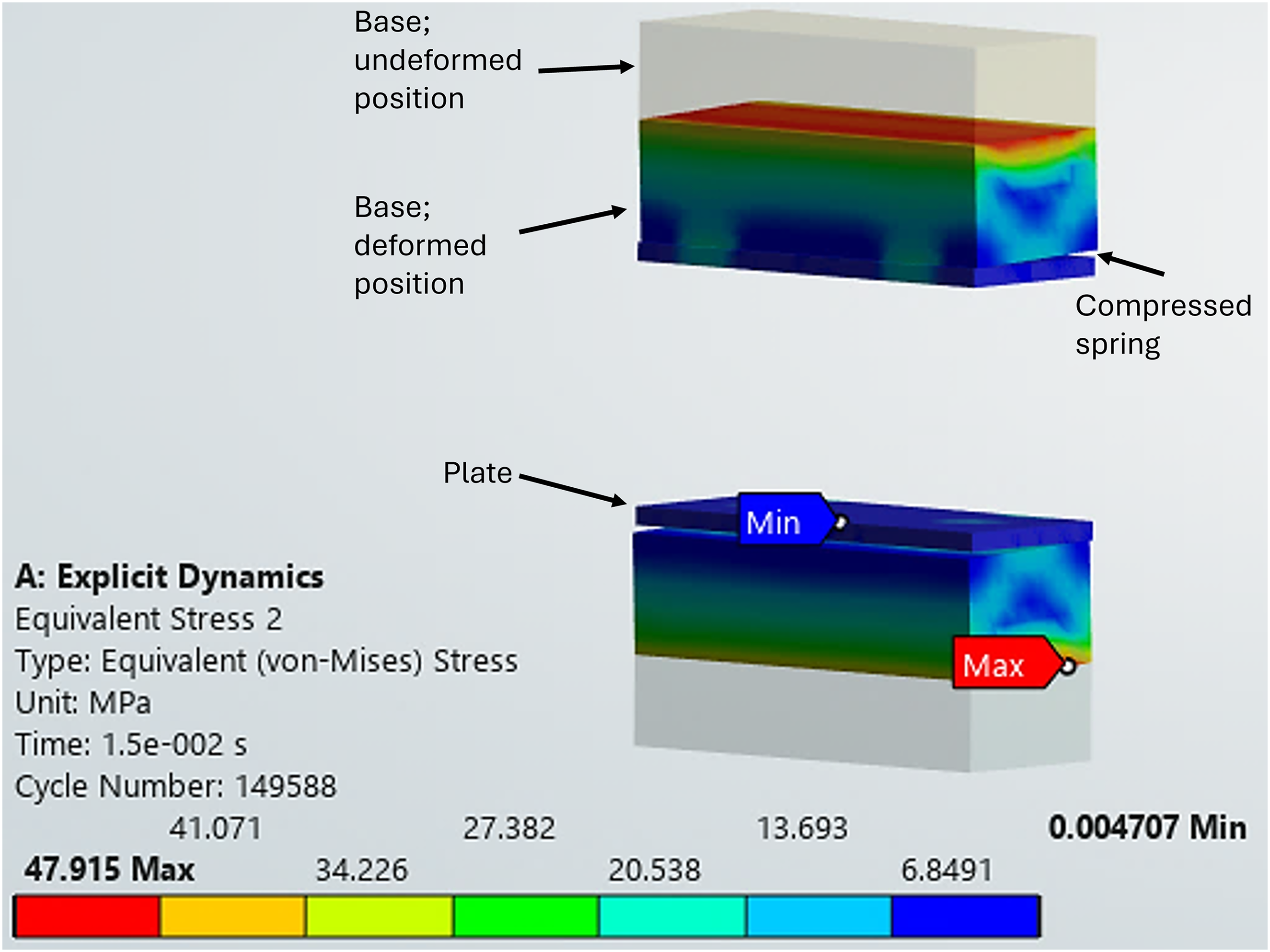
Stress in the simulation of test 5 during the compression of four springs, with the undeformed reference position overlaid.
Analytical and numerical correlation
Table 3 presents the analytical results for the beams and three-spring system, showing inclination angles from 0° to 70° at rotation points B and I. Compression-spring displacement (Δ2, Δ3) and tension-spring extension (ΔTens) were obtained using CAD model analysis for each angle, as distances A–B and H–I vary due to a 10-mm corner radius at points A and H.
Analytical results of the beam-spring system.

At 70°, the tension spring remains within its maximum extension of 76.81 mm; however, the parallel springs are compressed by 11.22 mm, exceeding the experimental limit of 10.40 mm. This situation is corrected both in the numerical simulation and in the real system, since the guide beams have a central slot, which allows both rotation and displacement to compensate for the difference of 0.82 mm.
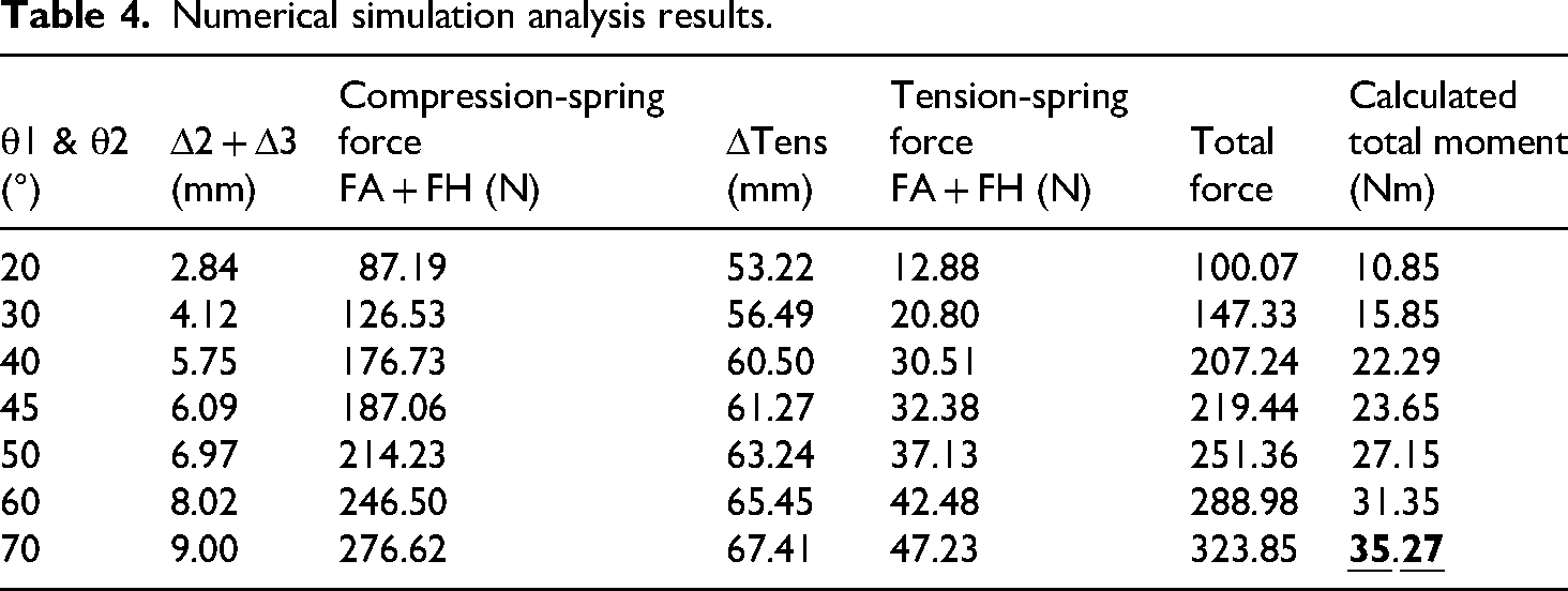
After validating the simulation parameters for realistic behavior, simulations were conducted to characterize the motion of the shock absorption system within the mechanical orthosis. The initial conditions included the spring stiffness and applied force, while the displacement of the bases on the springs was obtained. The results of the numerical simulation, including the total moment calculated analytically from numerical data, are presented in Table 4.
Numerical simulation analysis results.
When the beams rotate 70°, the bases move toward the center, compressing the four simulated springs. Figure 8(a) illustrates this mechanism-level behavior, showing the inward motion of the bases and the resulting spring compression. Figure 8(b) presents the initial and final positions from the directional deformation results, where the upper base descends 5.2022 mm and the lower base ascends 5.0088 mm, totaling 10.211 mm. This nearly symmetric compression aligns with theoretical predictions and supports the consistency of the structural and numerical model.
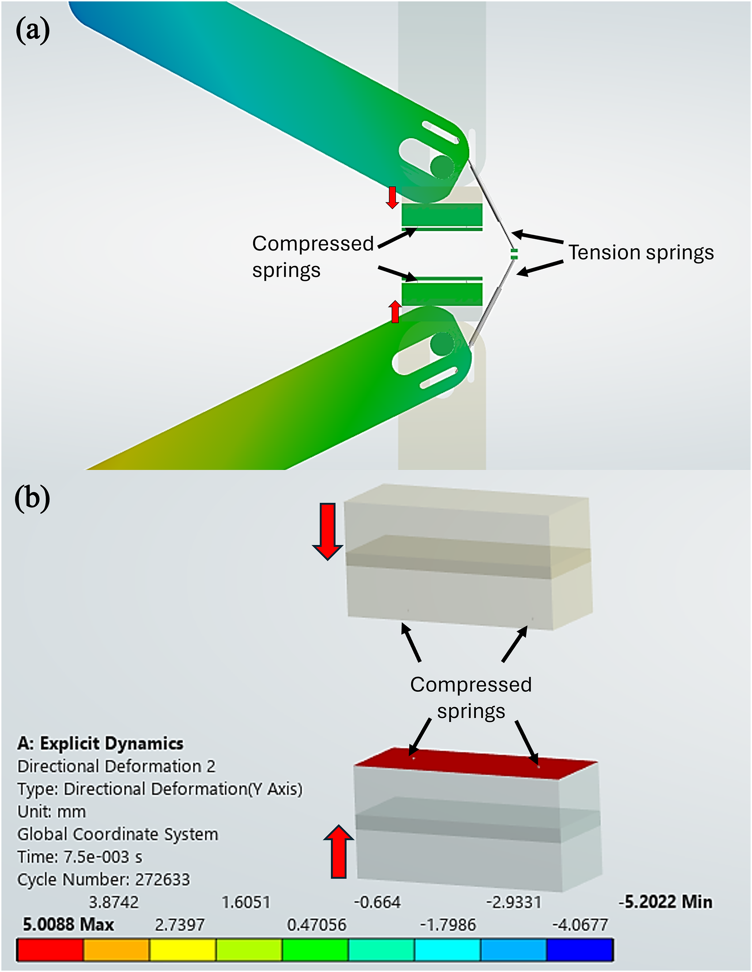
Directional deformation at 70° beam rotation: (a) system configuration; (b) Y-axis displacement of the upper and lower bases.
In Figure 9(a), the equivalent (von Mises) stress results are shown for a 70° beam rotation (sagittal-plane view). The analysis confirms a high stress concentration at the contact interface between the beam and the base, reaching 207.76 MPa, which remains below the material's yield strength of ∼275 MPa. Although this peak occurs under the critical condition of deep squatting, and does not indicate immediate failure, it represents a localized contact/discontinuity concentration that may be fatigue-critical under repetitive loading. Since 6061-T6 does not exhibit a true endurance limit, long-term durability should be assessed using an S-N-based fatigue evaluation of the local stress amplitude at the beam-base interface, complemented by cyclic testing. This 70° case represents a conservative deep-squat condition; therefore, future redesigns (e.g., larger fillets, local thickening, and/or surface treatments) can further reduce concentration and improve long-term durability.

Von Mises stress at 70° guide-beam rotation: (a) beam–base contact with the undeformed model overlaid; (b) base–plate contact at the two compression-spring locations.
Similarly, Figure 9(b) illustrates the compression behavior but only of the base against its plate. The stress in the plate is reported to verify that this load-transfer component remains non-critical and to indicate how the normal load is distributed through the two parallel compression springs. The base experiences mostly uniform compression, with stress values ranging from 0.00 to 11.362 MPa. As expected, the maximum stress (26.511 MPa) occurs at the spring–plate contact points. All values remain below the yield limit of 6061-T6 aluminum, indicating elastic behavior under these conditions.
Although frictionless contact was assumed to isolate normal load transfer, the beam-base and base-plate interfaces may experience friction and wear during repeated flexion-extension cycles. Wear is expected to increase with contact pressure and sliding distance; thus, low-friction liners/coatings or improved surface finish may mitigate fretting and abrasion. Frictional-contact modeling and tribological testing will be addressed in future work.
Estimated torque assistance
The moment generated when sitting can be approximated using the moment equation. For example, a 70-kg (686.47 N) patient with a 0.4-m distance from the center of mass to the knees, at a 90° femur-tibia angle, would generate 274.59 Nm across both knees and 137.29 Nm per knee. These results are consistent with isokinetic dynamometer data, where a 70-kg patient can generate an average peak torque of 146.30 Nm with the ACLR limb, while the contralateral limb can produce 163.10 Nm. 24 Therefore, considering a post-ACLR operated limb (146.30 Nm), the passive resistance of the orthosis reduces the required flexion torque to 75.76 Nm, representing a 48.22% reduction.
This reduction may be increased by selecting stiffer springs, subject to space and solid-height constraints. The reported value is case-specific; in general, the mechanism provides angle- and task-dependent passive flexion resistance, and the percentage reduction scales with the required knee-joint torque (higher-demand conditions yield smaller reductions, and vice versa).
Functional prototype evaluation
From the sagittal knee position, when a person sits, the femur tilts 90° relative to the tibia, while in a deep squat, it reaches 130°–140°. This correlates with the inclination angles of the articulated beams in the shock absorption system, as shown in Figure 10. In these positions, the shock absorption system is inclined. When seated, the guided beams are positioned at 45°, or a combination of 40° and 50°, summing to 90° (Figure 10(a)). Similarly, in a deep squat, the beams reach a maximum angle of 70°, or a combination between 60° and 70° to achieve the 140° deep squat position (Figure 10(b)).

Sagittal positions of the orthosis: (a) sitting at 90°; (b) deep squat at 140°.
According to the simulation, at a maximum inclination of 70°, the parallel springs compress by 9.00 mm, the tension spring extends to 67.41 mm, and the total generated force is 323.85 N (33.02 kgf). This falls within the expected range and aligns with the experimental results from tests 4 and 6, where 390 N (39.76 kgf) were required to compress the springs 10.40 mm and extend the tension spring to 76.81 mm. At this inclination, the generated moment is 35.27 Nm, closely matching the analytical calculation at 57° (35.34 Nm). This variation is due to the greater influence of spring length and compression force on the angle in the moment calculation. Since the knee orthosis incorporates two shock absorption systems, the total passive resistance for flexion is 70.54 Nm.
Clinically, the stress distribution suggests that the mechanism withstands the evaluated high-flexion loading without yielding, while identifying the beam–base interface as the durability-critical region under repetitive use. The predicted passive resistance provides partial assistance that may reduce flexion torque demand during tasks such as sitting and deep squat, potentially lowering muscular effort in users with reduced strength (e.g., post-ACLR). These preliminary implications should be confirmed in larger clinical studies with objective outcomes.
Given the small sample size (n = 3), the functional evaluation focused on perceived assistance. Participants performed one-leg rise and deep-squat tasks while wearing the orthosis, and a single VAS score was recorded immediately after each task. Individual scores and the corresponding mean (SD) are reported in Table 5.
Perceived assistance during functional tasks (VAS, n = 3).

Based on the estimated passive resistance reported above, the orthosis provides partial assistance during high-flexion tasks. The VAS ratings serve as a subjective indicator of perceived assistance rather than a calibrated mapping to the predicted torque reduction. The one-leg rise test yielded a mean score of 36.67 ± 2.89, while the deep squat test yielded a mean score of 41.67 ± 5.77, indicating moderate perceived assistance under demanding flexion conditions. Values are presented as mean ± standard deviation (SD).
To contextualize these preliminary outcomes, a comparison can be made with active knee orthoses that provide controlled assistance during demanding tasks. An active knee orthosis with a motorized dual-clutch variable transmission reported that sit-to-stand/stand-to-sit may require peak knee torques of ∼120–128 Nm and therefore targeted partial assistance of ∼30% (≈38 Nm). 25 In contrast, the present device provides quasi-passive assistance through spring-based flexion resistance, avoiding actuators and control hardware. For the evaluated configuration, the orthosis generates an estimated total passive flexion resistance of 70.54 Nm (two modules) and corresponds to a predicted 48.22% reduction in required flexion torque when referenced to a representative post-ACLR peak torque (146.30 Nm).
Compared with unloader braces, which primarily offload knee compartments in the frontal plane and may reduce pain and moments during functional tasks, 15 the present mechanism targets sagittal-plane flexion resistance using a compact spring-based module. Likewise, stance-control orthoses (SCOs) mainly lock/unlock the knee to improve gait stability rather than to reduce deep-flexion torque demands. 6 Therefore, the proposed device addresses a complementary objective: providing mechanically simple, quasi-passive support during high-flexion activities (e.g., sitting and deep squatting). A direct weight/cost benchmark versus specific commercial products is outside the scope of this proof-of-concept and will be reported in future work.
These preliminary findings support the feasibility of the orthosis for providing passive resistance during high-flexion tasks. While perceived support varied, all participants reported improved knee mobility and stability. However, a larger clinical study is required to evaluate clinical adaptability, user perception, and objective functional outcomes.
Conclusions
This study demonstrated the feasibility and mechanical efficiency of a compact three-spring shock absorption system designed for knee orthoses. The proposed configuration effectively redistributes loading, attenuates flexion-induced stresses, and provides measurable passive resistance during motion.
For a representative post-ACLR reference torque (146.30 Nm), the estimated total passive flexion resistance of the orthosis (70.54 Nm, considering two shock-absorption modules) reduces the required flexion torque to 75.76 Nm, corresponding to a 48.22% reduction. This level of assistance may be increased by selecting higher-stiffness springs, although space constraints and solid-height limitations must be considered.
The proposed model was validated through numerical simulations and experimental tensile and compression tests using endpoint force and total deformation (L0 – Lf), showing a maximum relative deviation below 3% across all tested elements (worst case: 2.56% in force and 2.54% in deformation). The simulations also identified critical stress concentration regions and quantified spring deformation under load, confirming the structural capacity of the mechanism under high flexion loading conditions.
A preliminary proof-of-concept functional evaluation was performed with three participants using a 100-mm Visual Analogue Scale (VAS) to quantify perceived assistance. The mean score was 36.67 ± 2.89 during the one-leg rise test and 41.67 ± 5.77 during deep squats, indicating moderate perceived support during high-flexion activities. These outcomes should be interpreted as exploratory due to the limited sample size.
Future research should focus on larger-sample clinical trials, fatigue and wear assessment of the spring–beam assembly and contact interfaces, and multi-objective optimization of spring selection and geometry. These developments will further improve durability, user adaptability, and clinical relevance in rehabilitation applications.
Footnotes
Acknowledgments
The authors have no acknowledgments to declare.
ORCID iDs
Ethical considerations
This study was approved by the IPN ESIME and conducted in accordance with the Declaration of Helsinki. The study was classified as low risk because it involved mechanical evaluation of non-invasive orthotic devices and did not require medical intervention.
Consent to participate
Written informed consent was obtained from all participants prior to inclusion in the study. Each volunteer received a full explanation of the study objectives, device operation, and the right to withdraw at any stage without consequence. No personal identifiers or clinical histories were recorded, ensuring participant anonymity.
Consent for publication
All participants provided written informed consent for publication of anonymized data, images, and results related to their participation. No identifiable personal or medical information is presented in this manuscript.
Author contributions
Víctor Hernández-Hernández: conceptualization; investigation (finite-element simulations and prototype-related testing); data curation; validation (experimental–numerical comparison); writing—original draft; writing—review and editing. Orlando Susarrey-Huerta: methodology; mechanical design; analytical and multibody (MBM) modeling; supervision; project administration; writing—review and editing. Usiel S. Silva-Rivera: supervision (finite-element modeling workflow); formal analysis and interpretation; visualization; writing—review and editing. Wilbert D. Wong-Angel: methodology (biomechanical/functional input); investigation (mechanical testing); resources; validation; writing—review and editing. Osvaldo Quintana-Hernández: investigation (prototype fabrication/assembly and testing support); resources; visualization; writing—review and editing.
Funding
The authors gratefully acknowledge the financial support provided by the Secretaría de Ciencia, Humanidades, Tecnología e Innovación de México (SECIHTI), formerly the Consejo Nacional de Ciencia y Tecnología (CONACYT), which awarded a doctoral fellowship to Víctor Hernández-Hernández in support of this research.
Consejo Nacional de Humanidades, Ciencias y Tecnologías.
Declaration of conflicting interests
The authors declared no potential conflicts of interest with respect to the research, authorship, and/or publication of this article.
Data availability
The datasets and simulation files supporting the findings of this study are available from the corresponding author, Usiel S. Silva-Rivera, upon reasonable request. All numerical models were implemented in ANSYS Workbench® and Python and can be shared for academic use under institutional agreement.