
Abstract
The finger lock in the retractable actuator of the landing gear will wear during repeated unlocking and locking. Therefore, the effects of six parameters including the material of the finger lock, the length of the finger lock, the diameter of the finger lock, the number of petals, and the angle of the fingertip on the unlocking force after 500 unlocking cycles are researched. Archard wear theory was performed to obtain the unlocking force after wear and the influence of six key parameters on the unlocking force in this paper. Then, wear experiment was designed and the effectiveness of model and the influence of six parameters were verified. The results show that the chamfers of the finger lock was most worn, causing the value of the axial unlocking force during the transition phase to increase, but it has little effect on the maximum unlocking axial force. The material of the lock has little effect on the axial force; the length, diameter and the number of petals are inversely proportional to the axial force, and the angle of the fingertip is proportional to the axial force. Using Archard method can effectively calculate the finger pattern wear of locks.
Introduction
The landing gear is an important mechanism when the aircraft is taking off and landing. When the landing gear is extended, the lock mechanism 1 will complete the lock to fix the landing gear so that the aircraft can take off and land safely. Therefore, the landing gear lock mechanism normal working is directly related to the aircraft’s take-off and landing safety 2 and it is an important part of the landing gear design.
During the use of the aircraft landing gear, the lock mechanism will gradually wear during the unlocking process, which seriously affects the service life of the finger lock. 3 If the wear is within the specified range, the lock mechanism can maintain normal working conditions. If it exceeds the upper limit of wear, the friction force of the friction pair formed by the lock mechanism will rise sharply, 4 resulting in a retractable failure of the landing gear. 5
The wear problem has been studied at home and abroad for a long time. 6 For example, in reference,7,8 wear in complex working conditions will affect the dynamic performance of the mechanism. Wear is a phenomenon in contact. Hertz 9 contact and Coulomb 10 friction theorem are commonly used to calculate friction in contact theory. They are the basis of wear calculation. Archard 11 in the United Kingdom and Bayer in the United States have established effective wear calculation models. Among them, the most widely used is the Archard theory, which is used in12,13 for wear calculation. The wear problem in the aircraft mechanism can also use the wear calculation model. For example, in the reference, 14 the wear of aircraft tires was studied using the Archard theory, and in, 15 a certain joint of the aircraft was studied using the Archard wear theory. However, the relevant reference on the wear of the lock mechanism is still scarce. In reference 16 using the energy density method to predict wear, the wear result of single finger lock is obtained.
In actual use, it can be found that the unlocking force of the finger lock will change in one normal working cycle (500 unlocking cycles), which will affect the stability of the landing gear retraction and even cause seizure. However, the influence of each design parameter on the unlocking force and the changing law of the unlocking force are lack of research. Therefore, six key design parameters of finger lock are selected for research. In this paper, the finger lock in the moving cylinder of a certain type of aircraft landing gear is taken as the research object. Six key parameters (material, finger lock length L, finger lock diameter ∅1 and ∅2, number of petals n, and fingertip angle Θ) are studied on the unlocking force during 500 wear cycles. The Archard theory is used to solve the wear of this process, and the wear of the finger lock during the using process of a real landing gear is simulated experimentally. Comparing the wear in the experiment with the axial unlocking force of the finger lock after wearing, the influence of six parameters on the finger lock was obtained, and the validity of the Archard wear theory in the finite element method was verified. It provides a basis for the design of the finger lock.
Wear analysis of finger locks
Finger lock introduction
The landing gear retracts or expands when the aircraft takes off or lands. In order to make the aircraft safe, a locking mechanism is needed to lock the retractable landing gear. According to its function, the locking mechanism can be divided into upper lock and lower lock. A lower position lock is often used in landing gears. When the landing gear changes from a folded state to an unfolded state before landing, a lower position lock is required to lock the landing gear to maintain its stable unfolded state. 17 During the process of landing gear retracting or expanding, the working state of the locking mechanism is as follows Figure 1 as shown, the working states are divided into stationary, unlocked, in place, and locked.

Working state of the locking mechanism. (a) Locked status. (b) Unlocked status.
Finger lock is a kind of lower position lock, which is stable and reliable and can withstand large loads. As shown in Figure 2. The finger lock has high requirements for the smoothness and installation accuracy of the surface of the part, and the locking and unlocking process needs to be completed with the assistance of relevant auxiliary institutions.

Finger lock diagram.
The research object of this paper is ordinary finger locks.The main parameters of finger locks are in Figure 3. The protrusions on the bottom of the finger lock match the grooves on the corresponding base. The disengaging process of lock and base corresponds to the unlocking-locking process of finger lock in real landing gear.

Main parameters of finger lock.
The six key parameters studied in this paper are the finger material, the length L of the finger lock, the diameters ∅1 and∅2 of the finger lock, the number of petals n of the finger lock, and the angle Θ of the fingertip.As shown in Figure 3. The specific design parameters of the finger lock are shown in Table 1. Among them, 001 is the reference parameter finger lock, and the remaining six finger locks change a single design parameter. Finally, the six finger locks are compared and analyzed with the 001 finger lock.
Design parameters of finger locks.
40CrNi2Si2MoVA and 30CrMnSiNi2A are widely used in aircraft landing gear systems. The relevant parameters of these two materials are shown in Tables 2 and 3.
Chemical composition of 40CrNi2Si2MoVA material.

Chemical composition of 30CrMnSiNi2A material.

Finger lock working process
The working process of the finger lock is divided into two parts: the unlocking process and the locking process.
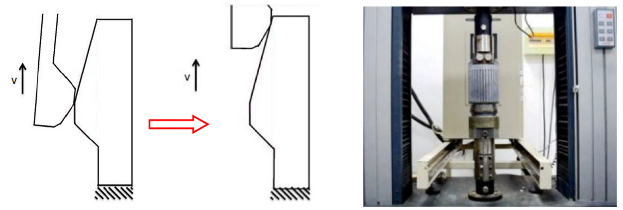
During unlocking, the finger lock is pulled by axial force
Force and displacement diagram of unlocking process. (a) Force analysis of unlocking process. (b) Displacement of unlocking process.
During locking, the finger lock receives axial force

Force and displacement diagram of locking process. (a) Force analysis of locking process. (b) Displacement of locking process.
Numerical simulation calculation
Constitutive model of wear
The force analysis of the lock mechanism is carried out. The contact tangential stress of the finger lock surface node can be obtained by calculation

By comparison

As shown in formula,
Finite element model
Finger lock is an axisymmetric structure. The loads and constraints are also axisymmetric. Therefore, only one of the contact fingers is extracted for analysis. The simplified process of the finite element model is as follows Figure 6 as shown. Because the contact surface is located in the convex part of the finger lock, the mesh density is increased in here. The 0.25 mm mesh is used here to improve accuracy. The 2 mm mesh is used in other positions.

Finger lock mesh. (a) Finger lock mesh. (b) Single contact finger mesh. (c) Finger lock convex mesh.
MSC.MARC is used in this paper, which has a strong ability to solve nonlinear problems and has the characteristics of high numerical stability, high accuracy, and fast convergence. According to the experimental requirements and related reference,
18
the wear coefficient is set as
40CrNi2Si2MoVA mechanical parameters.

30CrMnSiNi2A mechanical properties.

In real working conditions, the finger lock and the base work in the actuator cylinder of the landing gear. The base and the actuator cylinder are fixed. It means that the base cannot be displaced and twisted in the x, y, and z directions, So the degrees of freedom in the x, y, and z directions is constrained, such as shown in Figure 7. The constraint and load on the finger lock are obtained through the equivalent constraint transformation. During the entire unlocking process, the finger lock is displaced in the y direction and the displacement in the x and z directions is zero. The surface load with cyclic displacement is defined in the y direction of the upper surface of the finger lock. Cyclic displacement refers to the reciprocating movement of the type lock in the actuator cylinder in the y direction, such as shown in Figure 7.

Finger lock simulation boundary conditions. (a) Constraints of base. (b) Constraints of finger lock. (c) Finger lock load boundary condition.
Finally, the displacement control of the finger lock is set. The single wear condition of the finger lock is: a tensile load is applied and it moves 40 mm in the positive direction of y. Then a compressive load is applied and it moves 40 mm in the negative direction of y. This process is repeated 500 cycles.
Finger lock wear simulation results
During the 500 unlocking cycles wear calculations, the wear occurred gradually.As shown in Figure 8, it is the wear cloud map of the 001 finger lock in different steps. When the finger lock is worn 200 cycles, 400 cycles, and 500 cycles, the contact surface will show different wear states. The severity of wear of finger lock is different in different steps.

Wear map of finger lock 001 at various steps. (a) No wear. (b) Wear 200 cycles. (c) Wear 400 cycles. (d) Wear 500 cycles.
As shown in Figure 8, it can be seen that the main wear position of the finger lock occurs at the convex position where the inner surface of the lower part of the finger lock and the base contact, while the other parts of the finger lock do not have obvious wear. It has been worn 200 cycles, 400 cycles, 500 cycles, the different wear cloud maps show a gradual change of law. With the increase of the number of locking cycles, the outer edge of the contact surface will first wear, and the entire contact process is a line contact process. The number of cycles continues to increase, and the range of wear of the finger lock will gradually increase. From the final cloud map, it can be observed that the most severely worn position occurs on the convex lower edge of the finger lock. As shown in Figure 25, it is the final wear cloud map of each finger type for 001, 003, 009, 013, 017, 019, 021.
Wear verification experiment
Experiment introduction
The finger lock wear test was performed on an electric tensile and compression testing machine, which is electronic experimental machine of SANS. During the experiment, the finger lock and the base were connected to the upper and lower loading ends of the test machine respectively. The upper base is movable and the lower base is fixed. The control software of SANS sets the test parameters. The tensile force is positive and the compression force is negative. Set the loading speed not to exceed 100 N/s. The SANS electronic experimental machine and its data acquisition control interface are shown in Figure 9.
The SANS electronic experimental machine and its data acquisition control interface. (a) The SANS electronic experimental machine. (b) The control interface.
The assembly diagram of the finger lock in the experiment is shown in Figure 10. All types of finger locks are shown in Figure 11.

Assembly drawing of finger lock in experiment. (a) CAD assembly diagram. (b) Physical diagram.
All types of finger lock.
This experiment mainly consists of three parts: (1) the unlocking-locking experiment when it is not worn, (2) the 500 wear cycles experiment, and (3) the unlocking-locking experiment after wear.
Unlocking-locking experiment in the unworn state: Control the loading equipment to move the finger lock upward by 40 mm, and then return the original path to the initial position of 0 mm to complete the Unlocking-locking. The lifting process is the unlocking process and the return process is the locking process. In the experiment, the axial force data of this process is recorded.
500 wear cycles: Control the loading equipment to repeat (1) process 500 cycles.
Unlocking-locking test after wear: After the finger lock has completed 500 wear tests, clean up the surface debris of the test piece and fixture, and perform the Unlocking-locking test again according to the method (1), and record the axial force data during experimental process.
Force analysis of the unlocking-locking process
As shown in Figure 12, the curve of the axial force of the finger lock during a unlocking in the experiment. This curve is mainly generated by the axial component of the normal pressure and tangential friction. The wear process of the finger lock is divided into two according to unlocking and locking. The unlocking process is first pulling and then pressing, and the locking process is first pressing and then pulling. The curves of the unlocking and locking processes are clearly divided into four segments, namely phase1, phase2, phase3, and phase4, as shown in Figure 12.
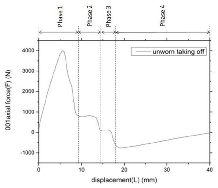
Phase diagram of axial force.
Take the unlocking process as an example, such as Figure 12 as shown. In phase1, the axial force increases rapidly and reaches the maximum value of the unlocking process. In this phase, the axial force is the tensile force, and the value is a positive number. The movement position of the corresponding finger lock is as shown in Figure 13.

Phase1.
In phase2, the axial force will become smaller and maintain a relatively constant value. In this phase, the axial force is still the pulling force. The movement position of the corresponding finger lock is as shown in Figure 14.

Phase2.
In phase 3, due to the tendency of elastic deformation to rebound, in this process, the axial force that needs to be provided will continue to decrease and maintain a constant value. At this time, friction is the main source, so it is still overcoming friction in this process. The axial force is still pulling force and the value is positive. The movement position of the corresponding finger lock is shown in Figure 15.

Phase3.
In phase4, since the elastic rebound starts and the component of the axial force caused by the rebound is far greater than the component provided by the friction, the axial force in this process is pressure and the value is negative. Minimum value of axial force in this phase during the unlocking process is reached, and the absolute value decreases linearly and gradually until it reaches zero. The movement position of the corresponding finger lock is as shown in Figure 16.
Phase4.
The locking process corresponds to and is exactly the opposite of the unlocking process.
Analyze the influence of design parameters
After the experiment is completed, the unlocking-locking axial force curve of the finger lock with these various design parameters can be obtained, such as shown in Figures 17–23. The abscissa indicates the displacement of the process; the ordinate indicates the axial force of the finger lock. The tensile force is positive and the compressive force is negative. The finger lock for each design parameter is made as two figures. There are four curves in each figure, which correspond to the unworn experimental process, worn experimental process, unworn simulation process, and worn simulation process of the finger lock. Meanwhile, the maximum unlocking force before and after the wear of the finger locks is different, such as shown in Table 6.

Comparative analysis of experimental and simulation data of 001 axial force. (a) 001 unlocking process. (b) 001 locking process.

Comparative analysis of experimental and simulation data of 003 axial force. (a) 003 unlocking process. (b) 003 locking process.
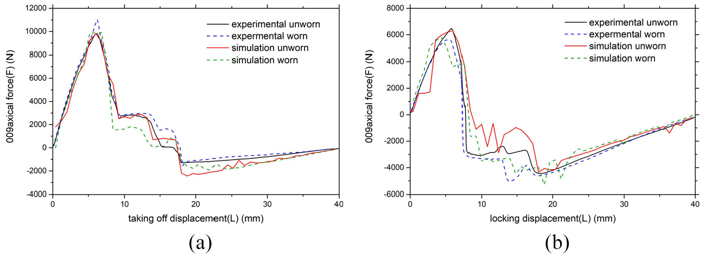
Comparative analysis of experimental and simulation data of 009 axial force. (a) 009 unlocking process. (b) 009 locking process.

Comparative analysis of experimental and simulation data of 013 axial force. (a) 013 unlocking process. (b) 013 locking process.

Comparative analysis of experimental and simulation data of 017 axial force. (a) 017 unlocking process. (b) 017 locking process.

Comparative analysis of experimental and simulation data of 019 axial force. (a) 019 Unlocking process. (b) 019 locking process.

Comparative analysis of experimental and simulation data of 021 axial force. (a) 021 unlocking process. (b) 021 locking process.
Table of wear value and unlocking axial force of each finger lock.

As shown in Figure 17, the simulation and experimental results of 001 are consistent according to the general trend. The maximum values of axial force are basically the same and consistent according to Table 6. After 500 unlocking cyckes, the contact surface of 001 becomes large and rough due to adhesive wear, which causes the friction coefficent change and the maximum unlocking force of each finger lock to become larger. Observe the four phases, phase1 and phase4 have a higher degree of fit, meanwhile phase2 and phase3 numerical calculations havs some differences from the experimental results. The main reason is that in phase 1 and phase 4 fingers in contact with the base changes less, and the axial force changes are simpler, so the wear algorithm is more accurate. In phase 2 and phase 3 fingers and the base contact shape changes drastically, and the axial force also oscillates multiple times. It is very difficult to simulate the contact load and wear with finite element, so the simulation data at this time will be different from the experimental data.
As shown in Figure 18, comparing 001 and 003, it can be known that the material of the 003 finger lock is different from 001. The 001 maximum unlocking force after wear is 4018.9N, and the 003 maximum unlocking force after wear is 4248.7N. Material changes have less effect on unlocking force after wear. It is because that the young’s modulus of the two materials changes little. Therefore, it can be known that when the change of material parameters is small, the change of unlocking force is also small.
As shown in Figure 19, comparing 001 and 009, it can be known that the length of the 009 finger lock is 75% of the length of 001, and the 009 maximum unlocking force is 2.46 times of 001; the 009 maximum unlocking force becomes larger after wear, changing from 9828.7N to 11017.8N; the length of the lock is inversely proportional to the unlocking force. It is because the finger lock will have pure bending deformation when unlocking. According to the deflection equation of pure bending, when the deflection is constant, the unlocking force is inversely proportional to L. Therefore, smaller L will lead to larger unlocking force.
As shown in Figure 20, comparing 001 and 013, it can be known that 013 finger lock diameter parameters
As shown in Figure 21, comparing 001 and 017, it can be known that 017 finger lock diameter parameters
As shown in Figure 22, comparing 001 and 019, it can be known that the number of finger n is reduced from 36 of 001 to 24 of 019, and the 019 maximum unlocking force is 1.13 times of 001; the 019 maximum unlocking force after wear is increased, from 4510.1N to 4745.9N. The number of finger n is inversely proportional to the unlocking force. This is because the finger lock will have pure bending deformation when unlocking. The decrease of n will lead to the increase of inertia moment of finger lock. According to the deflection equation of pure bending, when the deflection is constant, the unlocking force is proportional to the moment of inertia. Therefore, when n becomes smaller, the unlocking force becomes larger.
As shown in Figure 20, comparing 001 and 021, it can be known that the angle of the 021 finger lock changed from 45° of 001 to 60°, and the 021 maximum unlocking force was 1.68 times of 001; the 021 maximum unlocking force became larger after wear, from 6427.7N to 6799.2N. Finger lock angle parameter is proportional to unlocking force. This is because when the angle increases, the horizontal component of the contact force between the finger lock and the base decreases. At this time, only when the axial unlocking force becomes larger can it reach the value required by the original unlocking. Therefore, the unlocking force becomes larger.
In a word, in the phase with no wear, the maximum and minimum values of the numerical simulation curve and the experimental curve are basically the same. Among the four phases, except for phase 2, the overall consistency is good; after wear, the numerical simulation curve and the experimental curve also maintain good consistency, the finite element model has high reliability.
Comparative analysis of finger lock wear physical and simulation map
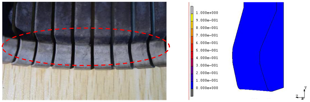
As shown in Figure 24, it is the unworn physical and simulation map of the 001 finger lock. In Figure 25, it is the physical and simulation maps of the worn of the finger lock after 500 unlocking cycles. Compare Figures 24 and 25. It can be known that the finger locks after 500 unlocking cycles, the convex parts of the finger locks show small wear marks horizontal to the direction of movement. The worn surface is brighter. Brighter means the greater amount of wear. It can be seen from the observation that the upper and lower chamfers of the finger lock convexity show obvious brightness, and the worn boundary is obvious. Compared to other positions, the plane between the upper and lower chamfers is obvious.
Unworn 001 finger lock physical and simulation map.
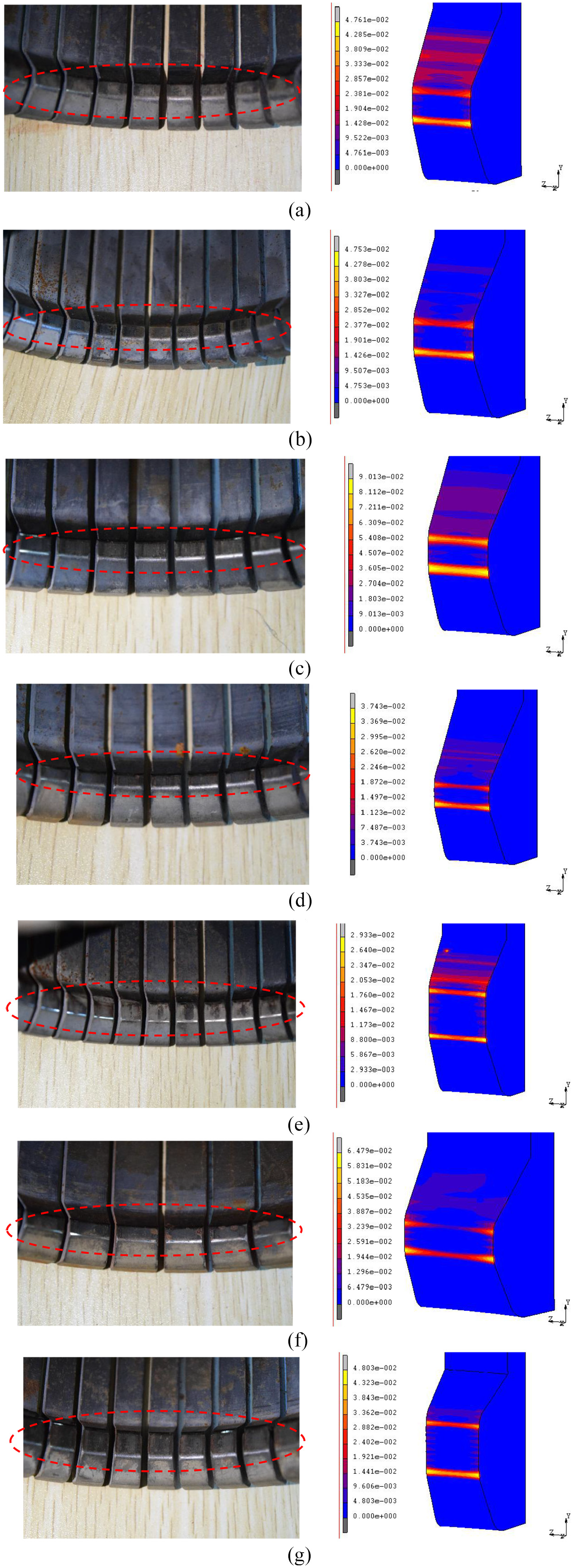
Physical and simulation map of wear of each finger lock. (a) 001 worn physical and simulation map. (b) 003 worn physical and simulation map. (c) 009 worn physical and simulation map. (d) 013 worn physical and simulation map. (e) 017 worn physical and simulation map. (f) 019 worn physical and simulation map. (g) 021 worn physical and simulation map.
The comparison between the physical map and the simulated cloud map found that the basic contour of the wear position of the finger lock is consistent. The wear cloud map calculated by numerical simulation has a predictive effect on the surface wear state after 500 unlocking cycles in the experiment. At the same time, wear debris will be generated in the experiment. Simulation calculations currently cannot simulate the generation of wear debris.
By observing Figure 25, it can be seen that the final wear cloud maps of different types of finger locks have their own characteristics. The common feature is that the maximum position of wear of each type of finger lock is located at the lower chamfer of the finger lock convexity and the base contact convexity. At this position, the entire chamfer is worn. For the same finger lock, the loss rate at this position is basically the same; At the plane between the upper and lower chamfers, each types of finger lock was partially worn on the left and right sides of the plane, and showed a tooth-like distribution; the upper chamfer of the each finger lock is another location where large wear occurs, but the wear here shows severe wear at both ends and less wear in middle; the convex upper bevel of the finger lock is worn, but the wear cloud maps of different types of finger locks are different here.
Conclusions
This paper studies the finger locks in the landing gear actuator (six different key parameters: the material of the finger lock, the length L of the finger lock, the diameter of the finger lock ∅1 and ∅2, and the number of petal locks n, The angle of the fingertip Θ), the numerical simulation and experimental verification of the unlocking force are completed, and the following conclusions can be obtained:
Through the comparison of the finger locks of various models and 001 finger lock, it can be known that when the materials property difference is small, the materials have a small effect on the unlocking force. The length of the finger lock L is inversely proportional to the unlocking force. The diameters ∅1 and ∅2 of the finger locks are inversely proportional to the unlocking force, the number of petals n of the finger lock is inversely proportional to the unlocking force, and the angle Θ of the fingertip is proportional to the unlocking force.
Finite element simulation based on the Archard wear theory reveals the detailed process of the entire wear of the finger lock. It can be observed that the maximum wear position occurs at the lower chamfer of the finger lock convexity. Therefore, the position where the wear occurs and its trend of changes provides a reference for the design of finger locks in the future.
It can be known from the wear experiment that the contact surfaces of seven types of finger locks are worn after 500 unlocking cycles, but the impact on the maximum axial force is small. The wear has affected the value of axial force in phase2 and phase3, making it larger. After 500 unlocking cycles, the finger lock is still in a normal working state.
From the comparison between the numerical simulation results and the experimental results, it can be seen that the simulation and experiment have good consistency, and the maximum axial force of the experiment and simulation is close. Therefore, the finite element numerical simulation method can be better to predict the change of axial force after the finger lock is worn. The Archard theory is used to calculate the wear of this type of non-linear contact, which has high reliability.
In a word, this paper obtains the changing rules of the six design parameters of finger lock in one working cycle (500 unlocking cycles), which provides reference and basis for the design of finger lock in the future. However, the experiments designed in this paper are all vertical, the real landing gear actuator is not completely vertical in the working state. If the weight of finger lock itself is taken into account, the uneven distribution of force may lead to biased wear, which can be further studied in the future.
Footnotes
Declaration of conflicting interests
The author(s) declared no potential conflicts of interest with respect to the research, authorship, and/or publication of this article.
Funding
The author(s) received no financial support for the research, authorship, and/or publication of this article.