
Abstract
This paper presents a new class of flexure hinges, namely, conic-V-shaped flexure hinges (CFHs), which can be used as a generalized model for flexure hinges with profiles such as parabolic-V-shape, elliptical-V-shape, and hyperbolic-V-shape. Compliance and precision equations for the CFHs were derived as a set of nonlinear equations using Castigliano’s second theorem. The parameters of the nonlinear equations inputted to the compliance and precision matrices were based on the generalized equations used for conic curves in polar coordinates. Furthermore, the compliance equations were verified by means of finite element analysis and experiments. The errors in the finite element and experimental results were within 10% and 8% compared to the analytical results, respectively. Finally, the effects of dimensional parameters on the analytical model could be effectively analyzed by numerical simulations and comparisons.
Introduction
Owing to small size, high sensitivity, monolithic manufacturing process, zero backlash and friction, lack of lubrication, smooth motion, and virtually-infinite resolution of flexure hinges, they are widely used in compliant mechanisms for micro/nano positioning, ultra-precise machining and manufacturing, and automated biological cell manipulation; other applications are in micro-positioning stages, scanning electron microscopy, X-ray lithography, and piezoelectric actuators.1–6
Flexure hinges with various cutout profiles have been proposed and studied.7–12 In 1965, Paros and Weisbord 13 proposed circular flexure hinges and derived simplified design equations, including a complete theoretical analysis. Smith et al. 14 derived a compliance matrix for corner-filleted and shallow-notch elliptical flexure hinges and constructed a compliance calculation model. Chen et al. 15 introduced the centrifugal angle as the integral variable to derive a compliance equation for elliptical flexure hinges. Lobontiu et al. 16 deduced compliance equations for parabolic and hyperbolic flexure hinges. Wang et al. 17 proposed a novel class of exponent-sine-shaped flexure hinges with asymmetric structures and higher motion accuracy. Li et al. 18 derived closed-form compliance equations for a power-function-shaped flexure hinge and investigated its motion accuracy. Lobontiu et al. 19 presented an analytical approach to corner-filleted flexure hinges. Yong et al. 20 analyzed the comparison of various compliance/stiffness equations of circular flexure hinges with FEA results. Hsiao et al. 21 propose a novel flexure hinge with 3° of freedom in which the motions are restricted in the same plane. Liu et al. 22 designed and analyzed a new kind of flexure hinge obtained by using a topology optimization approach, namely, a quasi-V-shaped flexure hinge.
In the design of a flexure hinge, two main aspects need to be considered: the profile type and the parameter design.23,24 A flexure hinge is typically designed by selecting a certain type of profile based on the designer’s experience. The corresponding design equations are used to design the parameters. The two aspects are theoretically independent of each other, and there is no clear basis for selecting the profile type. Hence, generalized models for flexure hinges with various cutout profiles have been proposed. For example, Vallance et al. 25 presented a unified geometric model for designing flexure hinges; the model is suitable for representing an entire class of conic-section hinges using quadratic rational Bézier curves. Chen et al. 26 incorporated elliptical arc, parabolic, and hyperbolic profiles in a generalized conic flexure hinge model and deduced all the elements in the compliance matrix. Tian et al.27,28 presented filleted V-shaped flexure hinges (FVFHs), with profiles ranging from leaf-shaped to circular, and derived closed-form compliance equations and motion accuracy equations.
This paper proposes a new class of flexure hinges called conic-V-shaped flexure hinges (CFHs), in order to develop a generalized flexure hinge model and to improve the design of flexure hinges. The generalized flexure hinge model encompasses elliptical-V-shaped, parabolic-V-shaped, and hyperbolic-V-shaped. Figure 1 shows the 3D geometry of a CFH. The geometric parameters include the cutout length l, minimum thickness t, cross-sectional width w, cutout depth c, and the angle φ between the tangent to the V-shaped curve and the x axis. The V-shaped curves are tangent to the conic curves. Compliance and precision equations were deduced for this class of CFHs for the geometric optimization design in polar coordinates. Stress equations were also derived for the stress concentration. Finally, the finite element analysis and experiments were conducted to verify the compliance and precision equations.

Schematic of a conic-V-shaped flexure hinge.
The generalized equation in polar coordinates
Figure 2 shows a conic curve along with its directrix and focus OF. In polar coordinates, the conic curve with focus OF as the origin can be expressed as

where p (>0) is the distance between the corresponding directrix and the focus, and e (>0) is the eccentricity, which can be expressed as

When e > 1, the conic curve is a hyperbola; when e = 1, it is a parabola; and when e < 1, it is an ellipse.

Conic curve represented in polar coordinates.
As shown in Figure 3(b), we assume that the entire notch of the CFH ranges from −θ n = −π/2 to θ n = π/2 (θ n is the maximum polar angle of the notch). The conic curve ranges from −θ m to θ m (θ m is the maximum polar angle of the conic curve). φ is the angle between the tangent to the V-shaped curve and the x axis. In this generalized model, e, p, φ, and t are the design parameters for the hinge cutouts. The equation for the tangents can be expressed as

where θ m can be calculated as

The notch length can be calculated as

Figure 3 shows the relationships among three different types of flexure hinges. For different values of θ m , φ, and e in a certain range, different cutout profiles of the flexure hinges can be obtained, such as elliptical-V-shape, parabolic-V-shape, hyperbolic-V-shape, leaf-shape, elliptical, parabolic, and hyperbolic. When φ = 0, the hinge is a leaf flexure hinge. When θm = π/2, the hinge is a conic flexure hinge (elliptical arc flexure hinge, parabolic flexure hinge, or hyperbolic flexure hinge). When π/2 > θm > 0, the hinge is a CFH (elliptical-V-shaped flexure hinge, parabolic-V-shaped flexure hinge, or hyperbolic-V-shaped flexure hinge). φ m is the angle between the tangent and the x axis when θ m = θ n = π/2 which can be calculated as:

Relationships of three flexure hinges: (a) θ m = 0, φ = 0, (b) 0 < θ m < θ n = π/2, 0 < φ < φ m , and (c) θ m = θ n = π/2, φ = φ m .
Compliance equations for conic-V-shaped flexure hinges
The notch area of the CFH is divided into countless cuboids vertically, and the height of a small bar dθ at position θ can be expressed as

where


As shown in Figure 3, the relationship between x and θ can be expressed as

Differentiating the above equation yields:

Compliance matrix
When the minimum thickness of a flexure hinge t is assumed to be much lower than the notch length l, the hinge can be considered a fixed free beam with 6° of freedom subjected to bending, axial loading, shearing, and torsion, as shown in Figure 1. The force acting on the hinge can be defined by

and the deformations of the hinge can be defined by

Accordingly, the following equation can be obtained

where

The compliance matrix is symmetric (αz/Fy = Δ y /Mz and αy/Fz = Δ z /My). Each factor in the compliance matrix is derived from the following beam theory.
Under an external load P, the elastic strain energy Vε of a flexure hinge can be used to compute the corresponding deformation Δ based on Castiglione’s second theorem:

The total strain energy is defined as follows:
where E is the Young’s modulus, G is the shear modulus, M is the bending moment, FN is the force along the x axis, FS is the shearing force, I is the cross-sectional moment of area, and A is the cross-sectional area. The shearing coefficient k is equal to 6/5 for beams with rectangular cross sections. 29
Compliance equations
Angular compliance about the z axis
The z axis is the input axis of the flexure hinge, and the angular compliance corresponding to the torque Mz can be expressed as

where Iz(θ) represents the moment of inertia at the cross-sectional area about the neutral axis at position θ.
The effect of Fy on αz is equal to its equivalent moment Fy[l/2 − ep sinθ/(1 + e cosθ)]. Therefore, the angular compliance corresponding to the force Fy can be calculated as

Angular compliance about the y axis
The angular compliance of the y axis corresponding to the torque My can be expressed as

The effect of Fz on αy is equal to its equivalent moment −Fz[l/2 − ep sinθ/(1 + e cosθ)]. Therefore, the angular compliance corresponding to the force Fz can be calculated as

Linear compliance along the z axis
Since the compliance matrix is symmetric, the linear compliance of the torque My along the z axis can be expressed as

The linear compliance of the force Fz along the z axis can be divided into two parts: a bending part (represented by Δbz/Fz) and a shearing part (represented by

The bending part can be calculated as

Therefore, the linear compliance along the z axis due to Fz can be expressed as

Linear compliance along the y axis
Considering the symmetry in the compliance matrix, we can express the linear compliance of the torque Mz along the y axis as

Based on the derivation of Δz/My, the linear compliance along the y axis due to Fy can be expressed as

Linear compliance along the x axis
The linear compliance along the x axis can be expressed as

Angular compliance about the x axis
Since each infinitesimal element in the flexure hinge model can be considered a rectangular beam, according to the approximate torsion equation given in Hearn’s book, 30 the angular compliance about the x axis can be expressed as

Precision equations for conic-V-shaped flexure hinges
To facilitate the analysis of the transmission precision of CFHs, the offset of the center point of the hinge profile (point S in Figure 3) is often used to characterize its transmission precision. By defining the offset of S as

we can obtain the relationship between the offset and the force vector as

where

The elements in the precision matrix are called precision factors.
In the precision matrix, the precision factors along the x axis can be given by

The precision factor corresponding to Mz along the y axis can be calculated as

and the precision factor corresponding to the force Fy can be obtained using
The precision factor corresponding to Mz along the z axis can be calculated as

the precision factor corresponding to force Fz is

The calculations of I1–I6 are shown in Appendix 2.
Verification of closed-form equations
Finite element verification
The compliance equations were verified using the finite element method. ANSYS was employed to calculate the compliance factors of several flexure hinge designs under static loading. We first designed a 3D finite element model in SolidWorks and generated hexahedral grids using the HyperMesh software meshing model. We then established quality point mass, created MPC units, set up the related attributes, and finally performed a grid file import analysis in ANSYS, where each hinge model was fixed at one end and loaded at the other end. Figure 4 shows one of the CFH models. Considering the accuracy and efficiency of the calculation, we set the number of grids to no less than 0.4 million.
Finite element model of a conic-V-shaped flexure hinge.
Table 1 lists the physical and geometrical parameters of the CFHs. The width (w) of the flexure hinges was 10 mm; the material was spring steel; the Young modulus was 2.07 × 10¹¹ N/m2; the shear modulus was 8.1 × 10¹⁰ N/m2. The calculation results, listed in Table 2, were obtained by programming the above closed-form equation.
Design examples of conic-V-shaped flexure hinges.

Comparison of compliance factors between theoretical results (denoted by C) and finite element results (denoted by F).

Owing to the symmetry in the compliance matrix, only Δ x /Fx, Δ y /Fy, Δ z /Fz, αy/My, αz/Mz, αx/Mx, Δ y /Mz, and Δ z /My were verified. The data in Table 2 show that the error in the theoretical calculation and finite element analysis is within 10%, thus confirming the correctness and rationality of the theoretical model.
Experimental verification
To investigate the performance of the proposed generalized model, experimental tests were carried out on four CFH samples. Figure 5 shows the diagram of a sample. In Figure 6, one of the four samples, made of spring steel with an elastic modulus E = 2.07 × 10¹¹ Pa and a shear modulus G = 8.1 × 10¹⁰ N/m2, was machined using wire electrical discharge machining with a low-traveling speed technology.
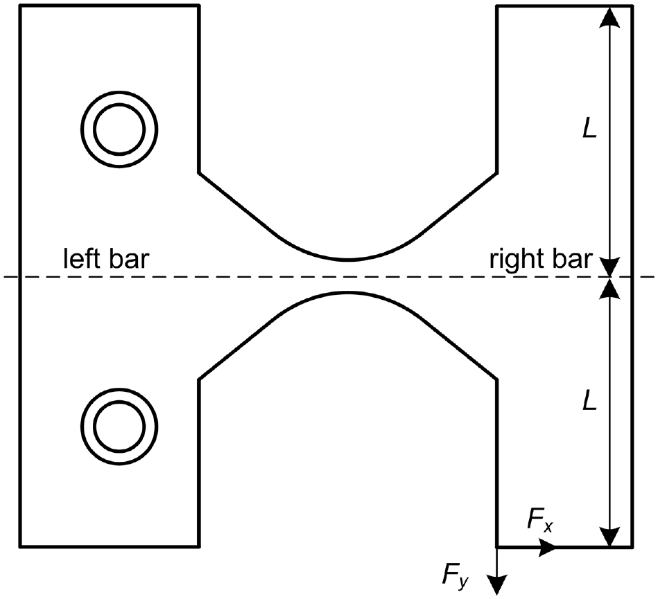
Diagram of a flexure hinge sample.

Flexure hinge sample (e = 0.4, p = 12.1 mm, w = 10 mm, t = 1 mm, φ = π/6).
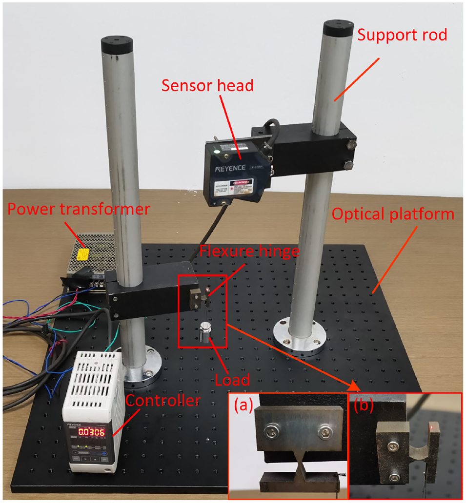
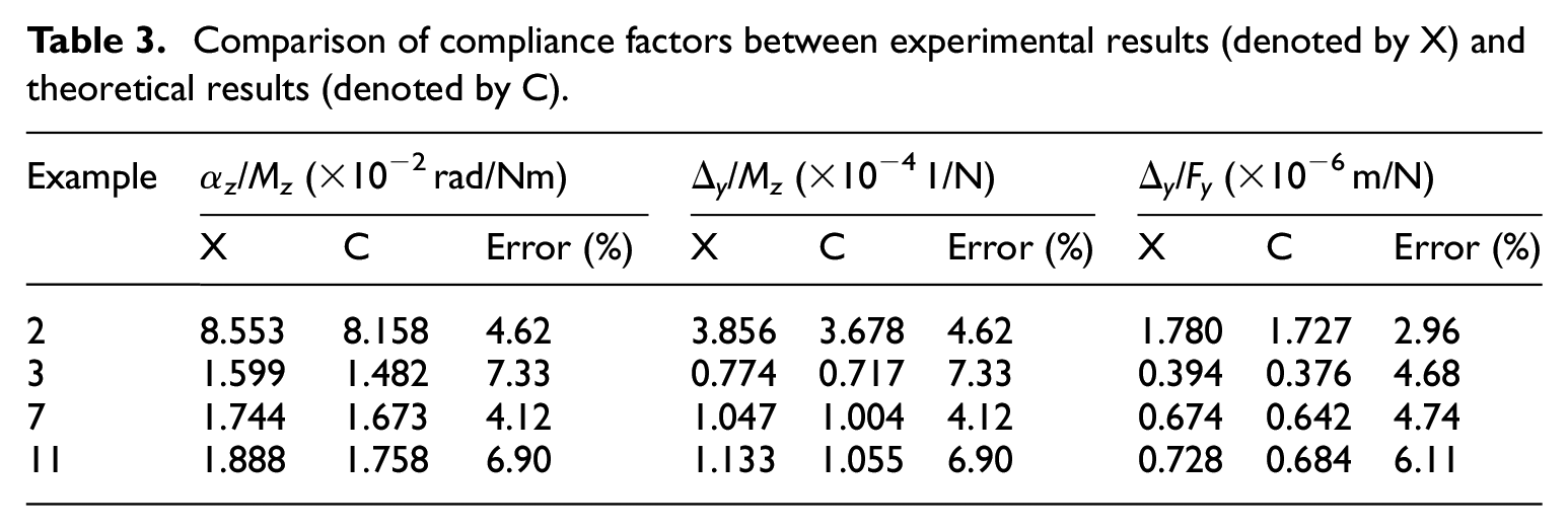
Figure 7 shows the experimental setup, including a laser displacement sensor (KEYENCE® LK-G155H with a 0.5 μm resolution), a power transformer, an optical platform, two support rods, four flexure hinge samples, and some standard weights (ranging from 0.01 to 0.5 kg). The support rods were mounted on the optical platform. The sensor head was fixed on one support rod using a holder. One end of the hinge sample was fixed on the other support rod using a holder, and the other end of the hinge sample was loaded with weights. As shown in Figure 7(a), a force Fx is applied, including a moment Mz = FxL. When the displacement of the right bar is measured, the compliance factor Δ y /Mz can be calculated. Because the deformation is small enough, the angle displacement can be considered αz ≈ tanαz and the compliance factor αz/Mz also can be calculated. In Figure 7(b), the displacement of the right bar can be measured under the force Fy. Thus, the compliance factor Δ y /Fy can be obtained. The flexure hinges are loaded with ten different loads. The force is evaluated by placing masses ranging from 50 to 500 g. The mass difference between adjacent weights is 50 grams. The compliance factors are calculated as average values. The experimental results are shown in the following table. Table 3 lists the experimental results. The results show that the experimental measurements are within an error of 8% compared to the analytical results.
Experimental setups for the evaluations of: (a) αz/Mz and Δ y /Mz and (b) Δ y /Fy.
Comparison of compliance factors between experimental results (denoted by X) and theoretical results (denoted by C).
The following are some of the potential factors that may have caused an uncertainty in the experiments: (1) The difference between the designed samples and processed samples, (2) The accuracy of the measurement system, (3) The difference between the marked value and the actual value of weights.
Numerical simulations and comparisons
To investigate the effects of dimensional parameters on the analytical model, numerical simulations and comparisons are essential. In the generalized model for CFHs, the design parameters are e, p, w, t, and φ. The cutout profile of a CFH is determined by e, p, and φ, whereas the structural characteristics of a flexure hinge are determined by w and t. To investigate the influences of the profile, w, t, and φ were set to 10 mm, 0.5 mm, and π/6, respectively, while both e and p were varied from 0.1 to 1.9. Figure 8 shows the variations in the compliance factors with respect to e and p. Next, we set e, p, w, and t as 0.6, 5.33 mm, 10 mm, and 0.5 mm, respectively, while φ was varied from 0 to 50 deg. Figure 9 shows the variations in the compliance factors with respect to φ. To investigate the effects of the structural characteristics, e, p, and φ were set to 0.6, 5.33 mm, and π/6, respectively, while w and t were varied from 6 to 15 mm and 0.1 to 1 mm, respectively. Figure 10 shows the variations in the compliance factors with respect to w and t.
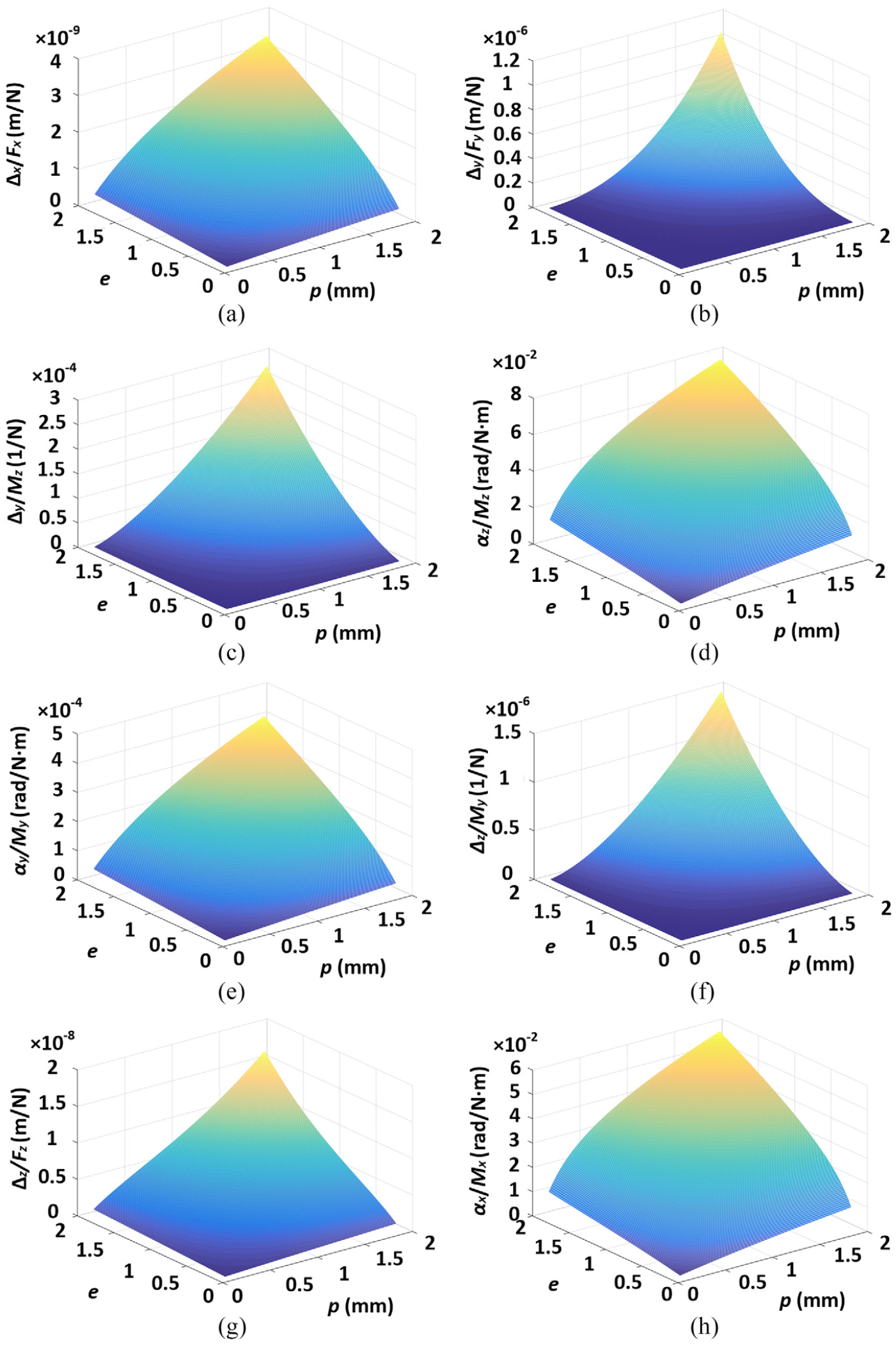
Variations in the compliance factors of CFHs with respect to e and p: (a) Δ x /Fx, (b) Δ y /Fy, (c) Δ y /Mz, (d) αz/Mz, (e) αy/My, (f) Δ z /My, (g) Δ z /Fz, and (h) αx/Mx.

Variations in the compliance factors of CFHs with respect to φ: (a) Δ x /Fx, (b) Δ y /Fy, (c) Δ y /Mz, (d) αz/Mz, (e) αy/My, (f) Δ z /My, (g) Δ z /Fz, and (h) αx/Mx.
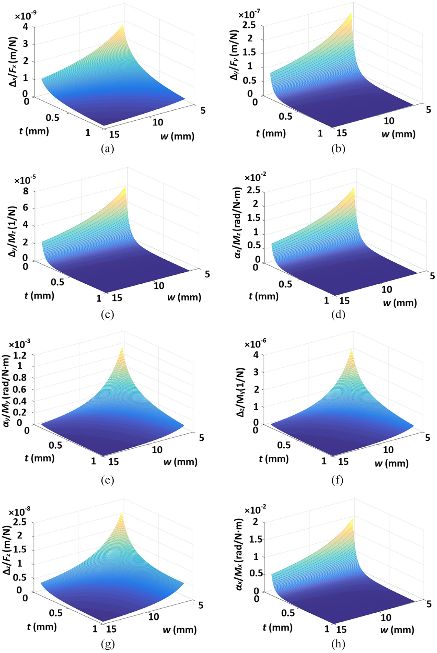
Variations in the compliance factors of CFHs with respect to w and t: (a) Δ x /Fx, (b) Δ y /Fy, (c) Δ y /Mz, (d) αz/Mz, (e) αy/My, (f) Δ z /My, (g) Δ z /Fz, and (h) αx/Mx.
The compliance factors nonlinearly increase with increasing eccentricity e and increasing distance p between the corresponding directrix and the focus, as shown in Figure 8. Moreover, the variation sensitivities of Δx/Fx, αz/Mz, αy/My, and αx/Mx to e and p decrease, while the variation sensitivities of Δy/Fy, Δy/Mz, Δz/My, and Δz/Fz to e and p increase. The eccentricity e and the distance p between the corresponding directrix and the focus have largely the same influence on the performances of the conic-V-shaped flexure hinges.
Figure 9 shows that the compliance factors Δx/Fx, Δy/Fy, Δy/Mz, αz/Mz, αy/My, Δz/My, Δz/Fz, and αx/Mx nonlinearly decrease with increasing angle φ, while their variation sensitivities to the angle φ decrease.
As shown in Figure 10, the compliance factors nonlinearly decrease with increasing cross-sectional width w and increasing minimum thickness t, while their variation sensitivities to cross-sectional width w and minimum thickness t decrease. The parameter t has a more significant influence on the compliance factors Δy/Fy, Δy/Mz, αz/Mz, and αx/Mx than the cross-sectional width w.
Conclusion
This paper presents a new class of flexure hinges, namely conic-V-shaped flexure hinges, which can be used as a generalized flexure hinge model for elliptical-V-shaped, parabolic-V-shaped, and hyperbolic-V-shaped. The following conclusions can be summarized:
The compliance and precision equations for the CFHs were derived using Castigliano’s second theorem. The factors in the compliance equations were verified by finite element analysis and experimental measurements. The errors in the finite element analysis and experimental results were within 10% and 8% compared to the analytical results, respectively. This demonstrates the practicality of the compliance and precision equations derived for CFHs.
Based on the analytical results, numerical simulations and comparisons are made to investigate the effects of dimensional parameters on the analytical model. The results showed that the compliance factors increased with the increase of the eccentricity e and the distance between the corresponding directrix and the focus p, but decreased with the increase of the angle φ, the minimum thickness t, and the cross-sectional width w.
Footnotes
Appendix 1
Appendix 2
I1–I6 are used to calculated factors in the compliance and precision matrixes as shown in sections 3 and 4. And I1-I6 can be expressed as
Declaration of conflicting interests
The author(s) declared no potential conflicts of interest with respect to the research, authorship, and/or publication of this article.
Funding
The author(s) disclosed receipt of the following financial support for the research, authorship, and/or publication of this article: This work was supported by the National Natural Science Foundation of China (51705378 and 51875418), Hubei Provincial Natural Science Foundation of China (2018CFB757), Postdoctoral Sustentation Fund of China (2017M622532), Youth Fund Project for the State Key Laboratory of Refractories and Metallurgy (2018QN15).