
Abstract
Gradient ceramic tools (GCT) have a wide range of potential applications due to their excellent thermodynamic properties and cost-effectiveness. Material distribution is a key factor affecting the performance of GCT. Currently, the material distribution status lacks adaptability with existing forming methods, which limits the further application of GCT. Additive manufacturing allows for the free forming of GCT, but there are issues of time-consuming and inaccurate data in optimizing the thermodynamic performance of GCT through experimental measurements. Therefore, in the context of additive manufacturing, a center-symmetric gradient (CSG) ceramic tool was designed using thermodynamic coupling simulation, and its thermodynamic coupling mechanism was subsequently examined. Firstly, the heat conduction theory is utilized to establish the heat conduction model of CSG ceramic tool. Subsequently, the thermal stress field is analyzed and simulated. The results indicate that the thermal stress accumulates during the initial stage I of CSG as the thermal shock time progresses. In the subsequent stage II of thermal shock duration, the maximum thermal stress point is located far from the tool tip, and all eight cutting edges are equally effective. Moving on to stage III, which is characterized by zero thermal load, the tool surface temperature decreases rapidly. However, even when the temperature field gradient difference approaches zero, residual thermal stress still persists. This residual stress is identified as the root cause of the tool material performance failure. Based on the thermodynamic coupling mechanism of CSG and additive manufacturing ideas, the three layers CSG and five layers CSG are designed using the finite element method. In sum, this study establishes a theoretical foundation for the design of GCT and serves as a reference for the development of functional devices or multimaterial structures.
Keywords
Introduction
The rapid development of the manufacturing industry has higher and higher requirements for tool materials. The gradient ceramic tool (GCT) shows great potential for application in high-speed cutting and dry cutting due to its exceptional properties such as high hardness, high temperature resistance, and corrosion resistance. Conventional GCT limits the number of effective cutting edges and reduces tool life. A center-symmetric gradient (CSG) ceramic tool by additive manufacturing process of material extrusion and photo-polymerization combination (MEX-PPM) 1 is expected to improve the application performance of the GCT because the material distribution is adaptability with the cutting thermal stress gradient. Specifically, the MEX-PPM process enables precise control over the internal stress state, allowing the fabrication of structures with compressive stress on the surface (to resist wear and fracture) while maintaining tensile stress internally (to absorb energy and prevent catastrophic failure). However, the thermal stress mechanism of the GCT is still unclear, and it is difficult to measure directly through experiments. Finite element simulation technology is a kind of engineering analysis method based on numerical calculation, which can simulate complex physical phenomena and engineering problems, and provide strong support for the optimization design of tool materials.
The reasonable gradient of gradient ceramic cutting tools could be formed by controlling the composition distribution of materials, and the favorable residual stress distribution inside the tool was generated, offsetting the external load stress during cutting,2,3 so as to a decrease of the surface thermal conductivity and high thermal expansion coefficient, and they were not easily damaged.4,5 The tool life of steel materials were much larger than that of Al2O3 materials, and it exhibited better self-sharpening ability, which could still perform normal cutting after chipping.6–8
At present, the existing gradient ceramic cutting tools were mostly axisymmetric structures,9–12 and the secondary shearing could achieve gradient materials that consistent to the heat distribution of cutting,13,14 while it would sacrifice the number of effective cutting edges used. Although the structure of centrally symmetric gradient was conductive to the number of cutting edges, there were few reports related to this type of ceramic cutting tool. Nowadays, finite element method (FEM) had been widely used in the research of the engineering materials, mechanics, thermodynamics,15–18 etc. The gradient tool materials could be designed according to the model of thermal residual stress, and the hard alloys was used to gradient Al2O3-based ceramics. 19 FEM was used to perform the linear elastic analysis of residual thermal stress in the preparation process of Al2O3-Ti, optimizing gradient parameters, and reducing residual thermal stress, 20 and it was also adopted to analyze the thermal stress generated by TiC/Ni3Al, MgO/Ni, PSZ/Mo, etc., under the assumption of the inelastic during use. By adjusting the material composition distribution index, the maximum thermal stress was alleviated and its position was adjusted. 21 The performance of gradient ceramic cutting tools had been much improved, while the design cycle has been shortened through FEM analysis. However, the theoretical model and thermal stress characteristics for the center-symmetric gradient ceramic tool had not been studied.
The distribution of material composition is a key factor that affects the performance of gradient ceramic cutting tools, making tool material design, and preparation particularly important. In the context of additive manufacturing, this study concentrates on optimizing the CSG through a thermodynamic coupling simulation method, and explores the thermodynamic coupling mechanism. This study establishes a theoretical basis for the design of GCT and offer valuable insights for the development of functional devices or multimaterial structures.
Theoretical model
Heat conduction equation
Cutting heat would bring an increase of temperature on the tool, which had caused a swell and thermal stress of the internal material, and the acceleration of tool wear. Based on the types of stress, the internal friction zone at the front, rear cutting surfaces, and the cutting edge of the tool were subjected to tensile stress during cutting, especially for the distance of 2 to 2.5 times from the cutting edge, the tensile stress is greater, while the rest of area is mainly subjected to compressive stress. The gradient ceramic tool materials with the counteracting or transfering thermal stress ability should be designed and prepared. Moreover, ceramic cutting tools exhibited good compressive strength in their inherent material properties, while that of their tensile strength was weak,22,23 and their wear and damage mainly occur in the cutting area of the tool surface during cutting. Hence, a gradient ceramic tool with a material composition that varies symmetrically from the center to the periphery (referred to as the center-symmetric gradient ceramic tool, CSG) was proposed. The surface of the tool had compressive stress, and the remaining area had tensile stress (Figure 1).
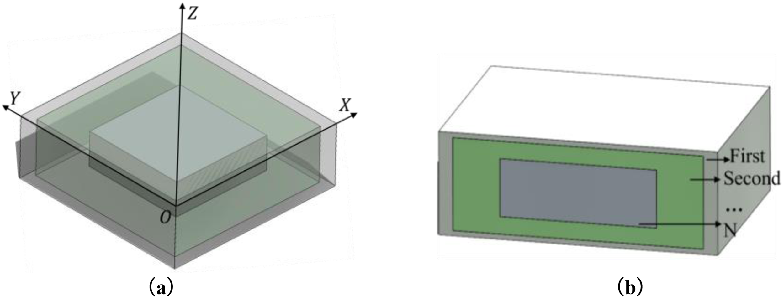
Centrally symmetric gradient ceramic tool model with multimaterial structure: (a) integral structure and (b) sectional structure.
Figure 1 shows a CSG model, whose mechanical properties gradually change with the material composition from the surface to the interior. It has eight effective cutting edges, greatly improving the overall service life of the gradient ceramic tool. This work takes the three-layer gradient structure as an example to construct a thermal stress model for CSG. The material and properties of CSG vary along the X, Y, and Z axes, and their two-dimensional planar structure and boundary conditions are shown in Figure 2. In order to simplify the solid heat conduction model of cutting tools, the inner plane structure of the first quadrant is selected as the research object, as shown in Figure 3.

Plate structure.

Simplified model.
In Figures 2 and 3, d, b, g, and w represent half of the dimensions of the tool core and surface material structure in the X, Y, and Z directions, respectively. Assuming the CSG is placed in an environment with a temperature of Ts, the initial temperature of the tool is T0, and the convective heat transfer coefficient between the tool material and the environment is h. In this environment, a center-symmetric gradient structure will undergo two-dimensional transient heat conduction, where the temperature is a function of radial, axial, and time. The mathematical description of the third type boundary condition heat conduction problem for this solid is as follows:
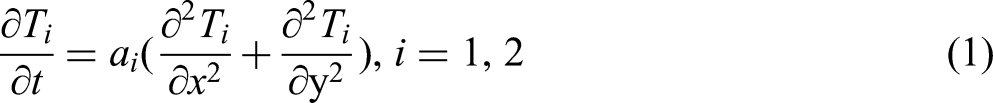

where Ti is the temperature, ai the thermal conductivity, λi the thermal diffusivity, Ci the heat capacity, ρi the density, and i the number of gradient layer. If i = 1 represents the first layer (core) material and i = 2 represents the second layer (surface) material, then the solid heat conduction equation of the center symmetric gradient ceramic cutting tool can be written as:


At the top boundary, the temperature gradient are set as:


At the internal continuous layer boundary, the temperature gradient are set as:


The initial condition for the temperature gradient is set as:

Analytical equation for thermal stress
In order to solve the analytical equations of the temperature field and stress field of the CSG conveniently, the dimension of equations (1) to (11) is unified.


The heat conduction equation of CSG can be written as:


At the top boundary, the temperature gradients are set as:


At the internal continuous layer boundary, the temperature gradients are set as:


The initial condition for the temperature gradient is set as:

After normalization, the heat conduction equation can be separated into:


Collation can be obtained:
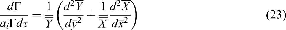
Let both sides of equation (23) equal a nonpositive number, then the left side of equation (23) can be written as:

The left side of equation (23) can be written as:

Make both sides of equation (25) equal to −F2, and solve formulas 24 and 25 to get:

where A, A1, A2, B1, and B2 are integral constants, γ2 = F2−β2.
Applying analytical equations (26) to (21) gives the following result:

According to the boundary conditions of the heat conduction equation, it can be solved as follows: A1 = 0, A2 = 0. Then equation 27 can be written as follows:

Substituting equation (28) into equation (15) reveals that the transcendental equation for F has n solutions, whereas substituting equation (27) into equation (17) reveals that the transcendental equation for γ has m solutions. Consequently, the temperature field model for gradient ceramic cutting tools can be expressed as:


For the core, according to the initial conditions can be:

For the core, according to the initial conditions can be:

For the second material, according to the initial conditions can be:

For the core, according to the initial conditions can be:

According to the center symmetry of the gradient ceramic tool, it expands and expands freely during the thermal shock process. According to Hooke's law, the transient thermal stress field model changing with the temperature field can be obtained as follows:


Finite element analysis
Simulation model and conditions
The influence of thermal radiation is disregarded in the thermodynamic couple simulation analysis of gradient ceramic tool materials. Under quasi-steady state conditions, it is assumed that the heated area satisfies the thermodynamic equilibrium equation. The main and secondary rear tool surfaces are considered adiabatic, while the contact surface between the front tool and the tool body represents convective heat transfer boundary. The boundary conditions set in the simulation are illustrated in Figure 4(a). A finer grid is employed in areas close to the tip where heat source density is high, as depicted in Figure 4(b). For thermal shock testing purposes, a point heat source loading mode is utilized during simulation, as shown in Figure 4(c).

Thermal shock test of tools: (a) boundary conditions; (b) meshing; and (c) heat source loading method.
In the simulation, the loading temperature is 1273.15 K, the ambient temperature is 298.15 K, and the natural convection heat transfer coefficient is 13 W/(m2·K). 24 A complete thermal shock process is continuously loading the heat source for 1 s, followed by cooling for 4 s.
Finite element simulation parameters
In the simulation analysis, the components of the three-layer CSG material are shown in Table 1, the physical property parameters of μ-Al2O3, μ-TiCN, Ni, Mo, and MgO are shown in Table 2.
Materials components of three-layer center-symmetric gradient ceramic.

Physical property parameters.

Compared with continuous turning, intermittent turning of ceramic tools is subjected to more frequent and unstable thermal and mechanical shocks, which requires higher performance of tool materials. Therefore, simulation analysis of the transient thermal stress field of ceramic tools can better illustrate the thermal stress characteristics of gradient ceramic tools. The physical property parameters used in the simulation were determined based on the component ratio provided in Table 1 using the Kingery formula25,26 and the mixing rule. 27
Transient temperature field
Figure 5 shows the temperature field distribution of the CSG at each time in a thermal shock cycle.

Temperature field distribution diagram at each time: (a) t = 0.5 s; (b) t = 1 s; (c) t = 2 s; and (d) t = 5s.
According to Figure 5, as the thermal shock time accumulates from 0 to 1 s, the highest temperature on the CSG rapidly increases. The highest temperatures at t = 0.5 s and t = 1 s are 951 K (as shown in Figure 5(a)) and 990 K (as shown in Figure 5(b)), respectively. At this time, the lowest temperature on the CSG far from the cutting area is 293 K, which creates a temperature gradient of 617 K inside the tool material. From the 1 s to the 5 s after the thermal shock evacuation, the CSG enters the cooling stage. When cooled to t = 2 s, the maximum temperature rapidly decreased from 990 to 333 K (as shown in Figure 5(c)). When cooled to t = 5 s, the maximum temperature decreased to 313 K, at which time the temperature gradient difference is only 2 K. In order to further analyze the temperature evolution process and the maximum temperature distribution position on the CSG, the temperature change with the thermal shock time and the distribution track of the maximum temperature within a complete thermal shock cycle were characterized, as shown in Figure 6.
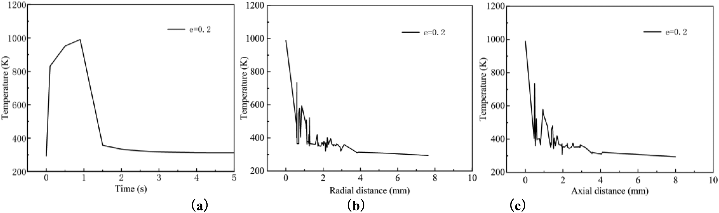
(a) Relationship between temperature and thermal shock time; (b) radial distribution trajectory of maximum temperature; and (c) maximum temperature axial distribution trajectory.
According to Figure 6(a), the highest temperature on CSG occurs at t = 1 s. During the thermal shock phase before t = 1 s, the temperature increases with the accumulation of thermal shock time. At the termination stage of thermal shock after t = 1 s, the temperature drops sharply, which is consistent with the results shown in the temperature distribution cloud maps at each time in Figure 5. Figure 6(b) and (c) shows the distribution trajectory of the highest temperature on the CSG surface along the radial and axial directions at t = 1 s. It shows that the highest temperature occurs at the tool tip, and the temperature gradient difference in the area 2.8 mm radially and 2 mm axially away from the tool tip approaches zero. The above results indicate that cutting temperature has a small effect on the surface tool material beyond 2.8 mm radially and 2 mm axially away from the tool tip.
Transient stress field
The temperature gradient difference formed during the thermal shock process causes internal expansion of the tool material, resulting in thermal stress. Figure 7 shows the distribution of the first principal stress of the CSG at each time step.

Distribution of the first principal stress at each time: (a) t = 0.5 s; (b) t = 1 s; (c) t = 2 s; and (d) t = 5s.
As shown in Figure 7, the first principal stress increases with the duration of thermal shock time. The first principal stress is 1.38 × 10⁸ Pa at t = 0.5 s and 1.43 × 10⁸ Pa at t = 1 s. After the thermal shock load is removed, the first principal stress still exists, which is 1.43 × 10⁷ Pa at t = 2 s and 9.13 × 10⁵ Pa at t = 5 s. The above phenomenon shows that the first principal stress on the CSG changes with thermal shock and cooling time, and the first principal stress is the largest when t = 1 s. However, the trace distribution of the stress field is not exactly the same as the gradient division of the temperature field, and it can also be seen from the stress distribution cloud map that there are low stress regions between adjacent high stress regions (in the stress distribution cloud map, the red region is the high stress region, and the blue region is the relatively low stress region).
Figure 8 shows the variation curve of the first principal stress with thermal shock time and the distribution trajectory of the first stress on the CSG. Figure 8(a) shows the variation of the first principal stress with thermal shock time. Before stopping the thermal shock, the thermal stress increases with the accumulation of thermal shock time, and the first principal stress on the tool surface reaches its maximum at 1 s. After stopping the thermal shock, the thermal stress decreases with cooling time. After 2 s, the first principal stress changes tend to stabilize but still exist, which is consistent with the results shown in Figure 7. At this time, the stress field is in a theoretically stable state. The above phenomenon shows that the distribution characteristics of the transient thermal stress field are different from that of the transient temperature field, but the maximum thermal stress values appear at t = 1 s, and the thermal and stress characteristics of the tool can be used to characterize the mechanical properties of the tool material. Figure 8(b) and (c) show the radial and axial distribution tracks of the first principal stress at t = 1 s, respectively. The maximum tensile stress appears at the position 0.632 mm in radial direction and 1.169 mm in axial direction away from the tool tip point, that is, the thermal stress value at the point (0.632, 1.169) is the largest, which has higher requirements for the seismic resistance of the tool material. In addition, Figure 8(b) and (c) also show that the stress gradient difference in the area 4 mm away from the axial and radial directions of the tool tip is almost zero. For the cutting tool with a cross-sectional size of 9.525 mm × 9.525 mm, this means that the cutting area near the tool tip is independent of each other. That is to say, during the entire thermal shock process, the cutting edges, and cutting areas corresponding to the eight tool tips on the CSG are independent and equally effective.

(a) The change of the first principal stress with the thermal shock time; (b) the radial distribution path of the first principal stress; and (c) the axial distribution path of the first principal stress.
Results and discussion
To investigate the impact of various structural parameters on the thermal stress field of CSG, including the number of gradient layers, step difference, and layer thickness ratio, a thermal stress distribution diagram was created at the location where the maximum tensile stress was observed (t = 1 s) under identical thermal shock conditions, as depicted in Figure 9.

(a) Relationship between layer thickness ratio and maximum tensile stress; (b) the relationship between the gradient difference and the first principal stress; (c) relationship between gradient layers and maximum tensile stress; and (d) the nephogram of the first principal stress position point for each gradient structure parameter.
As illustrated in Figure 9(a), when the layer thickness ratio is e = 0.1, the minimum tensile stress is 1.37 × 10⁸ Pa. This is followed by layer thickness ratios of e = 0.2 and e = 0.3, with the tensile stress increasing significantly at e = 0.4 (1.93 × 10⁸ Pa) and e = 0.5 (2.14 × 10⁸ Pa). These results indicate that the layer thickness ratio can regulate the stress value of CSG material, with smaller layer thickness ratios corresponding to lower maximum tensile stresses in CSG. Figure 9(b) shows that the stress values for gradient differences of 10%, 20%, and 30% exhibit minimal fluctuation(≈4 × 10⁵ Pa), suggesting that the gradient difference has a limited influence on stress. However, thicker surface material with a larger layer thickness ratio (e = 0.3) demonstrates superior wear resistance. Figure 9(c) reveals that the surface tensile stress decreases as the number of gradient layers increases. The maximum tensile stress of the surface layer in five-layer CSG decreases by 0.07 × 10⁸ Pa compared to that of the third layer (maximum tensile stress: 1.52 × 10⁸ Pa), while the maximum tensile stress of the surface layer in seven-layer CSG decreases by 0.03 × 10⁸ Pa compared to that of the fifth layer. This suggests that the ability of five-layer CSG to offset and transfer thermal stress is slightly inferior to that of seven-layer CSG, although five-layer CSG exhibits better workability.
Figure 9(d) shows the nephogram of the first principal stress position point for each gradient structure parameter. The labels x(a, b, c) in Figure 9(d) represent the structural parameters (thickness ratio, number of gradient layers, gradient difference) of the X CSG. For instance, 1 (0.1, 3, 30%) corresponds to the first CSG, where the layer thickness ratio is e = 0.1, the number of gradient layers is 3, and the gradient difference is 30%. The gray solid dot represents the projection of the corresponding red ball in the radial and axial planes. The closer the projection point is to the origin of the coordinate system, the closer the position of the maximum tensile stress is to the tip of the tool.
From Figure 9, it can be observed that the maximum tensile stress values are arranged in ascending order: 1(0.1, 3, 20%) < 2(0.3, 7, 30%) < 3(0.2, 3, 20%) < 4(0.3, 5, 30%) < 5(0.3, 3, 20%) / 6(0.3, 3, 10%) / 7(0.3, 3 30%) < 8(0.4, 3, 20%) < 9(0.5, 3, 20%). Among the nine types of gradient structural parameters, the position of the maximum tensile stress from far to near the tool tip is: 5 / 6 / 7 / 3 > 4 > 2 > 9 / 8 > 1. The results show that the maximum tensile stress of the fist CSG is the smallest, but it is closest to the tool tip; the position of the maximum tensile stress of the ninth CGS is the farthest from the tool tip, but the tensile stress value is the largest; the third and fourth class of CSG have good comprehensive properties. The other CSG have different degrees of approaching the tool tip area and large tensile stress, which is not suitable for the turning of ceramic tools with high efficiency and difficult to process materials.
In sum, the greater the distance between the maximum tensile stress of CSG and the tool tip position, the lower the stress value and the more improved the tool performance. Therefore, the optimized CSG materials are as follows: three-layer CSG with layer thickness ratio e = 0.2 and gradient difference of 30% (Figure 10(a)), and five-layer CSG with layer thickness ratio e = 0.3 and gradient difference of 30% (Figure 10 (a)).

CSG structure model: (a) three-layer and (b) five-layer.
In Figure 10 2g, d`, d, and 2b, w`, and w are the gradient dimensions of the first layer, the second layer and the surface layer, respectively. These dimensions are determined based on the layer thickness ratio formula.
Conclusion
Based on the theory of heat conduction, the heat flux density and boundary conditions, a theoretical model of heat conduction for CSG was constructed. The analytical formula for the thermal stress field was derived, and the transient thermal stress field was numerically simulated using the finite element method. The main conclusions are listed as follows:
Thermal conduction theoretical model and thermal stress analysis formula lay the theoretical foundation were constructed, promoting the thermal stress simulation of CSG. Before stopping the thermal shock, the temperature field and stress field on the tool accumulate with the thermal shock time. After the thermal shock stops, the tool surface temperature drops rapidly, the temperature field gradient difference approaches zero, and the residual thermal stress still exists, which is the root cause of the tool material failure. The eight cutting edges of the CSG are equally effective, the temperature field changes are consistent with the gradient distribution of the tool material, and the maximum thermal stress point on the tool is far away from the tip position, which eliminates or transfers the residual thermal stress caused by the temperature gradient difference. For additive manufacturing technology, two kinds of CGS with structural parameters of 3(0.2, 3, 20%) and 5(0.3, 3, 20%) were optimized by finite element method based on thermodynamic coupling mechanism.
In addition, the constructed theoretical model of CSG can be used for the optimization of thermal shock resistant gradient ceramic cutting tool material structure, providing theoretical references for the design and preparation of the other functional gradient materials.
Footnotes
Authors’ contributions
GZ was involved conceptualization, methodology, funding acquisition, writing original draft, and writing review & editing. GW was involved data curation and writing original draft. XH was involved writing review & editing, validation, data curation and supervision.
Funding
The authors disclosed receipt of the following financial support for the research, authorship, and/or publication of this article: This research was funded by the General Research Projects of Zhejiang Provincial Department of Education in China (Y202454556), in part by the Research Project of Jiaxing Nanhu University (62308YL), and the Science and Technology Plan Project of Jiaxing city in China (Grant. 2025CGZ049).
Declaration of conflicting interests
The authors declared no potential conflicts of interest with respect to the research, authorship, and/or publication of this article.