
Abstract
The present paper applies a length-scale insensitive degradation function to accelerate the simulation of thermal cracking problems. The solid deformation, damage evolution, and heat conduction process are coupled. The solid is treated as a linear elasticity, whose strain is composed of the mechanical strain and the thermal strain induced by thermal expansion. The cracks in solids are represented by the diffusive phase-field variables. The length-scale insensitive degradation function has been employed to decouple the length scale of the phase-field length scale and that of the physical process area, which alleviates the meshing burden of the phase field. The numerical results of our ceramic examples of interest are in good agreement with the experimental results, and this work may have important implications for predicting thermal cracking problems on large scales.
Introduction
The drastic temperature changes can induce thermal shock stress in solids. When the thermal stress value exceeds the strength of the solids, cracks will generate and propagate. 1 Many efforts have been made to simulate the thermal cracking phenomenon, for example, extended fine element methods 2 and remeshing strategies, 3 but these methods are cumbersome in simulating complex fracture networks. 4 In comparison, the phase-field method modeled the sharp cracks in a diffusive way. The phase-field method originated in the 1950s and was initially used to address mathematical modeling problems in phase transition processes such as solid-phase transformations and droplet coalescence. The Landau–Ginzburg theory was introduced to describe the phase field in continuous phase transition phenomena. Later, in 1969, Cahn and Hilliard first proposed the phase-field equation, which became an important foundation for phase-field method research. An additional field variable (phase-field variable) varying between 0 and 1 continuously is introduced to represent the cracks, with 0 meaning that the solid is intact and 1 indicating that the solid generates cracks. The advantage of the phase-field method is that it unifies the nucleation, propagation, branching, and coalescence of cracks.
Since its inception, phase-field method has been widely used in computational fracture mechanics, including brittle fracture, dynamic fracture,5–7 ductile fracture, 8 hydraulic fracture,9–11 fracture in piezoelectric ceramics, 12 and composite electrode. 31 The phase-field fracture model 32 seeks the displacement field and crack set by minimizing the total potential energy of the cracked solid, in order to extend Griffith's theory. Some scholars conducted thermal shock experiments on rectangular ceramic plates using the phase-field cohesive zone model, 13 others have implemented a parallel algorithm for the thermoelastic coupled phase-field model and applied it to simulate dynamic brittle fracture and quasistatic brittle fracture of thermoelastic materials. 14 Thermodynamically consistent phase-field model for thermal fracture is proposed. 15
Nonetheless, within the phase-field method, the region surrounding a fracture is intricately connected to a minor physical length scale. This scale is associated with the fracture energy and the strength of the material. Achieving precise outcomes necessitates the utilization of an exceedingly fine mesh to accurately capture this length scale. The huge mesh density reduces the efficiency of phase-field method. In order to improve the computational efficiency of the phase-field method, many scholars both domestically and internationally have made significant efforts. For instance, Zhang et al. 34 demonstrated the effectiveness of certain acceleration techniques in dealing with dual-crack systems. Reduced-dimensional models 35 are also an option, which simplifies the problem by reducing the degrees of freedom. Additionally, adaptive mesh refinement methods, such as the one proposed by Goswami et al., 36 can dynamically adjust the mesh density based on the solution characteristics to balance the computational accuracy and efficiency. Yin et al. 33 propose a novel phase-field fracture method to make the relation between the diffusive length scale and the material parameters adjustable via modifying the energetic degradation functions. Furthermore, some researchers proposed a length-scale insensitive degradation function for phase-field models, and it is widely used to solve the fracture problem of large linear elastic structures. 16 The novel degradation functions decouple the physical length scale and the phase-field length scale, thus allowing for a phase-field length scale much larger than the physical process zone length scale.
The present paper is intended to apply the length-scale insensitive degradation function to accelerate the simulation of thermal cracking problems, and it is an initial validation of the potential ability of the method for solving large-scale thermal cracking models. The quenching tests of the ceramic plate are considered to validate the feasibility and numerical implementation. The simulated crack morphology and response are compared with the experimental results.
The remainder of the paper is organized as follows. The accelerated phase-field models for thermal cracking are introduced in “Theoretical equation” section. “Finite element discretization” section is the finite element implementation of the governing equations. “Algorithmic examples” section shows some typical examples of thermal shocks involving brittle fracture failure, followed by “Conclusion” section.
Theoretical equation
The theoretical aspect of the thermal fracture phase-field method is discussed, focusing on achieving constant peak stress by modifying the degradation function, regardless of the length scale of the physical process zone surrounding the fracture.
Displacement and damage equations
The solid crack region is represented by
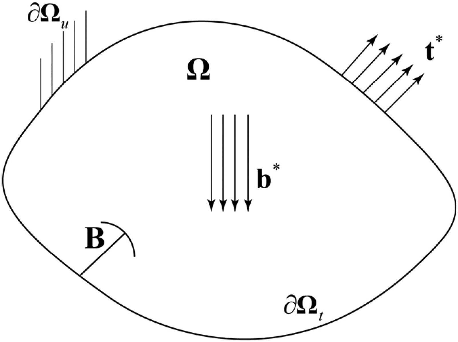
A cracking solid.
In the phase-field method,
17
sharp fracture
Governing equations
The mechanical control equation and the damage control equation can be written as
21
:


Constitutive relations
The constitutive equations that define the stress


Thermal equations
In this section, we introduced the heat conduction process in the solid.
21
The external boundary is divided into two parts, one is given the temperature
Governing equations for the heat transfer process
The following equation describes the heat conduction process in the solid,


Constitutive relations
The strain in solids consists of two parts one is mechanical strain


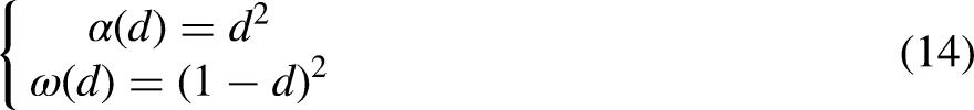
The length-scale insensitive degradation function
The phase-field formulation for thermal cracking has already been provided. In traditional phase-field modeling, the geometric crack functions and energetic degradation functions typically assume the following forms:

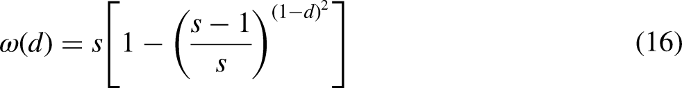
Regarding the graphical representation of this energy degradation function and the decoupling of phase-field length scale and physical length scale through parameter s, interested readers can refer to Yang et al. 25
Employing this degradation function enables us to redefine the expression for the peak stress in a bar subjected to homogeneous uniaxial tension as follows:


Finite element discretization
This section presents the finite element implementation of the model using the multifield elements. Here, multifield elements consist of displacement degrees of freedom, damage freedom, and temperature degrees of freedom. “Weak form” section describes the weak formal expression of the multifield element under study, and “Finite element discretization” section is the finite element discrete part.
Weak form
Next, we need to rewrite the above control equations into the following weak form:


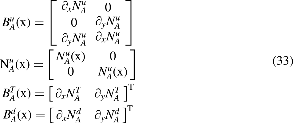
Finite element discretization
The displacement field


Algorithmic examples
This section primarily presents a pair of representative cases to illustrate the efficacy of the length-scale insensitive degradation function within the phase-field approach to thermal cracking. Plane stress conditions are applied consistently throughout the subsequent examples. The intact material is denoted by the blue region, whereas the red region signifies the presence of cracks. The numerical cases mentioned before employ a staggered procedure to address the nonlinear coupled equations.
Quenching experiment of rectangular ceramic plate
The quenching experiment of rectangular ceramic plates
26
is considered, where a rectangular ceramic plate measuring 50 mm in length and 10 mm in width is initially heated to
Parameters of quenching experiment of rectangular and circular ceramic plates.

Figure 2(a) shows the final crack distribution in the ceramic plate quenching experiment. It can be seen that after the thermal shock, the cracks on the surface of the rectangular ceramic plate are almost perpendicular to the edges. Since the specimen is uniform, the cracks exhibit an axisymmetric pattern.

The quenching experiment of rectangular ceramic plate: (a) The experimentally observed crack pattern; (b) The numerical model depicting the geometry and applied boundary conditions; (c) The finite element mesh diagram in COMSOL.
In the numerical simulation experiment, the thickness of the rectangular plate is set to 1 mm, the initial temperature is 300°C, and the ambient temperature is 20°C. Figure 2(b) shows the two-dimensional numerical simulation model of the ceramic plate. During the initial grid division, a uniform grid is used based on the geometric shape and dimensions of the model, as shown in Figure 2(c). The minimum grid size is set to 0.05 mm, and the complete grid contains 50,000 domain elements and 1200 boundary elements.

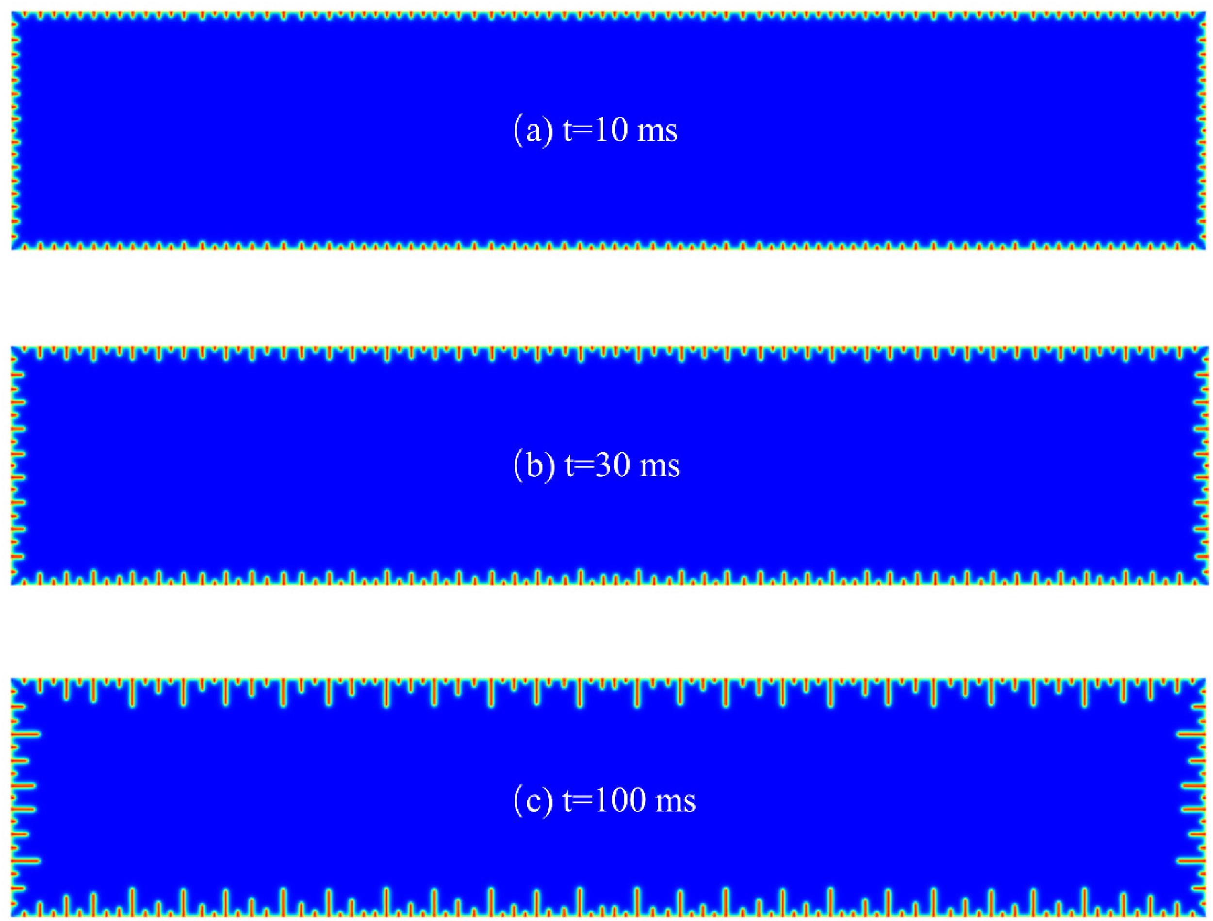
Classical AT2 degradation functions applied to thermal shock, numerical observation of cracking patterns.
The smallest grid size has a significant impact on the simulation results, and it can even directly affect whether the results converge. In this work, the minimum grid scale is set to 0.05, which is a value we determined through experimentation during the numerical simulation process, ensuring convergence across different phase-field characteristic scales. If this minimum grid scale is further increased, the final computational results will not converge under certain phase-field scales, meaning the crack propagation predictions cannot be obtained. On the other hand, reducing the grid size further will lead to an increase in computational time as the number of computational domains grows.
In addition, the initial rectangular plate is intact, so d = 0 acts on all boundaries. The length scale 
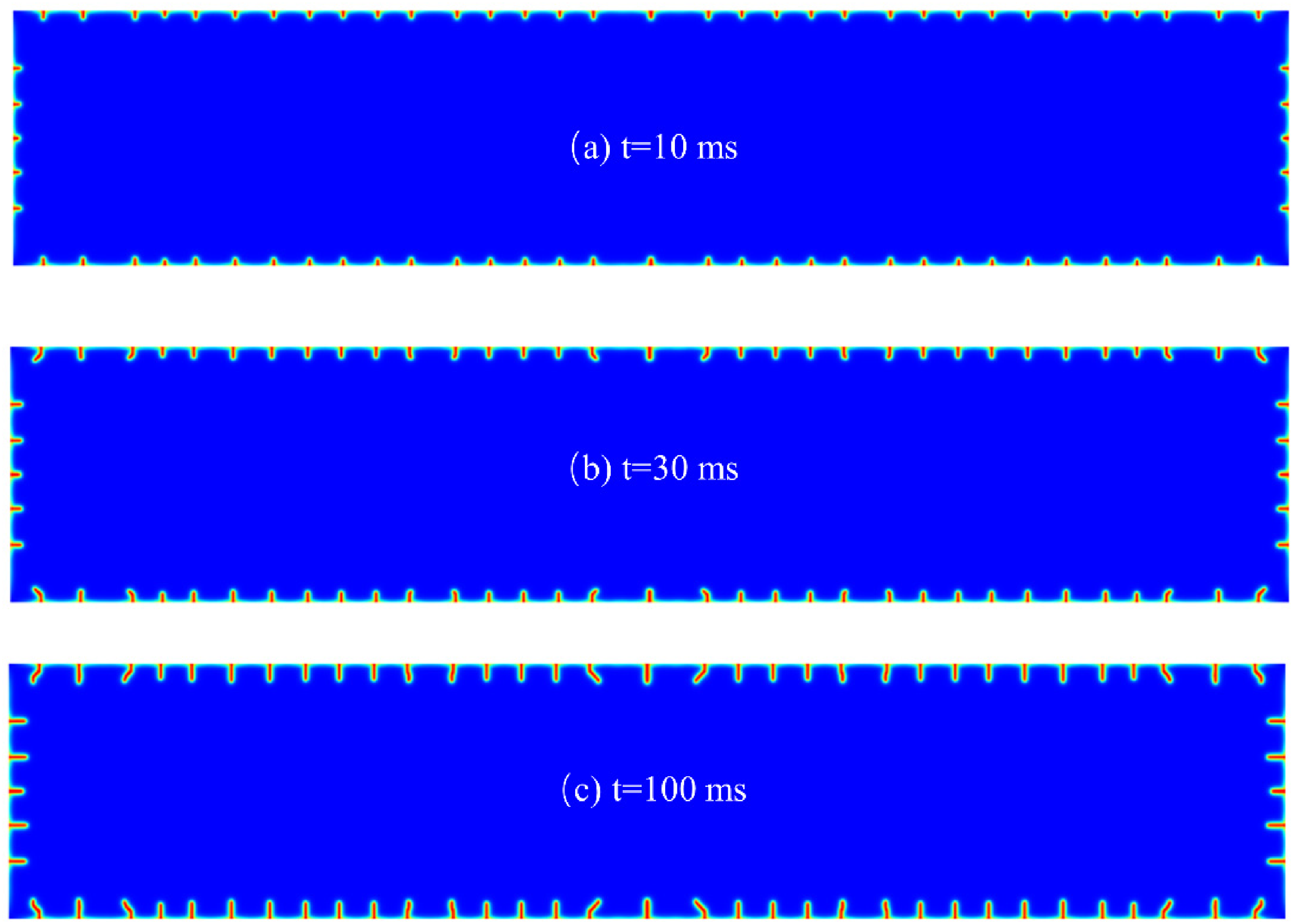
Subsequently, we incorporate the degradation function that is unaffected by the length scale into our model. The length scale

s = 200,

s = 5,
s = 1.1,
s = 1.04,
The crack distribution at t = 100 ms is taken as the final crack morphology simulation result. Cracks with lengths exceeding 0.25 mm are considered valid cracks. The distribution of the number of valid cracks under the above parameter settings is shown in the following (Figure 8). The orange and green bar charts represent the number of valid cracks on the long and short edges of the rectangular ceramic, respectively.

Comparison of the thermal crack number obtained from the present numerical tests and the previous experimental observations. 26
It can be seen that when AT2 and s = 200, the numerical simulation results are closest to the experimental results. Except for these two cases, the number of valid cracks is the closest to the experimental results when s = 1.1. In terms of computation time, the smaller the s value, the less time is consumed in the calculation. In this case, when s = 200, the computation time is 24,194 s, whereas when s = 1.1, it only takes 16,975 s, resulting in a 29.8% improvement in computational efficiency. Therefore, considering both computational efficiency and time, using s = 1.1 is more optimal in this case. In addition, during the experiment, shorter cracks may nucleate at the edge of the plate, and the simulation captures some key features: a series of periodic parallel short cracks nucleate, followed by selective arrest and growth.
It is evident from Figure 9 that quenching process induces a significant temperature gradient in the outer layer while maintaining little temperature variance internally. The propagation of cracks exhibits notable stability, with their tips evolving along with the edges of the central high-temperature region, serving to alleviate stress around the crack tip. Numerical simulations demonstrate the relevance of this degradation process in the thermal fracturing of ceramic plates. The closely resemblance between crack networks generated through stochastic simulations and real crack formations aids in a deeper comprehension of crack development resulting from thermal shock.
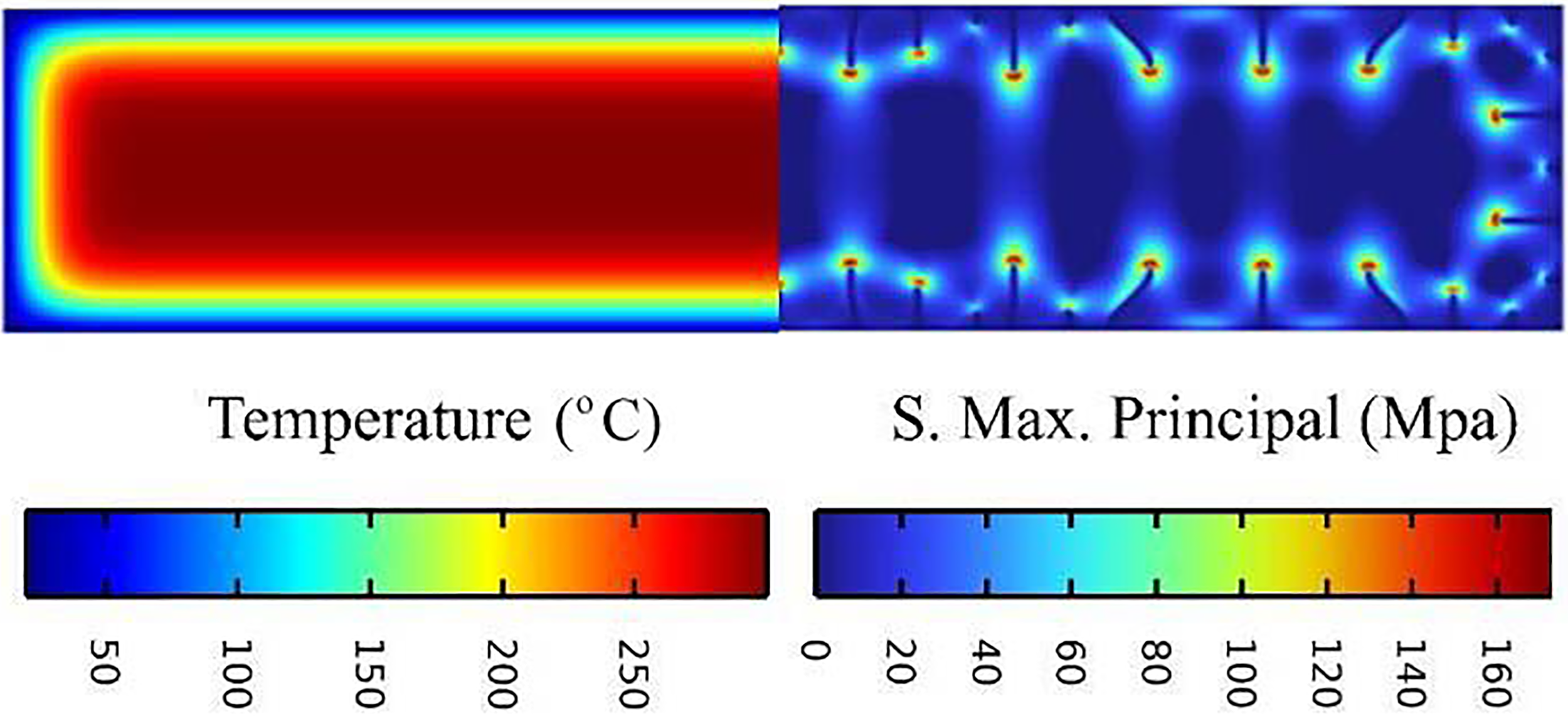
Temperature and maximum principal stress plots of rectangular ceramic plates at t = 0.1 s.
2-D thin circular ceramic specimen in quenching tests
The quenching test of 2-D thin circular ceramic plates
30
is considered; 99%
From the experiment result shown in Figure 10, it can be seen that after the specimen is subjected to thermal shock, the crack formed by thermal shock is perpendicular to the circular edge and points to the center. At the same time, we can also observe that the crack pattern on both sides of the specimen is the same, indicating that the crack pattern presented is axisymmetric, which we can easily observe. This issue has been studied in the literature. 29 Material parameters are shown in Table 1. Figures 11–15 show the simulation results of applying different degradation functions acting on circular ceramic plates for thermal shock experiments.

Thermal shock crack patterns, where the preset temperature

Classical AT2 degradation function applied to circular ceramic plates, numerically observed crack pattern.

s = 200,

s = 5,

s = 1.1,

s = 1.04,
Figures 11–15 illustrate various stages of the fracture process. Observing these images allows for a summarized understanding of the pattern of crack propagation. Initially, thermal shock initiates cracks that propagate uniformly with nearly equal spacing (Figures 11–15(a)). At this stage, crack propagation is rapid, gradually decelerating as thermal stress dissipates, until the number of cracks exceeds the range supported by strain energy. Consequently, only a few cracks continue expanding while others cease propagation, and the distance between cracks increases (Figures 11–15(b)). Subsequently, crack propagation may deviate, attempting to establish equidistant spacing. This process may repeat multiple times until the strain induced by thermal stress can no longer support the expansion of any further cracks. Ultimately, the simulated crack patterns closely resemble the observed patterns (Figures 11–15(c)).
It can be seen from Figure 16 that when the temperature gradient reaches a certain level, cracks initiate from the position of maximum principal stress. Subsequently, stress relaxes at that point, leading to stress redistribution and changes in the location of maximum principal stress, facilitating continual crack initiation. The propagation of cracks arrest when the temperature gradient no longer induces sufficient stress concentration. During thermal shock, stress is uniformly distributed on the specimen's surface, resulting in a certain degree of randomness in the location of maximum principal stress.

Temperature and maximum principal stress plots of rectangular ceramic plates at t = 0.1 s.
The data in Table 1 are all from.23,26,28 This work assumes that the material parameters remain constant despite temperature changes. The initial temperatures chosen for analysis are
By decreasing the value of s, the phase-field length scale
Conclusions
The study effectively integrates a degradation function that is insensitive to the length scale into the phase-field method for modeling thermal cracking. Moreover, the displacement equations, damage equations, and the heat conduction process in the solid are introduced. The research introduces a degradation function that effectively disentangles the physical dimensions from the phase-field dimensions in the context of thermal cracking, leading to a reduced necessity for mesh density to resolve the diffusive zone. To a certain extent, it breaks through the limitation of the original small scale. Through some numerical examples that we are particularly interested in, the crack evolution, nucleation, propagation, and arrest behaviors of cracks are well captured, the applicability of the length-scale insensitive degradation function to the phase-field method of thermal cracking is verified, which opens the door for the extension of phase-field fracture theory to the simulation of large engineering structures and also has a particular guiding role for the fracture simulation of other multiphysical field problems.
In addition, the degree of decoupling between the phase-field length scale and the physical length scale of the material is limited, and further implementation of engineering simulations at larger scales needs to be further investigated. Like brittle fracture, the phase-field method also holds great potential in the field of ductile fracture. In the future, we will also explore the application of length-scale-insensitive degradation functions to ductile fracture models to expand the range of the model's application.
Footnotes
Author contributions
Lusheng Yang: Methodology, software, validation, formal analysis, investigation, and writing—original draft. Gengyin Yang, Yujing Ma, and Hongyu Li: Writing and methodology. Zhuxuan Meng, Xuan Peng, and Zhenghe Liu: Conceptualization, methodology, writing, supervision, and acquisition of the financial support.
Data availability statement
The data that support the findings of this study are available from the corresponding author upon reasonable request.
Declaration of conflicting interests
The author(s) declared no potential conflicts of interest with respect to the research, authorship, and/or publication of this article.
Funding
The author(s) disclosed receipt of the following financial support for the research, authorship, and/or publication of this article: This research was funded by National Natural Science Foundation of China, grant number (grant numbers 52274222, 52174123).