
Abstract
Analytical and numerical methods are often used to study the behavior of multiphase fluid under electric field. Compared with analytical methods, numerical methods can simulate the real physical phenomenon of multiphase fluid dynamics in a large deformation range. The finite element method is mainly applied in two-phase fluid currently, although it can be used to analyze the small and large deformation of multiphase fluid under electric field. This article attempts to develop a finite element model of a concentric compound drop immersed in continuous medium under electric field based on the ternary phase field method and simulate the electrohydrodynamics of the compound drop whose core phase, shell phase, and continuous phase are different. The small deformation simulation results of the compound drop under weak electric field are compared with the analytical results of previous researchers from the three aspects, namely, deformation, free charge distribution, and flow pattern. This model is proved to be effective under certain conditions. Based on this premise, the large deformation and breakup of the compound drop under high electric field are further simulated to investigate the mechanism of compound drop breakup preliminarily.
Keywords
Introduction
The study of drop behavior in electric field plays an important role for the primary theory of electrohydrodynamics (EHD). In recent years, the application of EHD in industrial production such as electrostatic spraying, electrostatic spinning, ink jet printing, oil–water separation, and electrowetting is increasing, which urgently needs the theoretical research to predict and optimize the fluid behavior in electric field. The simplest way is to study the deformation of drop under two parallel electrode plates. Based on the well-known leaky dielectric model of Taylor, 1 the steady-state EHD of a single drop in weak electric field has been well understood. However, a numerical method has to be used to study the drop behavior in high electric field because the drop fails to reach a balance.
Many numerical methods are used to simulate the EHD of single droplet, such as boundary integral method (BIM), volume of fluid (VOF), level set (LS), and lattice Boltzmann method (LBM). Sherwood 2 studied the large deformation and breakup of single droplet subjected to electric field using BIM and found that pointed ends were predicted when the permittivity of droplet was greater than that of the surrounding fluid; however, the droplet experienced division into blobs when the conductivity of the droplet was higher compared with that of the surrounding fluid. Paknemat et al. 3 using the LS method with the ghost fluid method investigated the deformations and breakup modes of three types of droplets in an electric field, and the simulation results were compared with similar numerical and experimental results. The VOF method was utilized by Tomar et al. 4 to predict the droplet deformation in an electric field and the electrocoalescence behavior of two droplets. Using the coupled level set and volume of fluid (CLSVOF) method, Huang et al. 5 simulated the breakup behavior of the leaky dielectric droplet under direct current electric field. They found that the evolutions of velocity field and pressure field determined the breakup mode transformation. Lin et al. 6 used the phase field method to simulate the deformation of a single droplet for leaky and perfect dielectric fluids in an electric field, and the results were found to be in good agreement with the existing theoretical and numerical studies. Based on the three different electric field models, namely, leaky dielectric model, perfect dielectric model, and constant surface charge model, Hua et al. 7 used the front tracking method (FTM) to simulate the deformation of single droplet suspended in viscous liquids subjected to an external electric field, and the reasonable prediction was obtained. Singh et al. 8 presented a low spurious current lattice Boltzmann model and simulated the interaction of single or multiple droplets suspended in the outer fluid in the presence of an electric field by employing this model. By coupling multi-component LBM with the leaky dielectric model, they also conducted a numerical study of deformation and breakup of a droplet subjected to shear flow under an electric field. 9 The numerical studies of drop EHD outlined earlier concentrate on leaky dielectrics, perfect dielectrics, or perfect conductors. The electrical properties are considered to be uniform within each fluid phase in these cases. However, for electrolyte solutions with mobile charge carriers, gradients of ion concentration form in an electric field, causing non-uniform conductance and thereby affecting the operation of microfluidic devices significantly. Therefore, there is a need for a multiphase electrokinetic flow model that is capable of tracking single and multiple species of mobile charge carriers. Based on the CLSVOF technique, Berry et al. 10 and Pillai et al. 11 developed the first numerical method to incorporate ion transport into a model of electrokinetic two-fluid flow and investigated the deformation and breakup of an electrolyte drop under the action of an electric field. Davidson et al. 12 extended their model to allow for interfacial charge and simulated the deformation of a hexadecane drop in pressure-driven electrokinetic flow of electrolyte solution through a microchannel by employing this extended model along with a modified pressure formulation.
Compound drop is a fluid particle consisted of an inner drop encapsulated by another immiscible fluid which is itself immersed in a third fluid. It is encountered in a variety of technologically significant processes. Examples of these processes include liquid membranes for selective mass transport, water purification, controlled release of drugs, direct contact heat exchange, and recovery of heavy metals.13,14 Application of electric field can improve the efficiency of the processes involving compound drops. Hence, the study on the behavior of the compound drop under the influence of electric field is of particular importance to deeply comprehend these processes and provide guidance to practical applications. But compared with single-phase drop, EHD of the compound drop is quite less explored. From the standpoint of experiment, the density of three fluids must be close in order to stabilize the compound drop because of buoyancy caused by the difference in density, which greatly limits the variety of fluid studied. It is only known that Tsukada et al. 15 performed a deformation experiment of a kind of special compound drop whose core phase and continuous phase are the same in a uniform electric field. Thus, analytical and finite element methods are often used. Ha and Yang 16 investigated the influence of uniform electric field on the fluid dynamics of a concentric compound drop analytically and successfully characterized the flow patterns by obtaining the approximate solutions of electric and velocity fields and examining the charge distribution at the inner and outer interfaces. They found that the second recirculating flow occurred in the shell phase when the charges at the core–shell and shell–continuous medium interfaces are the same property. Based on the leaky dielectric theory, Behjatian and Esmaeeli13,14 studied the behavior of a concentric compound drop in a uniform electric field and analyzed the electric field and flow pattern in detail by the analytical method. The results showed that there were four possible flow patterns in the compound drop, and the dielectric constant and conductivity of fluid played a crucial role in determining the steady-state evolution of flow field. However, since the studies of Ha and Yang 16 and Behjatian and Esmaeeli13,14 are based on the domain perturbation procedure, they can only accurately predict small deformation of the compound drop in an electric field. Compared with analytical studies, numerical studies can simulate the real physical phenomenon of compound drop dynamics in large deformation range and predict the compound drop breakup accurately. Several numerical studies on a compound drop in electric field have been conducted so far. Soni et al. 17 used the phase field method to simulate the dynamics of the compound drop in a uniform electric field. The results showed that the simulation results were in good agreement with the experiment results of Tsukada et al. 15 However, since the core phase of the compound drop studied was the same as the continuous phase, the phase field method employed was still a two-phase flow method. Abbasi et al. 18 used the LS method to simulate the instability behavior of the compound drop under high electric field. The results suggested that when the core drop was eccentric, the electric field would induce it to be concentric with the shell drop or be close to the shell–continuous phase interface depending on electrical parameters. But the compound drop studied was still a two-phase fluid system in which the core phase was the same as the continuous phase. Moreover, the LS method cannot be extended to three-phase flow. In other words, the phase field and LS methods employed in the aforementioned two studies cannot be employed to simulate the EHD of the compound drop whose core phase, shell phase, and continuous phase are different. To our knowledge, the EHD of the compound drop whose core phase, shell phase, and continuous phase are different has not yet been studied by numerical simulation.
This work mainly includes four parts. First, a theoretical model is proposed for the coupling of electric field and three-phase flow field. Second, a finite element model of a concentric compound drop immersed in continuous medium under electric field is developed based on the ternary phase field method. Then, its feasibility and applicable range are confirmed by comparing the simulation results of small deformation of the compound drop with the analytical results of previous researchers in three aspects, namely, deformation, charge distribution, and flow pattern. Finally, the large deformation and breakup of the compound drop under high electric field are simulated under different electrical parameters to explore the mechanism of compound drop breakup preliminarily.
Theory
Ternary phase field theory
The ternary phase field model proposed by Boyer et al. 19 is used to track the interfaces among three immiscible fluids. This model is solved based on the following Cahn–Hilliard equations


where

where
The parameter


where
F is defined as a function of phase field variable
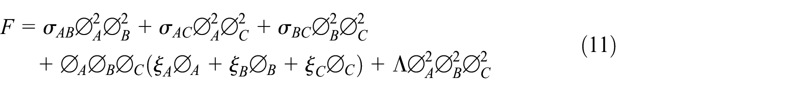
where
Electric field theory
For leaky dielectric fluids, both free and polarized charges should be considered. So, it can be started with Gauss law


where
The electric field can be assumed to be irrotational

Free charge density

where
If each fluid phase satisfies

If Case a cannot be satisfied, the electric field governing equation is the general form of equation (15) and given as follows

Equation (17) becomes the following form by combining equation (14)

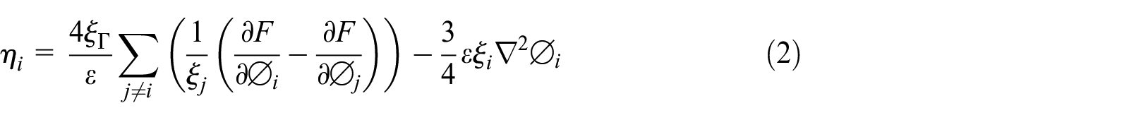
Finally, for simplicity, the functions in parentheses of equation (16) and square brackets of equation (18) are referred to as


where
The coupling
Drop deformation generates when electric stress overcomes surface tension and viscous stress. It is assumed that the fluid is incompressible and the viscosity is irrotational. So, the governing equations are as follows


where p and I are the pressure and unit matrix, respectively,
According to the ternary phase field method, the surface tension force

The electric stress per unit volume


Review of analytical research on a compound drop in electric field
The key factors for EHD of a compound drop are the conductivity ratio
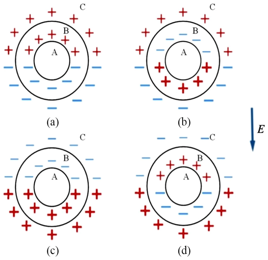
Charge distribution of compound drop: (a)
The weak electric field can induce a circulation flow in the compound drop, and the flow pattern also has an important relationship with the electrical properties of fluids. According to the research work of Ha and Yang 16 and Behjatian and Esmaeeli, 13 flow patterns are mainly divided into four cases, as shown in Figure 2. The charge distributions in Figure 1(b) and (d) lead to the flow patterns of Cases a and b in Figure 2, respectively. However, when the charge property at the core–shell interface is the same as that at the shell–continuous medium interface, the flow pattern depends on the magnitude of electric stresses at these two interfaces. If the electric stresses are comparable, the charge distributions in Figure 1(a) and (c) result in the flow patterns of Cases c and d in Figure 2, respectively. If the difference in electric stresses at these two interfaces is much, the flow patterns of Cases a and b in Figure 2 may result from the charge distributions in Figure 1(a) and (c), respectively.

Flow patterns of steady-state electrohydrodynamics of compound drop: (a) Case a, (b) Case b, (c) Case c, and (d) Case d.
Methodology
Numerical method and geometry
COMSOL Multi-physics 5.3 which is a commercial package based on the finite element method is used to simulate the EHD of compound drop. Since weak form is an integral form and has a low requirement for the continuity of field variable, it is very suitable for nonlinear multi-physics problems. Thus, the Navier–Stokes equations (equations (21) and (22)) and the governing equations of the ternary phase field (equations (1)–(10)) are first transformed into weak form and then solved.
It is assumed that a concentric compound drop is immersed in the infinite continuous medium. Thus, more solution efficiency can be applied to the interest domain as small as possible. As shown in Figure 3, the cylindrical coordinate is used. The compound drop consists of core drop with a radius of

Computational domain and boundary condition.
As shown in Figure 4, the uniform triangular element is used in meshing most regions, and the grids are encrypted at the initial interface of the compound drop with a scaling of 0.5. This mesh is applied in all the simulations. The adaptive mesh refinement is performed in order to simulate the EHD of the compound drop more accurately. The quadratic and linearity are used in the discretization of electric field governing equations and flow field governing equations, respectively, so as to ensure the solution accuracy and improve the convergence.

Mesh used in simulations.
Parameter set
The two key parameters in the ternary phase field method, namely interface thickness

Due to the fact that

Simulation conditions
Six leaky dielectric systems from the study by Behjatian and Esmaeeli 13 are used in the small deformation simulations of the compound drop under weak electric field. The key physical properties of six leaky dielectric systems are extracted from Behjatian and Esmaeeli 13 and given in Table 1.
Properties of leaky dielectric systems extracted from the study of Behjatian and Esmaeeli. 13

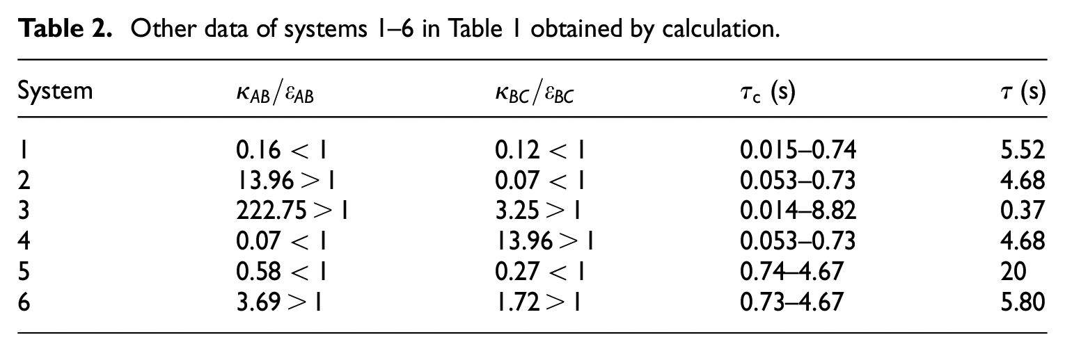
For comparison, the definition of time scale of flow

where
Other data of systems 1–6 in Table 1 obtained by calculation.
The small deformation simulation results are compared with the analytical results of Behjatian and Esmaeeli13,14 in terms of deformation, free charge distribution, and flow pattern to evaluate the feasibility and applicable range of the proposed model. After that, the large deformation and breakup of the compound drop are simulated under high electric field to show the topological advantage of the proposed model. In these simulations, the magnitude of conductivity and relative dielectric constant of three fluids is about 10−3 S/m and 10, respectively. Thus, the charge relaxation time
Results and discussion
Small deformation of the compound drop under weak electric field
Under small deformation condition, a dimensionless parameter D is usually used to assess the drop deformation. It is defined as

where b and a are the length of drop axis parallel and perpendicular to the electric field, respectively. Due to the presence of core and shell for the compound drop, core drop deformation and shell drop deformation are defined as
Figure 5 shows the variation in core drop deformation

Comparison of core drop deformation
Figure 6 shows the distribution of free charge and electric stress for systems 1–6. It can be found that the distribution of positive and negative charges for systems 1–6 is in accord with the analytical results of Behjatian and Esmaeeli.
13
As can be seen in Figure 6, except system 3, the charges for the other five systems distribute very closely to the interfaces. The free charges in system 3 (Figure 6(c)) enter into the shell phase, which results in the relatively large deviation in the deformation of the compound drop from the analytical results of Behjatian and Esmaeeli (Figure 5(c)). It can be seen from Table 1 that the conductivity ratio of the core phase to the shell phase for system 3
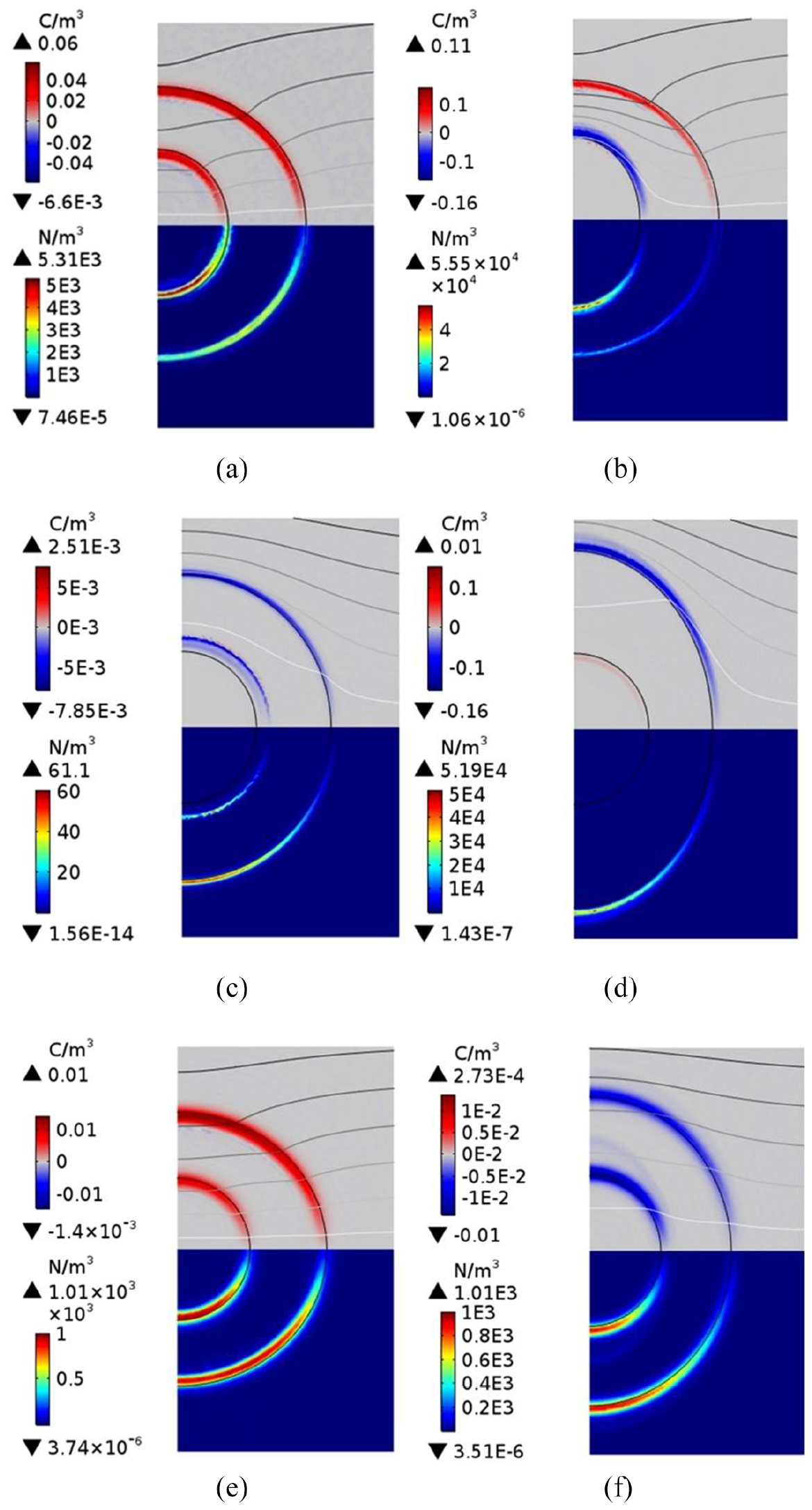
The distribution of free charge and electric stress for systems 1–6: (a) system 1, (b) system 2, (c) system 3, (d) system 4, (e) system 5, and (f) system 6.
By observing Figures 5 and 6, it can be found that although the charge distribution for system 1 is similar to that for system 5, the tendency of deformation of the compound drop is different. The same phenomenon also exists in systems 3 and 6. Thus, it is necessary to further examine the flow pattern. Figure 7 shows the flow patterns of systems 1–6. It can be found that the flow patterns of systems 2, 4, 5, and 6 are exactly consistent with the analytical results of Behjatian and Esmaeeli, 13 but there is a deviation for those of systems 1 and 3. The flow direction obtained by Behjatian and Esmaeeli 13 is marked using red rotating arrow in systems 1 and 3 (Figure 7(a) and (c)). The abnormal distribution of free charge (Figure 6(c)) causes a deviation in the flow pattern of system 3. However, the deviation in the flow pattern of system 1 surprised us. In the research work of Behjatian and Esmaeeli, 13 the flow pattern of system 1 is Case a in Figure 2, which generates when the difference in electric stresses at the core–shell and shell–continuous medium interfaces is very big. But in our simulation, there is not much difference in the electric stresses at these two interfaces (Figure 6(a)), consequently bringing about a deviation of flow pattern of system 1. As can be seen in Figure 7(a), there is a large velocity in the core drop close to the symmetry axis, which is roughly equal to the velocity at the shell–continuous medium interface. This velocity drops by two orders of magnitude at the core–shell interface. It is believed that the flow field outside the core–shell interface is not sufficient to overcome the internal flow field of core drop and change the flow direction in core drop. The secondary flow circulation is infinitely small at the core–shell interface, making the flow at the interface relatively stationary (Figure 7(a)). Therefore, this phenomenon can be understood as the transition from Case c to Case a in Figure 2.

Velocity stream lines and direction arrows for systems 1–6: (a) system 1, (b) system 2, (c) system 3, (d) system 4, (e) system 5, and (f) system 6.
In conclusion, the conductivity ratio of two adjacent fluids for the compound drop is found to be the only parameter that significantly restricts the accuracy of the proposed model. Figure 8 shows the relationship between conductivity ratio of two adjacent fluids

The relationship between
Conductivity ratio of leaky dielectric fluids used in different ITMs.

ITM: interface tracking method; FTM: front tracking method; GFM: ghost fluid method; LS: level set method; PF: phase field method; VOF: volume of fluid method.
The best agreement range compared to the analytical results.
Large deformation and breakup of the compound drop under high electric field
Figure 9 shows the variation in core–shell and shell–continuous medium interfaces of the compound drop with different electrical parameters under high electric field. When the ratio of
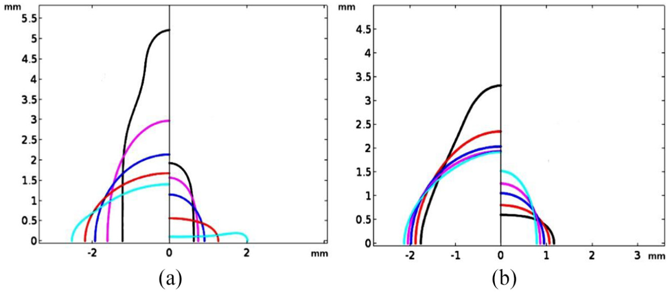
Variation in core–shell and shell–continuous medium interfaces of compound drop with electrical parameters under high electric field. (a) The color black, magenta, blue, red, cyan correspond to
Figure 10 shows the breakup processes of compound drops for different electrical parameters. As shown in Figure 10, the breakup first occurs in the core drops and near the symmetry axis. Figure 11 shows the distribution of electric field, charge, velocity, and pressure when compound drops nearly break up. As can be seen in Figure 11(a), under the action of electric field, the core–shell and shell–continuous medium interfaces are driven toward the opposite directions due to the positive charges at the shell–continuous medium interface and the negative charges at the core–shell interface. When the two interfaces contact, part of positive and negative charges cancel each other, leading to a sharp decline in electrical force. The charges concentrate near the largest curvature of the core–shell interface (Figure 11(a)), thus forcing the core drop to break up into two drops. One attaches to the shell–continuous medium interface (Figure 10(a)) due to the fact that the charges are neutralized and then electric force cannot overcome the viscous force, the other reaches a balance under the action of electric force and surface tension (Figure 10(a)). As shown in Figure 11(b), since the charges at the core–shell interface are much more than those at the shell–continuous medium interface, the movement of compound drop is almost determined by the core–shell interface. This means that the breakup of shell–continuous medium interface may be driven by the core–shell interface, and consequently a new compound drop forms.
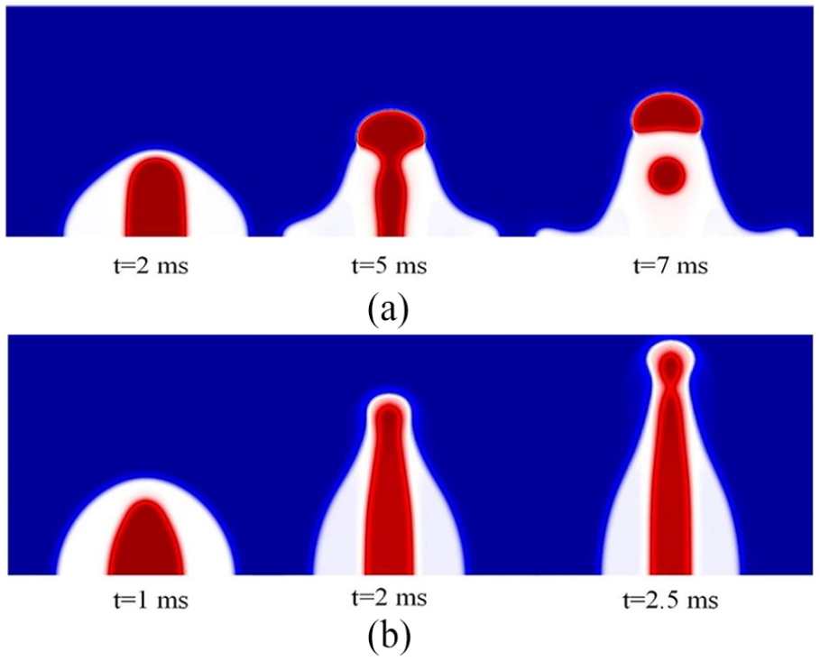
The breakup of compound drop for different electrical parameters under high electric field (E0 = 3 MV/m,

The distribution of electric field, charge, velocity and pressure for the forthcoming breakup of compound drop in Figure 10. (E0 = 3 MV/m,
Conclusion
Based on the ternary phase field method, a finite element model is developed to simulate the EHD of the compound drop whose core phase, shell phase, and continuous phase are different in this article. The simulation results of small deformation of the compound drop under weak electric field show that the proposed model may have a good accuracy when the conductivity ratio of two adjacent fluids
Footnotes
Appendix 1
Declaration of conflicting interests
The author(s) declared no potential conflicts of interest with respect to the research, authorship, and/or publication of this article.
Funding
The author(s) disclosed receipt of the following financial support for the research, authorship, and/or publication of this article: The authors wish to acknowledge with financial support of this research by China Postdoctoral Science Foundation (2017M610303), National Natural Science Foundation of China under contract no. 51205177, Natural Science Foundation of Jiangsu Province under contract nos. BK2012277 and BK20171307, Natural Science Program for Basic Research of Jiangsu Province under contract no. 08KJB460002, and Research Fund of DML-HYIT (HGDML-0901).