
Abstract
As the critical components in hydrogen refueling, storage, and transportation systems, the degradation and failure of rubber O-ring seals under a high-pressure (HP) hydrogen environment (up to 100 MPa) directly affect hydrogen energy safety. Clarifying the interaction mechanism of hydrogen diffusion and the mechanical properties of rubber seals is essential for HP hydrogen infrastructure. A hydrogen diffusion-mechanical sequential numerical model is built to investigate the sealing performance and hydrogen diffusion behaviors of rubber seals using ABAQUS software. The effects of hydrogen swelling environmental pressure (5∼100 MPa) and stress-concentration gradient on mechanical and contact characteristics and hydrogen concentration distribution are analyzed for the rubber seals with/without backup rings, respectively. Furthermore, the orthogonal experimental and comprehensive frequency analysis methods are employed to evaluate the significance of the main structural and assembly parameters and obtain the optimal schemes of the rubber seals under the HP environment. The results show that the stress concentration and rubber extrusion easily occur at the sealing clearance of the O-rings with swelling after pre-compression and pressurization. The hydrogen diffusion of the O-ring is mainly driven by the concentration difference and stress gradient, with the former being the dominant factor. With the increase in the hydrogen pressure, the effective sealing rate along the sealing surface decreases sharply, and the non-uniformity of hydrogen concentration and the possibility of fatigue damage in the rubber O-rings increase. Two multi-objective optimization schemes (Ⅰ and Ⅱ) for the main structural and assembly parameters of rubber seals are obtained by intuitive analysis and comprehensive frequency analysis to improve the extrusion tendency and sealing reliability of rubber seals in the HP hydrogen environment.
Introduction
Hydrogen energy has been regarded as an important clean energy source because of its low pollution, high efficiency, and advantages in terms of sustainable utilization.1–3 The reliability of hydrogen storage and transportation technology is a necessary guarantee for the large-scale application of hydrogen. Under a high-pressure (HP) hydrogen environment (up to 100 MPa), the rubber O-ring seals, one of the critical components in hydrogen refueling, storage, and transportation systems, must face harsh application conditions.4,5 The rubber elastomer exposed to the hydrogen environment may swell and squeeze into the sealing clearance to induce crack and fatigue.6–8 Evaluating the sealing performance and diffusion property of rubber O-ring seals employed in HP hydrogen apparatus is essential to hydrogen storage and transportation systems.
The swelling characteristics and contact mechanics of rubber seals have been studied in relevant literature.9–12 Castagnet et al. 13 tracked the volume change of nitrile butadiene rubber (NBR) during pressurization, saturation, and decompression by the optical method. Yamabe et al.14,15 tested rubber's swelling and tensile properties in the hydrogen environment and observed the volume change of rubber affecting the boundary structure between the filler and the rubber matrix. Fujiwara et al. 16 evaluated the effects of filler type and amount on the hydrogen absorption and swelling volume of rubber at pressure up to 90 MPa and found that the adsorbed hydrogen on carbon black did not contribute to the volume expansion. Jung et al. and Jeon et al.17–20 developed a volumetric analysis technique to characterize the degradability of rubber based on the hydrogen swelling and deformation of rubber and compared the physical properties and effects on hydrogen diffusion of rubber materials such as NBR, EPDM, and FKM with different fillers and contents under different hydrogen pressures. Kulkarni et al. 21 employed non-in situ thermal desorption gas chromatography (TDA-GC) to quantify the diffusion coefficient of hydrogen through an EPDM polymer and investigated the impact of adding plasticizers and carbon black on hydrogen diffusion. Correspondingly, the swelling caused by hydrogen diffusion, which is initiated by the rubber seals absorbing hydrogen, will result in a notable increase in rubber volume and the changes of the mechanical properties and sealing performance of rubber seals in the HP environment. The finite element analysis (FEA) of contact mechanics and deformation field of rubber seals has been widely carried out.22–24 However, only a few researchers considered the swelling effect of rubber seals after hydrogen absorption on the sealing characteristic through FEA. Yamabe et al. 25 simulated the stress field of the swelling rubber O-ring seals using the ANSYS software and analyzed the influence of the strain caused by swelling on the initiation of fatigue crack of the O-ring. Zhou et al.26–29 developed the FEA model of the combined seal structure (O-, X-, D-ring, and wedge-ring), investigated the sealing performance under the swelling of rubber through the ABAQUS software, and conducted a comprehensive and in-depth exploration of the hydrogen-induced bubble fracture for rubber sealing materials to ensure the safe and reliable operation of hydrogen systems. The above research provides a good idea for the numerical analysis of hydrogen swelling and contact mechanics of rubber seals. Therefore, the rubber seals in the HP hydrogen apparatus are subject to multi-physical fields. The mechanical properties of rubber seals are closely related to the pre-compression, HP environment, and hydrogen swelling, which will, in turn, act on the diffusion and concentration distribution of hydrogen. Under the stress-deformation effects, the rubber molecular chains are further folded and compressed, resulting in the closure of pores, cavities, and microcrack surfaces inside the rubber, thereby hindering the diffusion of hydrogen inside the rubber. Especially the actual concentration distribution and aggregation state of hydrogen inside the O-ring needs special attention. Nevertheless, the bidirectional coupling effect of mechanical properties and hydrogen diffusion in rubber seals has been largely overlooked in previous simulation analyses.
In this study, a hydrogen diffusion-mechanical sequential numerical model of rubber O-ring seals is developed using ABAQUS software to account for the swelling behavior of hydrogen and the nonlinearity of the material. Based on the hydrogen diffusion theory and hyperelastic constitutive model, the contact mechanics and non-uniform hydrogen concentration distribution of rubber O-ring seals are studied under a HP environment. The effects of swelling behavior, hydrogen pressure, and backup ring on the sealing performance and concentration field of rubber O-rings are analyzed under stress gradient and stress-concentration gradient, respectively, to reveal the coupling mechanism of hydrogen diffusion with the mechanical properties of rubber seals. The influence significances of the main structural parameters and assembly parameters of the rubber seals are evaluated using the orthogonal experimental design method, and the optimal structures of rubber seals are proposed for the high-pressure hydrogen equipment. The findings of this study could serve as a theoretical foundation for the design and selection of rubber seals for hydrogen storage and transportation systems.
Theoretical analysis
Constitutive equation of material
Rubber is a hyperelastic material with high nonlinearity.
25
A strain energy function (W) can be used to establish the constitutive equation of rubber by adopting the generalized Mooney-Rivlin model,
30
given as

Governing equations of strain induced by hydrogen diffusion and mechanical stress
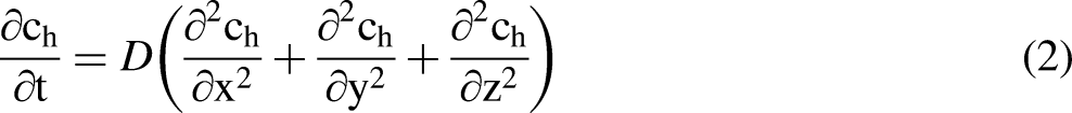
The unsteady hydrogen diffusion can be described based on the three-dimensional Fick's second law,
31
given as
The strains (εD and εσ) induced by hydrogen swelling and mechanical stress, respectively, constitute the total strain (ε) of rubber under the HP hydrogen environment. The components of the total strain can be expressed as


Then, the thermo-mechanical coupling module in ABAQUS software can be used as the first step of the hydrogen diffusion-mechanical comprehensive analysis to simulate the effect of hydrogen swelling on the contact mechanics of rubber seals.
Governing equations of hydrogen diffusion
Driven by the chemical potential gradient, the hydrogen diffusion flux (J) can be expressed as
32
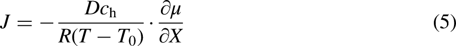

The governing equation of hydrogen diffusion can be obtained


Numerical model
The assumptions of the numerical model are as follows:
The rubber sealing model is a two-dimensional axisymmetric model. The rubber O-ring is installed in a groove that is an analytic rigid body. The hydrogen expansion, diffusion, and solubility coefficients of rubber O-ring are regarded as constants.
Geometric model
The rubber sealing system used in high-pressure hydrogen environments generally comprises rubber O-rings, metal grooves, matched pairs, and polytetrafluoroethylene retaining rings. The typical rubber seal of a single rubber O-ring (namely rubber seal Ⅰ) and the rubber seal with polytetrafluoroethylene backup ring (namely rubber seal Ⅱ) are adopted as the research objective, as shown in Figure 1(a). The geometric models and hydrogen and low-pressure sides (HS, LS) of rubber seals are shown in Figure 1(b). The structural parameters of rubber seals are designed according to GB/T 3452.1, as shown in Table 1.

Schematic diagram of rubber seals: (a) three-dimensional structures and (b) geometric models.
Structural parameters of rubber seals.

Mesh generation and element type
Figure 2(a) shows the partition and meshes of rubber seals without and with the backup ring. The groove is an analytic rigid body without meshing. The quad-dominated type is adopted for meshing the rubber O-rings and backup ring. The global mesh size of the backup ring with a regular shape is set as 0.1 mm. The rubber O-ring is evenly divided into eight parts from the inside to the outside to ensure the mesh quality. The element types of rubber O-ring and backup ring used in mechanical analysis are CAX4RH and CAX4I, respectively, and the element types of rubber O-ring in hydrogen diffusion analysis are DCAX4. To verify the grid independence, the meshing of rubber O-ring is performed with global sizes ranging from 0.02 mm to 0.18 mm, corresponding to the mesh number from 838 to 69203. Under the initial condition, the Von Mises stresses in the center of the O-ring (σm-c) with different mesh numbers are compared in Figure 2(b). The results show that the relative errors of Von Mises stress (σm-c) are less than 0.01% when the mesh number is greater than or equal to 17,087 (i.e., mesh size of 0.04 mm). Therefore, the numerical model of a rubber O-ring with a mesh size of 0.04 mm is adopted in the simulation.

Meshes and verification of rubber seals: (a) partition and meshes and (b) independence verification.
Material parameters and boundary conditions
This study uses nitrile butadiene rubber (NBR), a commonly used sealing material in a hydrogen environment. The parameters (C10, C01, and C20) of the Mooney-Rivlin constitutive model are determined to be 1.096 MPa, 0.809 MPa, and 0.513 MPa, respectively. 25 The elastic modulus and Poisson's ratio of the polytetrafluoroethylene backup ring are 1420 MPa and 0.4, respectively. 34 The friction coefficient between the rubber O-ring, backup ring, and groove is 0.3 and 0.1, respectively, and the friction coefficient between the rubber O-ring, backup ring, and shaft is 0.2 and 0.1, respectively. During the pre-compression process, the fixed constraint is applied to the groove, and x-direction displacement is applied to the shaft according to the pre-compression ratio of the rubber O-ring. After the rubber O-ring is assembled, the hydrogen pressure (p) is applied to the rubber surface exposed to the hydrogen side (HS).
By using the data fitting of the test values 25 and Henry's law (c0 = s·p), the hydrogen diffusion coefficient (D) and solubility coefficient (s) are 3.91 × 10⁻¹⁰ m2/s, and 12.458 wt·ppm·MPa−1, respectively. The hydrogen equilibrium concentration (c0) at different hydrogen pressures can be obtained, specifically c0 = 62.29 ppm, 249.17 ppm, 436.03 ppm, 872.06 ppm, and 1245.8 ppm at p = 5, 20, 35, 70 MPa, and 100 MPa, respectively. In the hydrogen-induced swelling analysis, the equivalent dimensionless concentration at the HS of the rubber surface is set as p/100, and the equivalent dimensionless expansion coefficient (αD) of rubber seals is 0.05. In the hydrogen diffusion analysis, the hydrogen equilibrium concentration (c0) is applied to the boundary concentration (cb) at the HS, and the constrained-boundary diffusion condition is applied to the low-pressure side (LS) of the rubber surface.
Simulation process
The hydrogen diffusion-mechanical sequential numerical simulation of rubber seals in the HP environment is performed using ABAQUS/Standard software.
Firstly, the mechanical finite element models of rubber seals without and with a backup ring are established. The deformation characteristics and stress distribution of the rubber O-ring and backup ring under pre-compression and hydrogen pressure are calculated. Considering the hydrogen swelling effect of rubber, the analysis result of the equivalent concentration field represented by the temperature field in the rubber O-ring is imported into the model as a predefined field. The hydrogen swelling-mechanical coupling analysis is carried out under pre-compression and pressurization to study the contact mechanics of the assembled rubber seals with swelling in the HP environment. Secondly, the obtained O-ring deformation results are extracted as the geometric model and predefined field of the subsequent hydrogen diffusion analysis. The hydrogen diffusion and solubility coefficients of rubber are set in the material properties, and normalized concentration conditions of the boundary and the stress factor are applied. The hydrogen diffusion analysis induced by the stress gradient and concentration gradient of the rubber O-ring is conducted. Furthermore, the influences of hydrogen pressure on the mechanical properties and hydrogen concentration of the rubber seals are studied.
Validations
The mechanical analysis methods are applied to the physical models and boundary conditions in the literature 21 to verify the numerical accuracy. The comparisons of the literature results and the simulated results by using the numerical method in this study are shown in Figure 3. For the mechanical properties in the O-ring, the distributions of the typical stress and strain (σp-max, εp-max) of the O-ring by using the method in this study are consistent with those in the literature. 25 The maximum relative errors of the typical stress and strain (σp-max, εp-max) at the center of the O-ring do not exceed 6% under two operating conditions of pre-compression and pressurization within the allowable range. Moreover, the hydrogen diffusion-mechanical sequential numerical model has been effectively applied in the previous studies of other materials. 35 Therefore, the numerical methods in this study are suitable for predicting the hydrogen diffusion and mechanical properties of rubber seals in the HP hydrogen environment.
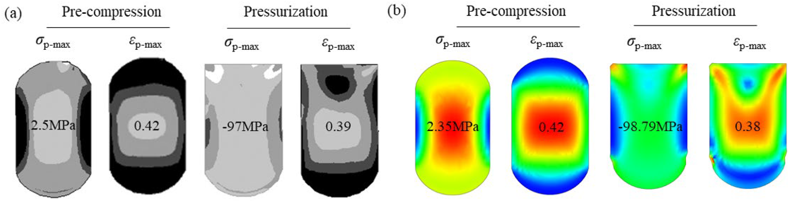
Validations of mechanical properties.
Results and discussion
Mechanical properties of rubber seals with hydrogen swelling
The mechanical properties and sealing performance of non-swelling and swelling rubber seals are studied under the initial conditions of hydrogen pressure p = 70 MPa and the pre-compression ratio a = 20%. Since the rubber is reported to crack and shear failure during the hydrogen environment test,9,36 the distribution characteristics of Von Mises stress (σm), shear strain (εl), and contact stress (pc) of the rubber O-ring are mainly analyzed.
Figure 4 shows the contours of Von Mises stress (σm) and shear strain (εl) in the rubber seals with non-swelling and swelling after pre-compression and pressurization. For the single rubber O-ring Ⅰ (rubber seal Ⅰ), the Von Mises stress (σm) and shear strain (εl) both reach the peak values near the outer groove fillet, and the difference of Von Mises stress (σm) in the O-ring Ⅰ reaches 22.2 MPa under the HP environment. Considering the swelling of rubber after hydrogen absorption, the increase in rubber volume causes additional swelling stress and strain of the O-ring Ⅰ. Since the strain induced by hydrogen diffusion is proportional to the increase in hydrogen concentration, the effect of rubber swelling on the mechanical properties of the O-ring Ⅰ can be obviously found. The maximum Von Mises stresses (σm-max), and shear strains (εl-max) with swelling are 12.3% and 2.9% larger than that with non-swelling, respectively. The swelling rubber O-ring Ⅰ subjected to the groove compression and high-pressure environment is easy to slip and squeeze into the sealing clearance. Therefore, the rubber O-ring may cause fatigue failure and crack due to stress concentration and extrusion deformation in the sealing clearance. For the rubber seal with backup ring (rubber seal Ⅱ), the distribution of Von Mises stress (σm) in the O-ring Ⅱ is more symmetrical radially, and the maximum Von Mises stress (σm-max) of the rubber seals appears near the sealing clearance of the backup ring. The setting of the backup ring reduces the maximum Von Mises stress (σm-max) of the O-ring Ⅱ by 22.4%, which weakens the stress concentration of the rubber O-ring.

Contours of Von Mises stress and shear strain in rubber seals with non-swelling and swelling.
Three characteristic sections (A-A, B-B, C-C) of the O-rings along the axis (y direction) in Figure 4 are chosen. The variations of Von Mises stress (σm) and shear strain (εl) with the radial width (rw) on the three characteristic sections of single O-ring Ⅰ of rubber seal Ⅰ and the O-ring Ⅱ of rubber seal Ⅱ are shown in Figure 5. The absolute values of Von Mises stress (σm) and shear strain (εl) with swelling are generally higher than those with non-swelling on the three sections. As the cross-section moves from the HS to the LS, the Von Mises stress (σm) gradually changes from an apparent hump-type distribution to a uniform distribution. Two different peaks of Von Mises stress (σm) are arranged on both sides of the center in Sections A-A and B-B. Due to the extrusion tendency, the Von Mises stress (σm) in Section A-A reaches the maximum near the sealing clearance side and decays rapidly to both sides. Under the compression of the groove and the shaft, the Von Mises stresses (σm) in the center of Section B-B reach more than 13.4 times and 7.2 times those in the center of Section A-A, respectively, for non-swelling and swelling. The shear strain (εl) on the three sections changes alternately along the radial direction, and the maximum shear strain (εl-max) is located in Section A-A near the LS of the O-ring. This is because the rubber O-ring tends to be squeezed into the sealing clearance under hydrogen pressure and groove compression, while the O-ring at the inner groove fillet is subjected to the shear action in the opposite direction. The shear strain (εl) decreases to the HS and gradually transitions to the opposite alternating change. The critical point when the shear strain (εl) is close to 0 is at about rw = 0.5ho after pressurization. For the two O-rings, the more symmetrical distribution results in the radial maximum values of Von Mises stress (σm) and shear strain (εl) of the O-ring Ⅱ smaller than those of the O-ring Ⅰ except for Section C-C near the HS. Especially for Section B-B in the middle of the O-ring, the maximum shear strain (εl -max) of the O-ring Ⅱ decreases by 34.2% compared to that of the O-ring Ⅰ. The squeezing morphology of the O-ring Ⅱ under the HP environment is improved for the rubber seal Ⅱ.

Radial variations of Von Mises stress and shear strain in O-rings.
Figure 6 shows the distribution of contact stress (pc) along the sealing surfaces (I→II→III) of rubber O-rings with swelling and non-swelling. The O-rings are in close contact with the groove and the shaft after pressurization, and the formation of sealing surfaces I, II, and III reduces the possibility of hydrogen leakage through the inner and outer sides. The contact stresses (pc) are approximately symmetrically distributed along the contact length. Due to the larger inner fillet radius than the outer fillet radius, the length of sealing surface I at the inner diameter (ID) is slightly larger than that of sealing surface III at the outer diameter (OD). The contact stress (pc) near Points a and d at the HS is less than 10 MPa, while the contact stress (pc) increases sharply to more than 75 MPa in the middle of sealing surfaces I and III. The contact stresses (pc) always maintain high values on sealing surface II after pressurization, except for the regions near the inner and outer groove fillets (Points b and c). Especially the contact stress (pc) near the groove fillets of O-ring II attenuates significantly by more than 44% due to the decrease in the compaction degree. So, the maximum contact stresses (pc-max) of both O-rings I and II are higher than the hydrogen pressure (p = 70 MPa) to achieve high-pressure hydrogen sealing, with a slightly larger value of O-ring I than O-ring II. The effective sealing length (Le), where the contact stress (pc) exceeds the hydrogen pressure (p), accounts for about 50% of the total sealing length (L) of the O-rings. Compared with the results with non-swelling, the maximum contact stresses (pc-max) of the O-rings I and II with swelling increase by about 1.5% and 5.0%. For the rubber seal II, the side wall of the backup ring also serves as the sealing surface, and the maximum contact stress (pc-max) on the backup ring reaches 81.7 MPa. Therefore, the rubber seal II can effectively increase the total sealing length and the maximum contact stress and improve the sealing performance.

Contact stress along the sealing surface of O-rings.
Hydrogen concentration distribution of rubber O-ring
It can be seen from equation (9) that the gradient of concentration (ch) and hydrostatic stress (σh) directly affects the hydrogen diffusion behavior of rubber O-ring. Correspondingly, the hydrogen diffuses unevenly through the gaps of the molecular chain in the rubber O-ring. Figure 7 shows the distribution contours and radial variations of hydrogen concentration (ch1 and ch2) in rubber O-rings considering hydrogen swelling under the stress gradient without boundary constraint and the stress-concentration gradient.

Radial distribution of hydrogen concentration: (a) stress-induced diffusion; (b) stress- and concentration-induced diffusion.
For the stress-induced diffusion without boundary constraint (Figure 7(a)), the influence of concentration boundary difference is ignored after stable diffusion. The hydrogen concentrations (ch1) of the O-rings reach the highest near the HS and groove fillets after pre-compression and pressurization. Due to both sides of Section C-C being close to the free surface of the HS, the hydrogen concentration (ch1) in Section C-C appears to concave with a relatively high concentration. The values and changing gradient of hydrogen concentration (ch1) in Section A-A near the LS are lower than those in Section C-C, while the distribution of hydrogen concentration (ch1) in Section A-A shows more obvious radial asymmetry because of the hydrogen enrichment in the inner groove fillet. In contrast, the hydrogen diffusion ability weakens, and the hydrogen concentration decays significantly near the sealing surfaces. Especially on the inner side of section B-B near the middle of the O-rings, the hydrogen concentration (ch1) rapidly drops to the lowest values (about 794 ppm) of the O-rings. It corresponds to the sudden increase in contact stress (pc) in Figure 6. The molecular chain of rubber is squeezed by large contact stress, resulting in the closure of the internal pores and cavities and the reduction of the free volume of the rubber, which hinders hydrogen diffusion in the rubber. The overall hydrogen concentrations (ch1) of O-ring II are slightly lower than those of O-ring I by less than 1.0%, and their relative difference gradually decreases from the LS to the HS. For the stress- and concentration-induced diffusion (Figure 7(b)), the hydrogen diffusion of the O-ring is driven by the concentration difference and the stress gradient, and the concentration difference dominates the hydrogen diffusion. This corresponds to the hydrogen diffusion flux expressed in Equation (9). Affected by the boundary concentration (cb) near the HS, the hydrogen concentration (ch2) decreases significantly from Section C-C to Section A-A. Compared with the stress-induced concentration distribution, the hydrogen concentration (ch2) in Sections A-A and B-B is more evenly distributed along the radial direction, especially for the O-ring II. Due to the edge effect, the hydrogen concentration (ch2) in Section C-C decreases from both sides to the center due to the gradient of the free end. The average value and distribution inhomogeneity of hydrogen concentration in Section C-C of O-ring II exceeds those of O-ring I.
Figure 8 shows the distribution of hydrogen concentration (ch1 and ch2) along the sealing surfaces (I→II→III) of rubber O-rings considering hydrogen swelling. For the stress-induced diffusion without boundary constraint (Figure 8(a)), the hydrogen concentration (ch1) on the three sealing surfaces of the O-rings gradually decreases from the edge to the middle after pre-compression and pressurization. In particular, the hydrogen concentration (ch1) is lowest in the middle of the sealing surface I at the ID. Considering the effect of hydrostatic stress, the hydrogen concentration in the O-ring (ch1) is generally lower than that at the boundary (cb) except for the junction (near Point b) of sealing surfaces I and II in O-ring I. Hydrogen accumulates locally near the inner groove fillet, where the hydrogen concentration (ch1) exceeds the boundary concentration (cb). However, the relatively stable hydrogen concentration distribution below the boundary concentration appears near the sealing clearance. Corresponding to the sudden drop of contact pressure, the hydrogen concentrations (ch1) of surfaces II and III near the sealing clearance for O-ring II exceed those for O-ring I. Generally, the circumferential variation of hydrogen concentration (ch1) of O-ring I is higher than that of O-ring II by 0.3%. For the stress- and concentration-induced diffusion (Figure 8(b)), the hydrogen concentration (ch2) changes significantly and approximately symmetrically along the sealing surfaces. The changing gradient of hydrogen concentration on the sealing surfaces I and III gradually increases from the LS to the HS. It can still be noted that hydrogen is more likely to accumulate near the inner groove fillet of O-ring I.

Hydrogen concentration along the sealing surface of O-rings.
Influence of hydrogen pressure environments
The variations of the Von Mises stress (σm) and shear strain (εl) in rubber seals under different hydrogen pressures (p = 5, 20, 35, 70, 100 MPa) are shown in Figure 9. The characteristic values of Von Mises stress and shear strain, including maximum values (σm-max, εl-max), minimum values (σm-min, εl-min), and the values in the center (σm-c, εl-c) in rubber seals are chosen for comparison.
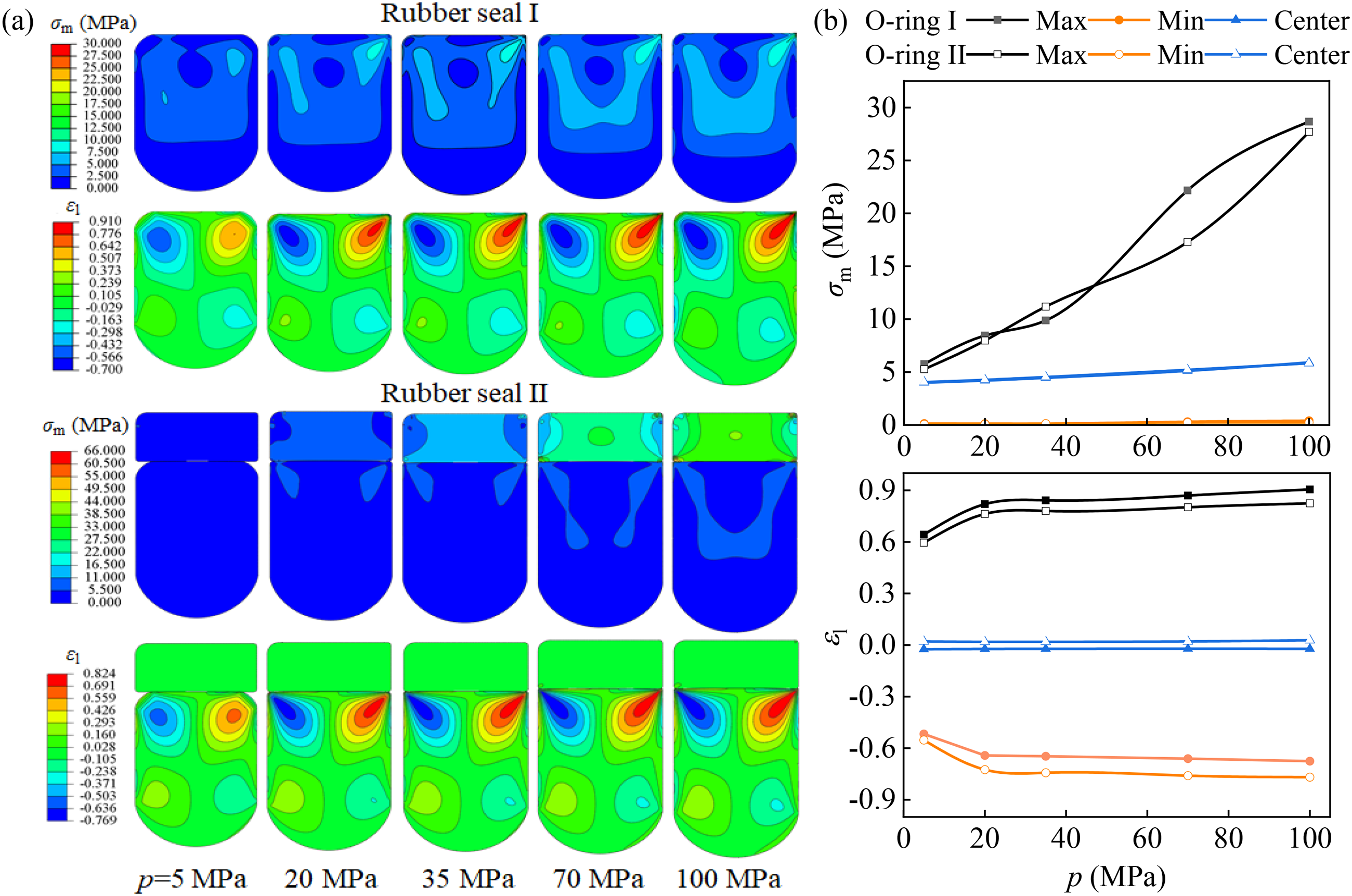
Comparisons of Von Mises stress and shear strain under different hydrogen pressures.
With the increase in hydrogen pressure (p) from 5 MPa to 100 MPa, the hydrogen swelling volumes of rubber increase more obviously, and the peaks of Von Mises stress (σm) gradually shift to the sealing clearance. The maximum values of Von Mises stress (σm-max) in rubber seal I at different pressures increase nearly four times under assembly, pressurization, and hydrogen swelling. The stress concentration and the possibility of fatigue damage in the rubber O-rings increase, and the hydrogen gas may be more easily leaked from defects such as cracks to the outside. The maximum Von Mises stresses (σm-max) of the backup ring of rubber seal II increase by more than eight times with hydrogen pressure (p). Because of the effective transmission of the forces on the O-ring by the backup ring, the maximum Von Mises stresses (σm-max) of O-ring II under high pressure (p ≥ 70 MPa) are lower than those of O-ring I. The maximum and minimum shear strain values (εl-max, εl-min) of the O-rings under five hydrogen pressures appear near the outer and inner groove fillets, respectively. As the hydrogen pressure (p) increases from 5 MPa to 100 MPa, the maximum shear strains (εl-max) and absolute value of minimum shear strains (εl-min) increase by 40.9% and 30.7% for the O-ring I and 38.5% and 39.1% for the O-ring II, respectively. Affected by a higher gradient of hydrogen pressurization and larger swelling volume, the extrusion deformation of rubber O-rings aggravates, and the rubber O-rings are more prone to shear failure in the HP environment. Among the five hydrogen pressure conditions, the maximum values and non-uniformities of shear strain in O-ring I are greater than those of O-ring II, and their relative difference of maximum shear strains (εl-max) reaches its maximum of 8.9% at p = 100 MPa. The backup ring in the rubber seal II can effectively reduce the shear damage of the O-ring II.
The variations of contact stress (pc) along the sealing surface (I→II→III) of rubber O-rings under different hydrogen pressures are shown in Figure 10. The changes in sealing lengths (L and Le) and effective sealing rates (E) with the hydrogen pressures are shown in Figure 11. The contact stresses (pc) of the O-rings under five hydrogen pressures can exceed the hydrogen pressure (p) on all three sealing surfaces I, II and III. The swelling O-ring fits the groove more tightly, and the contact stress (pc) of the sealing surfaces increases with the increase in hydrogen pressure (p). When the hydrogen pressure p = 5 MPa, the rubber O-rings are not entirely squeezed to the inner and outer groove fillets (near Points b and c), resulting in a contact stress of 0 within a specific range. As the hydrogen pressure (p) increases to 20 MPa, the O-ring I has been completely attached to the inner groove fillet, and the O-ring I at the outer groove fillet and the O-ring II at the inner and outer groove fillets are close to the critical state of full contact. Under the high hydrogen pressure (p ≥ 35 MPa), the O-ring I releases a small amount of contact stress at the clearance near the outer groove fillet, while the contact pressure at the inner and outer groove fillets of the O-ring II decays rapidly compared to O-ring I. It makes the maximum and average contact pressures of O-ring II slightly lower than those of O-ring I. The total sealing lengths (L) increase by 27.2% and 26.3% with the hydrogen pressure (p) from 5 MPa to 100 MPa, respectively, for the O-ring I and O-ring II. However, the effective sealing length (Le) of O-ring II under the hydrogen pressure p = 5 MPa exceeds that under the hydrogen pressure p = 100 MPa, resulting in an effective sealing rate (E) larger than 63.5%. When the hydrogen pressure (p) increases to 20 MPa, the effective sealing length (Le) decreases to the minimum under five hydrogen pressures, which greatly weakens the sealing effect of the rubber O-ring. The effective sealing rates (E) of the two O-rings gradually decrease at p ≥ 20 MPa with the range of 50∼52%.
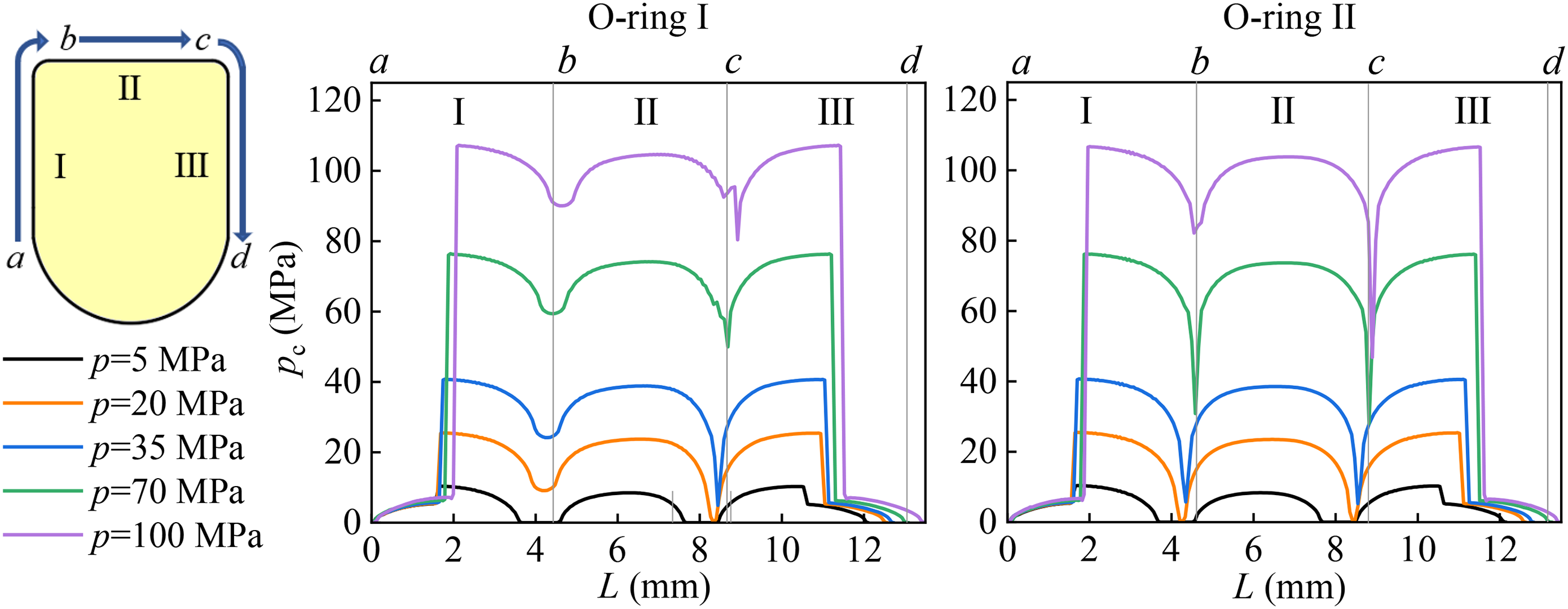
Comparisons of contact stresses under different hydrogen pressures.

Comparisons of sealing lengths under different hydrogen pressures: (a) total sealing length; (b) effective sealing length.
The variations of relative hydrogen concentration (Δch1 = ch1-cb, Δch2 = ch2-cb) along the sealing surfaces (I→II→III) of rubber O-rings under different hydrogen pressures (p) and two kinds of gradient conditions are shown in Figure 12. The initial concentration boundaries (cb) of the O-rings at the HS are 62.29 ppm, 249.17 ppm, 436.03 ppm, 872.06 ppm, and 1245.8 ppm, respectively under the hydrogen pressure p = 5, 20, 35, 70, and 100 MPa.

Comparisons of hydrogen concentration under different hydrogen pressures.
Similar variations of relative hydrogen concentration (Δch1 or Δch2) along the sealing surfaces appear under different hydrogen pressures. For the stress-induced diffusion without boundary constraint, the changing gradient of relative hydrogen concentration (Δch1) increases with the hydrogen pressure (p). As the hydrogen pressure (p) increases from 5 MPa to 100 MPa, the peak-valley amplitudes of relative hydrogen concentration (Δch1) change by 19 and 20 times, respectively, for the O-ring I and O-ring II. The hydrogen enrichment phenomenon near the hydrogen side and the inner groove fillet of the O-ring I becomes more pronounced, accompanied by the expansion of the area. The maximum hydrogen concentration (ch1) of the O-ring I at p = 100 MPa is 6.9 ppm higher than the boundary concentration (cb). The hydrogen concentration (ch1) along the sealing length of O-ring II under five hydrogen pressures is generally lower than that of O-ring I, except at the outer groove fillet. For the stress- and concentration-induced diffusion, the change of relative hydrogen concentration (Δch2) at the ID is slightly slower than that at the OD under five different hydrogen pressures due to the more extended sealing length of surface I than surface II. However, the hydrogen concentration gradient at the inner groove fillet of the O-ring I becomes more evident as the hydrogen pressure (p) increases. With the increase in hydrogen concentration (ch2) under high hydrogen pressure, the possibility of hydrogen leaking through the O-rings will increase, and the phenomenon of hydrogen-induced degradation of materials also intensifies.
Multi-factor significance assessment
According to the above results of contact mechanics and hydrogen diffusion characteristics, the rubber seal II with better sealing performance is adopted for further optimization. The study employs an orthogonal experimental method and comprehensive frequency analysis method to assess the significant impacts of the main structural and assembly parameters on rubber seal II and obtain the optimal structural parameters of the rubber seal under the hydrogen pressure p = 70 MPa.
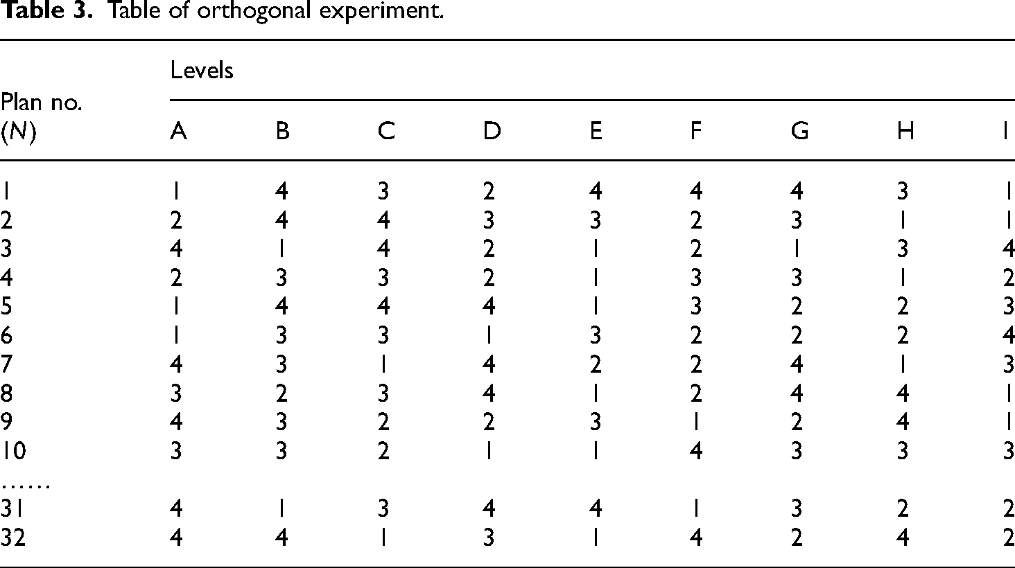
Considering the requirements of the HP hydrogen environment on the reliability and durability, sealing performance, and the weakening of extrusion tendency for rubber seals, the maximum contact stress (pc-max), the maximum Von Mises stress (σm-max), and the maximum shear strain (εl-max) of the O-ring II are determined as the optimization indexes. Under the premise of ensuring that the maximum contact stress (pc-max) is higher than the hydrogen pressure (p), the three optimization objectives should be reduced as much as possible. According to the standards GB/T 3452.1-2005, GB/T 3452.3-2005, and GB/T 3452.4-2020, the study has identified nine adjustable factors for investigation, including the diameter of O-ring (D0), pre-compression ratio (a), groove width (b1), inner fillet radius (R2), outer fillet radius (R1), axial width of backup ring (b2), outer fillet radius of backup ring (R3), coefficient of friction (f) and sealing clearance (h), focusing on the structures of O-ring, groove, backup ring, and assembly state. The specific factors are denoted in A∼I in sequence, and four experimental levels are set for each factor, as shown in Table 2. The designed orthogonal table L32(49) is shown in Table 3.
Factors and levels of orthogonal experiment.

Table of orthogonal experiment.
Based on the above orthogonal array, the three optimization target parameters (pc-max, σm-max, and εl -max) of the O-ring are calculated and presented in Figure 13. It can be seen that the results obtained from Plan No. 12, among the 32 orthogonal schemes can meet the optimization requirements of three objectives. The combinations of factor levels of A3B3C1D3E4F3G1H2I1 can be adopted as a multi-objective optimization scheme Ⅰ. The corresponding structural parameters of rubber seals are as follows: the diameter of O-ring D0 = 3.55 mm, pre-compression ratio a = 20%, groove width b1 = 8 mm, inner fillet radius R2 = 0.7 mm, outer fillet radius R1 = 0.3 mm, axial width of backup ring b2 = 1.8 mm, outer fillet radius of backup ring R3 = 0.1 mm, coefficient of friction f = 0.1, and sealing clearance h = 0.03 mm.

Comparison of orthogonal experimental results.
Given the comprehensive comparability of multiple factors, the range analysis is carried out on the orthogonal experimental results. The range R denotes the influence of various factors, and the optimal level can be identified based on the average values k of the orthogonal results, given as
37


The average values ki of the three sealing parameters (pc-max, σm-max, and εl -max) under level i of each factor and the corresponding ranges R are represented in Table 4 and Figure 14. The ranges are ranked according to the values, and the larger the range value, the more significant the impact of the structural factor on the rubber sealing performance parameter. On the one hand, the maximum contact stress (pc-max) for all test conditions exceeds 70 MPa, ensuring effective O-ring sealing. The impact of the factors on the maximum contact stress (pc-max) is ranked as B(a) > H(f) > A(D0) > C(b1) > F(b2) > I(h) > G(R3) > E(R1) > D(R2). The maximum contact stress (pc-max) increases obviously with the pre-compression ratio (a), while other factors have a small impact on pc-max, ranging from 75 to 77 MPa. On the other hand, reducing the Von Mises stress and shear strain helps to mitigate the risk of stress concentration, crack, and shear tear of rubber seals. The impacts of the factors on the maximum Von Mises stress (σm-max) and the maximum shear strain (εl -max) are ranked as G(R3) > A(D0) > B(a) > C(b1) > D(R2) > E(R1) > F(b2) > I(h) > H(f) and G(R3) > H(f) > I(h) > A(D0) > F(b2) > B(a) > E(R1) > C(b1) = D(R2), respectively. The outer fillet radius of the backup ring (R3) has the most significant impact both on the maximum Von Mises stress (σm-max) and the maximum shear strain (εl -max), and the maximum Von Mises stress (σm-max) and the maximum shear strain (εl-max) increase significantly with the outer fillet radius of the backup ring (R3). The influence of the diameter of O-ring (D0) on the maximum Von Mises stress (σm-max) and the maximum shear strain (εl-max) is also at the forefront of nine factors, and the variation curves of the maximum Von Mises stress (σm-max) and the maximum shear strain (εl-max) both have a minimum value at D0 = 2.65 mm.

Relation curves between sealing performance parameters and various factors.
Range analysis of orthogonal results.

Based on the above intuitive analysis and range analysis results, the optimal levels of various factors vary significantly for each objective (pc-max, σm-max, and εl-max). The challenges of strong coupling between multi-parameters in the design process of rubber seals make it difficult to obtain the optimal scheme for high-pressure hydrogen environments only through single-objective optimization. In recent years, the increasingly mature multi-objective optimization algorithm has been widely used in sealing design and engineering fields with the advantages of high optimization efficiency, strong adaptability, and convenient use.38,39 Therefore, the introduction of a suitable multi-objective optimization method can effectively improve the comprehensive sealing performance of rubber seals and is convenient for reference in the engineering design of rubber seals in high-pressure hydrogen environments.
The comprehensive frequency analysis method 40 is used to determine the optimal test scheme for the multi-objective optimization of O-ring performance under the HP environment. Under the condition that the test indexes are equally important, the level with the highest frequency is adopted according to the number of times the level appears. If the frequency is the same or similar, the final level is determined based on the operational feasibility, cost, and other aspects. The level frequency of each factor considering multiple objectives can be obtained, as shown in Table 5. Considering the comprehensive frequency and the overall structure of rubber seals, the combinations of factor levels of A2B1C1D2E2F3G1H2I3 are adopted as a multi-objective optimization scheme Ⅱ. The corresponding structural parameters of rubber seals are as follows: the diameter of O-ring D0 = 2.65 mm, pre-compression ratio a = 10%, groove width b1 = 8 mm, inner fillet radius R2 = 0.5 mm, outer fillet radius R1 = 0.2 mm, axial width of backup ring b2 = 1.8 mm, outer fillet radius of backup ring R3 = 0.1 mm, coefficient of friction f = 0.1 and sealing clearance h = 0.11 mm.
Comprehensive frequency analysis of factor levels.

The performance index results of the rubber seals with the two optimal schemes (Ⅰ and Ⅱ) from intuitive analysis and comprehensive frequency analysis are calculated and analyzed as shown in Figure 15. Compared with the results of original rubber seals, the maximum contact stress (pc-max), the maximum Von Mises stress (σm-max), and the maximum shear strain (εl-max) of the O-rings decrease by 0.8%, 2.5%, and 3.8% for optimal scheme Ⅰ, and 3.8%, 14.7%, and 0 for optimal scheme Ⅱ respectively. The maximum contact stress (pc-max) and the maximum Von Mises stress (σm-max) of the O-ring are improved more obviously for optimal scheme Ⅱ, while the maximum shear strain (εl-max) of the O-ring is improved more obviously for optimal scheme Ⅰ. Therefore, both optimization schemes Ⅰ and Ⅱ can achieve the optimization goal and reduce the probability of wear and failure for the rubber seals.

Comparisons of optimal and original indexes.
Conclusions
In this study, a numerical procedure for the analysis of rubber O-ring seals considering swelling is developed using the finite element method in ABAQUS software. The sealing performance and hydrogen concentration field of typical rubber seals with/without a backup ring are investigated under conditions of hydrogen swelling, stress-concentration gradient, and HP environment. The effects of environmental pressure and backup ring on Von Mises stress, shear strain, contact stress, and hydrogen concentration distribution of the O-ring are considered in the simulations. Finally, the impact significance evaluation and multi-objective optimization of the main structural, and assembly parameters are conducted to obtain the optimal schemes of the rubber seals under the HP environment. The conclusions can be summarized as follows:
Hydrogen swelling significantly affects the mechanical properties and extrusion tendency of rubber O-rings. The backup ring in the rubber seals can effectively increase the total sealing length (L) and reduce the maximum Von Mises stress (σm-max) of the rubber O-ring. Under the hydrogen pressure p = 70 MPa and pre-compression ratio a = 20%, the effective sealing length (Le) of the O-ring accounts for about 50% of the total sealing length (L). The diffusion near the HS of the O-ring is mainly driven by the concentration difference and stress gradient, with the concentration difference being the more significant factor. Hydrogen is more likely to accumulate near the inner groove fillet of the single O-ring I than that of the O-ring with a backup ring. As the hydrogen pressure (p) increases from 5 MPa to 100 MPa, the total sealing length (L) of the O-ring prolongs, and the maximum Von Mises stress (σm-max) near the sealing clearance increases nearly four times. However, the effective sealing rates (E) of the two O-rings drop sharply when p ≥ 20 MPa, and the possibility of hydrogen leaking through the O-ring increases. Two multi-objective optimization schemes (A3B3C1D3E4F3G1H2I1, A2B1C1D2E2F3G1H2I3) for the main structural and assembly parameters of rubber seals are proposed under hydrogen pressure p = 70 MPa. After optimization, the maximum contact stress (pc-max), the maximum Von Mises stress (σm-max), and the maximum shear strain (εl-max) of the O-rings can be improved compared with the original O-ring.
Based on the above numerical method and procedure for the rubber seals, the influence of material parameters by the rubber manufacturing, high-pressure hydrogen aging, chemical exposure, and other operating parameters such as pressure and temperature fluctuations on the comprehensive sealing performance of rubber seals will be considered in the further study, so as to form a multi-field coupling numerical method of rubber seals which is more in line with the actual hydrogen application environment. Moreover, a small-scale mechanism test device for rubber seals that simulates the hydrogen environment and the assembly state can be built as much as possible to more accurately reflect the actual sealing situation of rubber seals and verify the simulation results.
Footnotes
Author contribution
YM and XP: conceptualization; YM and XD: investigation, methodology; XW: software, data curation; YM and XW: formal analysis; YM and XD: writing—original draft preparation; XP: resources; YM and XM: writing—review and editing; XM: supervision; YM: funding acquisition. All authors have read and agreed to the published version of the manuscript.
Declaration of conflicting interests
The authors declared no potential conflicts of interest with respect to the research, authorship, and/or publication of this article.
Funding
The authors disclosed receipt of the following financial support for the research, authorship, and/or publication of this article: This work was supported by the National Natural Science Foundation of China (grant numbers: 52375211, 51975527).