
Abstract
This study aims to investigate the impact of isolation piles on soil vibrations in the environment surrounding suburban railways. Initially, a comprehensive numerical model of the train was established to simulate the wheel-rail interaction forces, which were then applied to a three-dimensional coupled track-soil model. The accuracy of the model was validated through comparison with measured data. The focus of the research is to analyze the vibration isolation effects of single-row, double-row, and triple-row piles, with particular attention to the influence of pile spacing in double-row piles on isolation effectiveness. The study found that the effectiveness of isolation piles in reducing soil vibration acceleration within a depth range of 0 m to 2 m decreases as the pile spacing increases. When the pile spacing reaches 2 times the pile radius, single-row piles exhibit the best vibration isolation effect. For reducing peak soil acceleration within a depth range of 4 m to 8 m, single-row piles are most effective when the pile spacing exceeds 1 times the pile radius. To attenuate peak soil acceleration at depths greater than 6 m, the pile spacing for single-row and double-row piles should be set at 0.5 times the pile radius, while triple-row piles should have a spacing of 1 times the pile radius. In terms of reducing peak soil velocity, single-row piles demonstrate better vibration isolation effects. To reduce peak velocity in soil at depths greater than 2 m, the pile spacing for single-row and double-row piles should be set at 0.5 times the pile radius, while triple-row piles should be spaced at 1 times the pile radius. For reducing peak soil displacement, single-row piles should be used, with optimal results achieved at a spacing of 1 times the pile radius.
Introduction
The vibrations induced by rail transit significantly disturb human life and work and, in severe cases, can even lead to the destruction of buildings.1–4 Typically, these issues are addressed through active and passive vibration isolation methods5,6 Active vibration isolation systems are commonly employed to isolate vibration sources from the ground,7,8 while passive vibration isolation systems are frequently used to reduce the energy transmitted to structures. 9 This approach avoids altering the dynamic characteristics of the vibration source and the structure, thereby preventing potential safety issues at these locations. Passive vibration isolation methods can be broadly categorized into pile isolation and trench isolation techniques.10–12 Extensive theoretical research and engineering practice have been conducted on pile isolation methods, revealing that isolation piles can effectively isolate environmental vibrations13,14 and reduce the energy of vibrations transmitted to structures.15,16 Consequently, isolation piles are widely applied in vibration mitigation measures. 17
Various methods are currently employed to study the vibration isolation effects of row piles 18 including field experiments, model tests, and numerical simulation methods. Field experiment results are authentic and reliable,19,20 yet they are challenging to coordinate, are costly, and involve significant environmental disturbances. 21 Model tests, based on similarity principles, employ scaled models and yield relatively authentic and reliable results. However, these systems require substantial floor space and entail high costs for construction, operation, and maintenance.22,23 Numerical simulation, which uses computers to approximate model solutions, requires validation through field experiments or model tests. Nonetheless, numerical simulation presents no coordination difficulties, has no land requirements, and offers adjustable and controllable testing costs, 24 making it a widely adopted research method.25–29 Zhang 30 employed a finite element model to analyze the vibration reduction performance of periodic piles under subway ground source impact. Using the measured vibration source intensity as the excitation input, the study investigated the influence of different burial depths and row numbers on the damping effect of the piles. Wang et al. 31 established a coupled model of moving vehicle loads and subsoil construction structures, finding that the ground vibration in sensitive areas induced by moving vehicle loads is primarily vertical and low-frequency, with the main frequency range being 3 to 4 Hz, consistent with ground pulsation tests. Zhang et al. 32 utilized the finite element analysis software ANSYS to analyze the vertical ground vibration amplitude behind a single row of cast-in-place concrete thin-walled pipe piles and investigated its influencing factors.
However, previous studies have mainly focused on the attenuation of surface vibrations, with less attention given to their impact on underground soil vibrations.33–37 With the rapid urbanization in China and the extensive construction of underground structures (such as basements, underground parking lots, and underground shopping malls), studying soil vibrations has become increasingly important. Therefore, this paper combines numerical analysis and finite element methods to establish a coupled train-tunnel-soil model. The study analyzes the vibration isolation effects of isolation piles on peak acceleration, velocity, and displacement in the time domain under various influencing factors and explores the impact of pile spacing at different pile radii on soil vibrations (as shown in the process in Figure 1).

Technical roadmap.
Model validation
The model establishment in this study involves three steps. First, a numerical model of the train was developed using Intel Visual Fortran to calculate the wheel-rail interaction forces. 38 Second, a finite element model of the rail-tunnel-soil coupling system was established. Third, the calculated wheel-rail interaction forces were applied to the finite element model.
Wheel-rail interaction force modeling
The train model adopts a two-degree-of-freedom suspension train model, where the vertical and pitch degrees of freedom are considered for both the car body and the bogie, while only the vertical degree of freedom is considered for the wheels. The primary suspension consists of a spring k1s and a damper c1 in series, which is then in parallel with another spring k1p; the secondary suspension consists of a spring k2p and a damper c2 in parallel. Therefore, the complex stiffness of the suspension is expressed as:39,40


The sleeper layer is still manufactured using the Euler beam model along the x-direction but without bending stiffness. Therefore, the motion equation is given by:

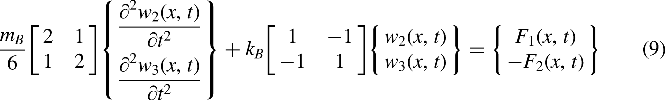
In equations (7)–(9), EI, kB, and kp are complex numbers, with their imaginary parts representing the respective damping coefficients.
The vertical vibration of the wheel generates a series of wheel-rail interaction forces that vary harmonically with time at the wheel-rail contact point. These forces can be represented as

The representation of the track displacement amplitude under the action of resonant wheel-rail forces P(t) at the wheel-rail contact point is given by:

During regular train operation, the wheel and rail remain in contact. By considering the continuity of vertical displacements between the wheel and rail, the wheel/rail interaction forces can be solved. The vertical displacement of the wheel axle is composed of the Hertz spring compression, wheel/rail irregularities, and vertical deformation of the rail. It can be expressed as follows:

Substituting equation (11) and zW1/ zW2/ zW3/zW4 into equation (12), the expression for the wheel-rail interaction force can be obtained as follows.
38

Finite element model establishment
The measurement site was selected near Kaifa Avenue in Taizhou, Zhejiang Province, China (as shown in Figure 2), with data collected on the morning of April 28, 2023. The train was operating at a speed of 16.9 m/s.
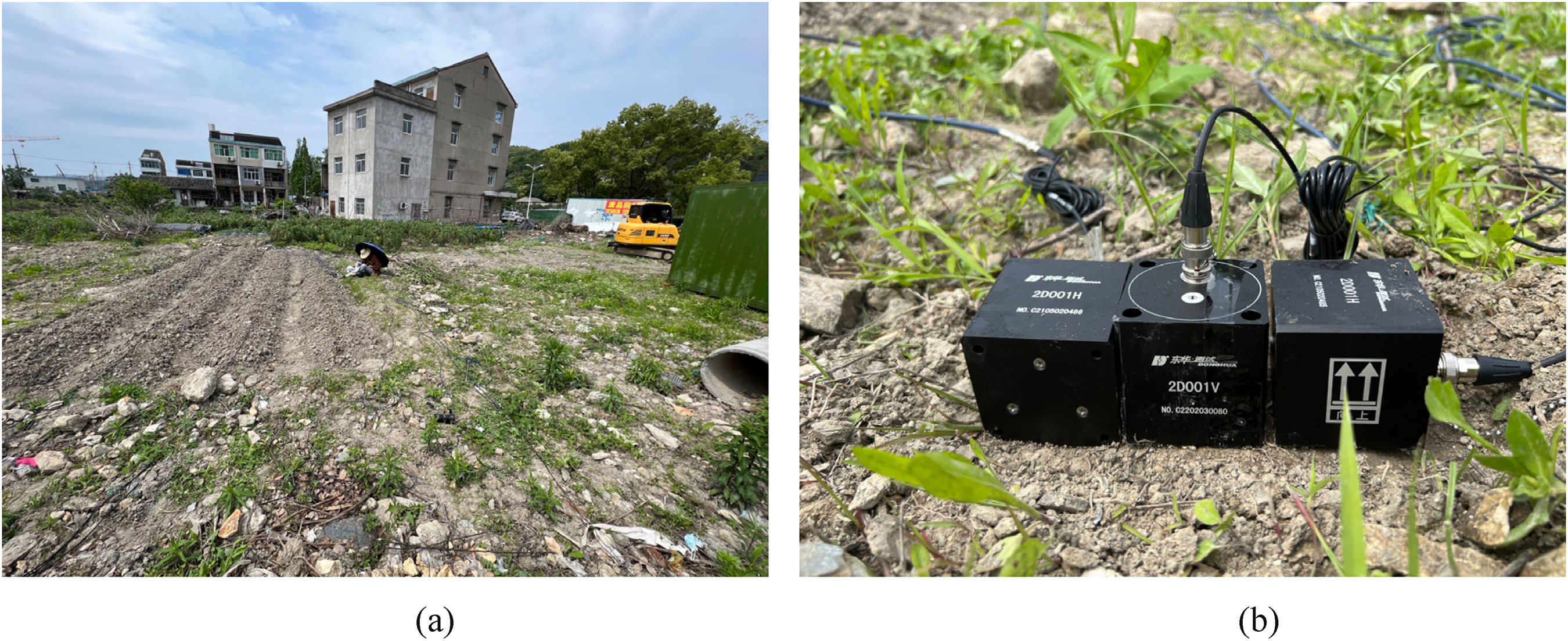
Schematic diagram of on-site measurements. (a) Map of the observation site. (b) Observation instruments.
The selected tunnel cross-section includes seven layers of soil. In the field data collection, six measurement points were arranged, with each point spaced 10 m apart. Additionally, the tunnel train is 93 m long, with a tunnel burial depth of 23 m, an outer diameter of 8.5 m, and an inner diameter of 7.7 m. The tunnel depth ratio is approximately 3d, as shown in Figure 3. Consequently, the finite element model size was chosen to be 200 m long, 100 m wide, and 30 m deep, as depicted in Figure 4.

Schematic diagram of tunnel cross-section structure.

Schematic diagram of finite element model.
Considering that the vibrations induced by the train result in small-strain deformations that do not produce plastic strain, an elastic model was adopted. To reduce computational costs, a linear elastic constitutive model was used for the soil. The rails were modeled using beam elements, and the track slabs were modeled using plate elements. The model was meshed using 10-node tetrahedral elements, comprising a total of 123,631 elements.
In reality, soil can extend infinitely. However, when applying finite element methods, a specific range of soil is artificially selected, introducing artificial boundaries on the front, back, sides, and bottom of the model. These boundaries can cause reflections of vibrations, which do not align with actual conditions. To minimize wave reflections near the boundaries, viscoelastic boundary conditions were applied at the model boundaries. All surfaces, except the ground surface, are fully constrained, and viscoelastic artificial boundaries are used to ensure the absorption of stress waves.
The contact relationships between the soil layers are set as rigid connections. The interfaces between the soil layers are continuous, meaning that stress and strain are continuously transmitted between the layers without significant separation or slippage. The calculated wheel-rail forces were applied as concentrated external loads to the finite element model of the track. This was achieved by gradually moving the position of the wheel-rail forces at different time steps. The Newmark-β method was used in solving the model. This method strikes a balance between stability and accuracy, making it suitable for most dynamic problems. The soil layer parameters were derived from geological survey data at the measurement site, as shown in Table 1.
Calculation parameters of the soil layer in the suburban railway underground section.

Model validation
To facilitate model validation, measurement points were set up both on the ground surface and inside the tunnel in the underground section of the suburban railway for data collection. The spatial relationships between the measurement points are shown in Figures 3 and 5, with a spacing of 30 m between the centerlines of the two tunnels. Data were collected using Donghua 2D001 accelerometers, which have a sensitivity of 0.3 V·s²/m and a maximum range of 20 m/s². The data acquisition equipment used was the Donghua DH5922D dynamic signal testing and analysis system.

Schematic of measurement points on the site.
Since impulse loads have a broad frequency range, they can more comprehensively verify the model's reliability compared to simple harmonic loads. Therefore, a unit impulse load was applied to the center of the model's top surface, and the acceleration impulse response at the application point was obtained (as shown in Figure 6). Figure 6 shows that in the latter part of the response, the acceleration essentially returns to zero, indicating that the model has good reliability.

Acceleration impulse response.
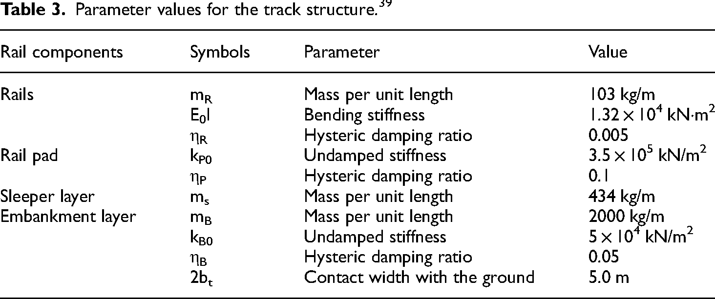
The wheel-rail interaction forces were calculated based on the vehicle parameters in Table 2 and the track structure parameters in Table 3, and these forces were applied to the track in the finite element model. The maximum vertical vibration levels obtained from the model calculations were then compared with the maximum vertical vibration levels from the measured data to validate the model's reliability, as shown in Figure 7 and Table 4.

Comparison of maximum Z-vibration levels.
Parameter values for the vehicles. 39

Parameter values for the track structure. 39
Comparison of maximum Z-vibration levels.

Analysis of vibration isolation effect of vibration isolation piles in time domain
To facilitate the analysis of the impact of isolation piles on soil vibrations under different factors, the number of pile rows and pile spacing were selected as the two variables for this study. The pile rows were set as single-row, double-row, and triple-row configurations. The pile radius was uniformly set to 1 m, and the pile spacing was set to 0.5 times, 1 time, 1.5 times, and 2 times the pile radius. Measurement point P6 was selected as the comparison point, with the edge of the isolation piles located 3 m from the tunnel. For clarity in analysis, we defined the legend in the figures such that the first digit represents the number of pile rows, and the second digit represents the pile spacing as a multiple of the pile radius. For example, “2-1.5” indicates a double-row pile configuration with a spacing of 1.5 times the pile radius. Additionally, the arrangement of the double-row and triple-row piles is shown in Figure 8. Additionally, in Figure 9, we present the time history of vibration acceleration at different depths of soil without isolation walls.
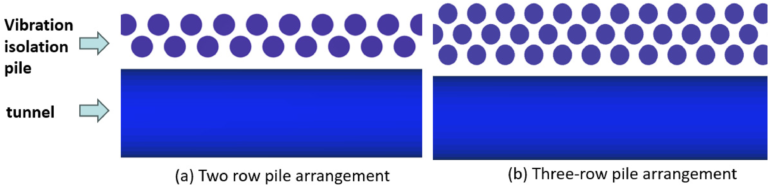
Arrangement of piles. (a) Two row pile arrangement. (b) Three-row pile arrangement.

Time history of vibration acceleration at different depths of soil without isolation piles. (a) 0 m. (b) −2 m. (c) −4 m. (d) −6 m. (e) −8 m. (f) −10 m.
Peak acceleration vibration isolation effect analysis of vibration isolation piles in time domain
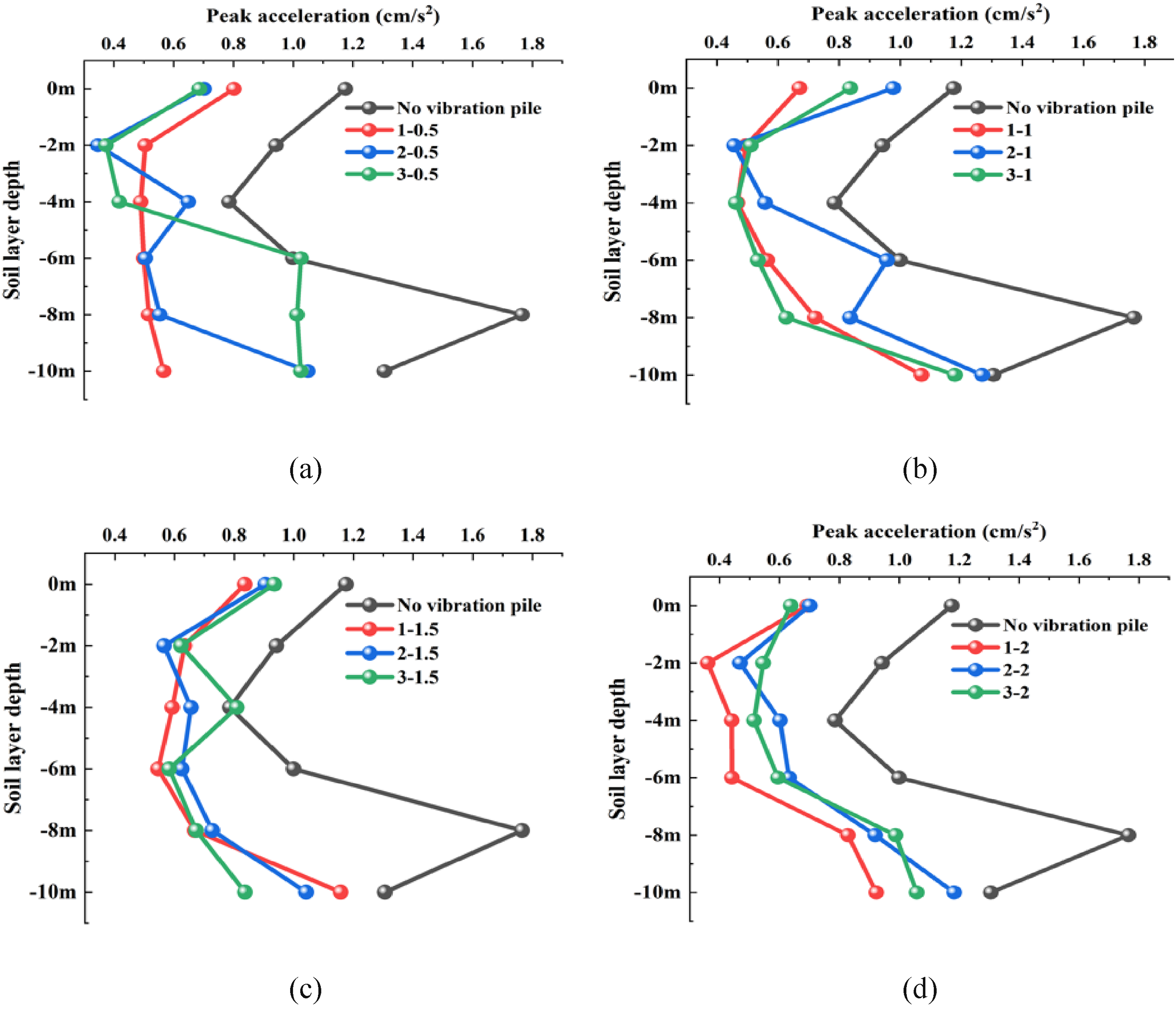
As shown in Figure 10(a), it is observed that when using a single row of piles and the soil depth ranges from 0 to 6 m, the peak acceleration is minimized with a pile spacing of 2r. Conversely, for soil depths between 6 and 10 m, the peak acceleration is minimized with a pile spacing of 0.5r. Additionally, under the influence of a single row of isolation piles, the peak accelerations of soil at different depths are significantly lower than those without any isolation measures. Notably, at a soil depth of 10 m and a pile spacing of 0.5r, the peak acceleration is markedly lower than at other spacings, constituting only 43% of the peak acceleration without isolation.

Shows the curves of peak acceleration varying with depth under the influence of single-row piles, double-row piles, and triple-row piles. (a) Single row of piles. (b) Two row of piles. (a) Three row of piles.
As shown in Figure 10(b), the peak acceleration is minimized when using double-row piles with soil depths ranging from 0 to 2 m and 6 to 10 m, and the pile spacing is 0.5r. Additionally, except for the case where the isolation pile spacing is 1r and the soil depth is 6 m, which closely approaches the peak acceleration without isolation measures, all other isolation measures significantly reduce the peak acceleration. According to Figure 10(c), the peak acceleration is minimized when using triple-row piles with soil depths between 4 and 8 m and a pile spacing of 1r.
According to Figure 10, it is observed that the peak ground acceleration is generally lower when the spacing between the vibration isolation piles is 2r compared to other spacings. In the absence of vibration isolation piles, the peak acceleration in the soil is highest at a depth of 8 m and lowest at a depth of 4 m. Under the influence of either single-row or double-row piles, the peak acceleration is highest at a depth of 10 m and lowest at a depth of 2 m. When using double-row piles, it is recommended to adopt a spacing of 0.5r, as this spacing results in peak accelerations that are lower than those of other pile spacings, except for a peak velocity that is larger at a soil depth of 4 m.
As shown in Figure 11(a), the vibration isolation effect of the triple-row pile is significantly better than that of the single-row and double-row piles when the soil depth ranges from 0 to 4 m. However, when the soil depth exceeds 4 m, the vibration isolation effect of the single-row pile is superior to that of the double-row and triple-row piles. According to Figure 11(b), the vibration isolation effect of the triple-row pile is significantly better than that of the single-row and double-row piles when the soil depth ranges from 4 to 8 m. However, at the ground surface and a soil depth of 10 m, the vibration isolation effect of the single-row pile is superior to that of the double-row and triple-row piles. As indicated in Figure 11(c), the vibration isolation effect of single-row piles is significantly better than that of double-row and triple-row piles when the soil depth ranges from 4 to 8 m. Similarly, Figure 11(d) shows that the vibration isolation effect of single-row piles is also superior to double-row and triple-row piles across a soil depth range of 2 to 10 m. It can be concluded that, contrary to expectations, the vibration isolation effect of multi-row piles decreases as the spacing between piles increases, falling below that of single-row piles.
Shows the curves of peak acceleration varying with depth under the influence of different row numbers of vibration isolation piles. (a) The pile spacing is 0.5r. (b) The pile spacing is 1r. (c) The pile spacing is 1.5r. (d) The pile spacing is 2r.
According to Figure 11, when the spacing between piles is 0.5r, it is recommended to use single-row piles. This is because the peak accelerations at a soil depth of 10 m for double-row and triple-row piles are approximately 1.8 times greater than those of single-row piles. Moreover, the peak acceleration of triple-row piles at a soil depth of 6 m exceeds that of piles without vibration isolation. When the spacing between rows of piles is 1r, it is recommended to use a single row of piles, as the peak acceleration at any soil depth is smaller with a single row. When the spacing is 1.5r, either a single or two row of piles is suggested because the peak acceleration at a soil depth of 4 m with three rows of piles is greater than that without the effect of vibration isolation piles. When the spacing is 2r, a single row of piles is recommended, as the peak acceleration at any soil depth is smaller with a single row.
Peak velocity isolation effect analysis of vibration isolation piles in time domain
As indicated in Figure 12(a), the peak velocities of soil at various depths under the influence of single-row isolation piles are significantly lower than those without isolation measures. At a soil depth of 10 m, the peak velocity is notably lower when the pile spacing is 0.5r compared to other spacings, amounting to only 70% of the peak velocity without isolation. According to Figure 12(b), when double-row piles are employed and the soil depth ranges from 4 to 10 m, the peak velocity is minimized at a pile spacing of 1.5r. Additionally, except for the case where the isolation pile spacing is 1r, which shows an increase in peak velocities at the surface and at a soil depth of 6 m, all other isolation measures result in a significant reduction in peak velocities. As indicated in Figure 12(c), the peak velocity is minimized when using a three-row pile configuration with a soil depth of 4 to 8 m and a pile spacing of 1r. Additionally, an increase in peak velocity is observed at a soil depth of 6 m when the pile spacing is 0.5r and at the ground surface when the pile spacing is 1.5r.

Illustrates the variation of peak velocity with depth under the influence of single-row piles, double-row piles, and triple-row piles. (a) Single row of piles. (b) Two row of piles. (c) Three row of piles.
According to Figure 12, both double-row and triple-row piles achieve the minimum peak velocity at a pile spacing of 0.5r when the soil depth is 2 m. When using single-row piles, it is recommended to set the spacing between the piles at 0.5 times r, as this spacing results in the minimum peak velocity at a soil depth of 10 m, with little variation in peak velocity at other soil depths. For double-row piles, it is advised to use a spacing of 0.5 and 1.5 times r, as this ensures the minimum peak velocity for any soil depth. In the case of triple-row piles, a spacing of 1 times r is recommended, as it yields the minimum peak velocity when the soil depth ranges from 4 to 8 m.
Based on Figure 13(a), it is recommended to use a single row of piles when the spacing between piles is 0.5r, as the vibration isolation effect of a single row of piles is significantly better than that of double or triple rows when the soil depth ranges from 4 to 10 m. However, at a soil depth of 8 m, the vibration isolation effect of two rows of piles is superior to that of a single row. According to Figure 13(b), when the spacing between piles is 1r, it is advisable to use a single row of piles, as the vibration isolation effect of a single row is significantly better than that of double or triple rows at any soil depth. However, under the influence of double-row piles at the ground surface and a soil depth of 6 m, a phenomenon of vibration enhancement was observed. As indicated in Figure 13(c), it is recommended to use single-row piles when the spacing between piles is 1.5r. This is because the vibration isolation effect of single-row piles is significantly better than that of double-row and triple-row piles within a soil depth range of 2 to 6 m. According to Figure 13(d), when the pile spacing is 2r, single-row piles are also recommended, as their vibration isolation effect is significantly superior to that of double-row and triple-row piles within a soil depth range of 2 to 8 m. However, the vibration isolation performance of double-row and triple-row piles is superior to that of single-row piles when the soil depth is 2 m and 10 m.

Shows the curves of peak velocity varying with depth under the influence of different numbers of vibration isolation piles. (a) The pile spacing is 0.5r. (b) The pile spacing is 1r. (c) The pile spacing is 1.5r. (d) The pile spacing is 2r.
According to Figure 13, without considering the vibration impact at a soil depth of 2 m, single-row piles offer the best vibration isolation effect in terms of peak velocity in the time domain. When using double-row piles, the spacing between piles should avoid 1r. Double-row piles can also be employed for vibration isolation when the spacing is 1.5r, and their performance is better than single-row piles both at the ground surface and at the soil depth.
Peak displacement isolation effect analysis of vibration isolation piles in the time domain
As shown in Figure 14(a), the peak displacements of soil at different depths under the influence of single-row isolation piles are significantly smaller than those without isolation measures. Figure 14(b) indicates that when double-row piles are used with a spacing of 1r, an increase in vibration is observed within the soil depth range of 0 to 2 m, while peak displacements under other isolation measures are significantly reduced. Figure 14(c) reveals that when triple-row piles are employed, the peak displacements at the ground surface all exhibit an increase.
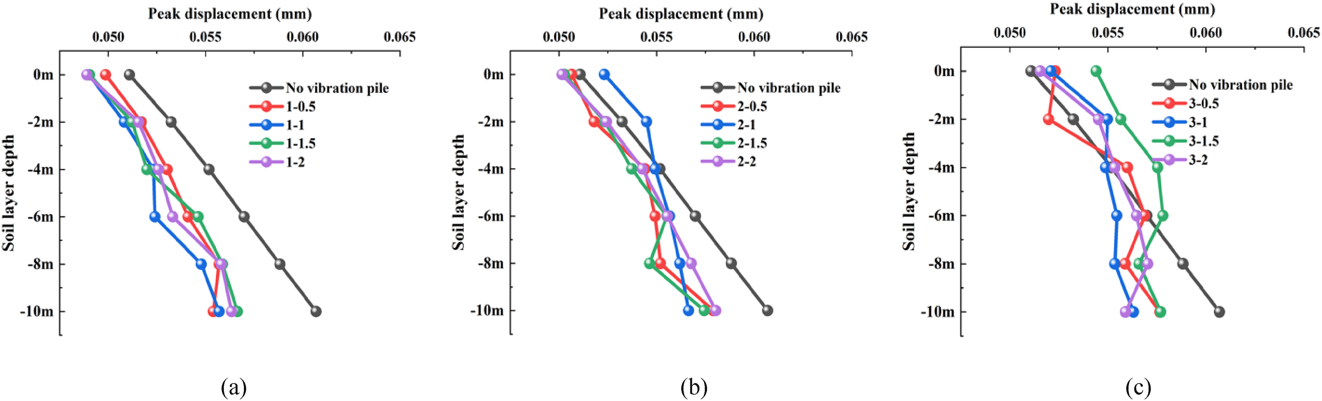
Shows the curves of peak displacement varying with depth under the influence of single-row piles, double-row piles, and triple-row piles. (a) Single row of piles. (b) Two row of piles. (c) Three row of piles.
According to Figure 14, at a soil depth of 2 m, both double-row and triple-row piles achieve their minimum peak displacements when the spacing between the rows is 0.5r. When using single-row piles, it is recommended to set the spacing between the piles at 1r, as this spacing results in relatively small peak displacements at any soil depth. For double-row piles, the recommended spacing is 1.5r, which ensures minimal peak displacements at any soil depth and avoids displacement amplification. However, when considering displacement isolation, especially for isolation at a distance of 10 m from the isolation piles, it is not advisable to use triple-row piles.
As indicated in Figure 15(a), the vibration isolation effect of a single row of piles is significantly better than that of double or triple rows when the spacing between piles is 0.5r. However, when the soil depth is 8 m, the vibration isolation effect of two rows of piles is superior to that of single rows. According to Figure 15(b), when the pile spacing is 1r, the vibration isolation effect of a single row of piles is significantly better than that of double or triple rows. As shown in Figure 15(c), when the pile spacing is 1.5r, the vibration isolation effect of a single row of piles is significantly better than that of double or triple rows. However, when the soil depth is 8 m, the vibration isolation effect of double-row piles is superior to that of single-row piles. As shown in Figure 15(d), when the spacing between piles is 2r, the vibration isolation effect of single-row piles is significantly better than that of double-row and triple-row piles. However, when the soil depth is 10 m, the vibration isolation effect of double-row piles is superior to that of single-row piles.

Shows the curves of peak displacement varying with depth under the influence of different row numbers of vibration isolation piles. (a) The pile spacing is 0.5r. (b) The pile spacing is 1r. (c) The pile spacing is 1.5r. (d) The pile spacing is 2r.
According to Figure 15, for peak displacement in the time domain, the vibration isolation effect of single-row piles is overall the best.
Discussion
Compared to recent studies, this research correlates pile spacing with the radius of the isolation piles. The primary focus of this study is on soil vibrations induced by train operations, rather than solely on surface vibrations. The study shows that the vibration isolation effectiveness of isolation piles varies with changes in pile spacing. Inappropriate pile spacing may even exacerbate soil vibrations. In terms of reducing vibration acceleration, single-row piles are more effective than double-row and triple-row piles in most cases, especially when the pile spacing is larger. For attenuating peak velocity, single-row piles consistently provide better vibration isolation at any pile spacing, while careful consideration of pile spacing is required for double-row and triple-row piles to avoid vibration amplification. Regarding peak displacement reduction, single-row piles are the most effective, particularly when the pile spacing is equal to the pile radius.
Due to the limitations of our study, we only investigated the impact of pile spacings of 0.5, 1, 1.5, and 2 times the pile radius on vibration. Future research could expand the range of pile spacings and explore the influence of varying front and rear pile spacings on vibration. Additionally, it is important to acknowledge that the current conclusions are applicable only to stratified soil with homogeneous composition within each layer. This limitation implies that the applicability of these findings may be affected in cases where the lateral geological structure is uneven.
Conclusions
This study first developed a numerical model that includes the train and track slab to address the wheel-rail interaction forces between the train and the rail. Subsequently, a finite element model with dynamic coupling of the track-tunnel-soil system was constructed, and the wheel-rail interaction forces were applied to it. The reliability of the model was validated by comparing the simulation results with measured data. The study then investigated the impact of isolation piles on soil vibrations under various influencing factors, leading to the following conclusions:
To reduce vibration acceleration in the soil within a depth range of 0 m to 2 m, the vibration isolation effectiveness decreases as pile spacing increases. When the pile spacing reaches 2 times the pile radius, single-row piles perform better. As the pile spacing increases beyond 1 time the pile radius, the vibration reduction effectiveness of double-row and triple-row piles in the 4 m to 8 m depth range becomes less effective than that of single-row piles. To attenuate peak acceleration in soils deeper than 6 m, the pile spacing should be set to 0.5 times the pile radius for single-row and double-row piles and to 1 time the pile radius for triple-row piles. At any pile spacing, single-row piles generally provide better vibration isolation in terms of peak velocity. When using double-row piles, the spacing should not be set to 1 time the pile radius, as this may lead to amplification of peak velocity. To reduce peak velocity in soils deeper than 2 m, the pile spacing should be set to 0.5 times the pile radius for single-row and double-row piles and to 1 time the pile radius for triple-row piles. To reduce peak soil displacement, single-row piles should be used, with the spacing set to 1 time the pile radius for optimal vibration isolation. When using double-row piles, the spacing should not be set to 1 time the pile radius, as this may result in displacement amplification.
Footnotes
Authors’ contribution
Shusen Cao and Dong Li contributed equally to this work and shared first authorship.
Data availability
The data that support the findings of this study are available from the corresponding author upon reasonable request.
Declaration of conflicting interests
The authors declared no potential conflicts of interest with respect to the research, authorship, and/or publication of this article.
Funding
The authors disclosed receipt of the following financial support for the research, authorship, and/or publication of this article: This work was supported by the Scientific Research Fund of the Institute of Engineering Mechanics, China Earthquake Administration (Grant No. 2021D32), the Fund of State Key Laboratory of Bridge Engineering Structural Dynamics (Grant No. 202104), and the Heilongjiang Province Ecological Environment Protection Research Project (Grant No. HST2023JC010).