
Abstract
In this research, we propose using active stabilizer bars to prevent rollover when steering. An intelligent control solution, the adaptive neuro-fuzzy inference system (ANFIS), is established in this article to control the performance of the active anti-roll systems. In contrast to the previously published studies, the intelligent algorithm designed in this research has many outstanding advantages, such as generating a large impact force, a fast response time, a small phase difference, and high convergence ability. The data used to train ANFIS are carefully selected and combined from the previous studies. The initial simulation observes that the roll angle decreases significantly from 8.15° to 6.87° when the ANFIS algorithm is applied to regulate the anti-roll bars. In contrast, the roll angles for the proportional-integral-derivative (PID) and passive (Mechanical) situations are respectively recorded at 7.08° and 7.80°. The reduction of the vertical force at wheels is also solved when the ANFIS algorithm is applied instead of other methods. This value increases sharply from 671.06 N (without bars) to 3030.40 N (ANFIS control), while it only reaches 2544.27 N (PID control) and 1428.83 N (mechanical bars), according to the research findings. If the vehicle does not have the anti-roll bars, a rollover occurs in the second case when the vehicle steers at v3 (80 km/h) and v4 (90 km/h). In contrast, the interaction between the wheels and the road is well maintained when the automobile is equipped with active bars controlled by the ANFIS solution. This is demonstrated by the minimum vertical force value in the rear wheel, which reaches 2687.33 and 2447.33 N, respectively, for the abovementioned conditions. In general, the vehicle's rolling stability can be well guaranteed in all moving situations when using the ANFIS controller for the anti-roll system in the vehicle.
Introduction
Literature review
Vehicle rollover accidents are relatively uncommon globally compared to other types of accidents. However, they are perilous and often have severe consequences (Figure 1). According to research by Xiong et al., rollover accidents comprised about 2% of total accidents but were responsible for nearly 35% of fatalities. 1 These statistics were cited in a 2011 report by the National Highway Traffic Safety Administration (NHTSA). Another study revealed that in 2017, over 30,000 individuals lost their lives in car crashes in the USA, with a significant portion involving rollovers. 2 Additionally, Alrejjal et al. 3 pointed out that over 30% of rollover accidents in the USA resulted in fatalities in 2017. Moreover, the incidence of rollover accidents is on the rise in other countries across the globe.
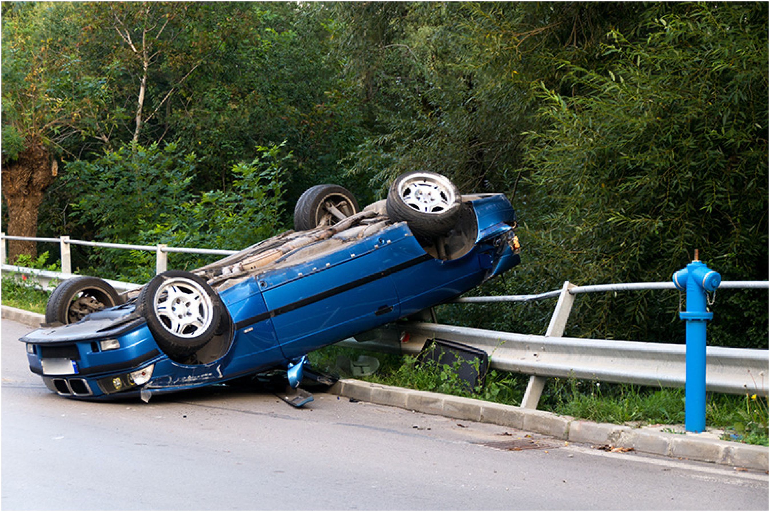
Rollover accident (source: https://nicoletlaw.com/blog/the-most-common-causes-of-rollover-accidents/).
Rollover accidents have various causes, which can be categorized into three groups. The first group pertains to driving conditions, while the second relates to vehicle construction. Additionally, the third cause encompasses driver's behavior and unexpected road situations, contributing to about 25% of all accidents, according to Cao et al. 2 Driving conditions, such as road geometry and surface roughness, can have a negative impact on steering, although this effect is usually insignificant.4,5 Jang et al. 6 mentioned that the slope of the main road in their study could be as steep as 50°, but such extreme conditions are rare for cars. Unstable situations may occur when vehicles travel on ramps, ditches (untripped), and curbs or soil (tripped), as stated by Han and Rho. 7 Additionally, Alrejjal and Ksaibati 8 highlighted the significant influence of environmental conditions on vehicle rollovers, a finding supported by subsequent research. 9 Moreover, studies revealed that rollover rates were higher for sport utility vehicles (SUVs) in adverse weather conditions, such as rain, wind, and temperature fluctuations.10,11 Alrejjal and Ksaibati also explored the impact of crosswinds on large trucks when navigating curves near mountainous areas. 12
The design of a vehicle significantly influences its susceptibility to rollovers. Imine et al. found that factors such as track width, center of gravity (CoG) height, and suspension system characteristics are closely linked to the occurrence of rollovers.
13
Research in
14
indicated that an increase in CoG height reduces the threshold for rollovers, while a wider track width decreases the likelihood of rollovers. However, the impact of CoG height was more substantial than the track width. Improper distribution of the vehicle's mass was also identified as contributing to rollovers. Wang and Chen's study
15
demonstrated that the CoG of the sprung mass changes as the roll angle increases or decreases, a finding also confirmed by Yang et al.
16
This change leads to a sudden increase in roll angle, which increases the risk of rollovers, as noted by Bencatel.
17
Adjusting the parameters related to a car's size and structure is a complex undertaking.

Driver's behavior significantly influences a vehicle's stability. Research has shown that when a car travels at high speed and the driver makes abrupt steering maneuvers, it can lead to rollover instability. This is due to the gradual increase in the vehicle's roll angle, which severely decreases the wheel's vertical force due to centrifugal force. When the vertical force approaches zero, the wheels can lose contact with the road surface, potentially causing a rollover. The relationship between mass, centrifugal acceleration, and centrifugal force is described by equation (1). Although the vehicle's mass remains constant, the position of its CoG changes with the roll angle. Centrifugal acceleration depends on the vehicle's velocity, steering angle, and steering acceleration. Therefore, quick changes in the steering angle during high-speed travel can significantly reduce the dynamic force on the wheels, leading to rolling instability that is hard to control.

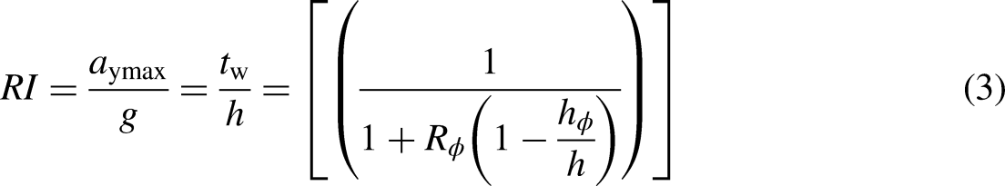
Various criteria assess vehicle rollovers, including reducing the limited roll angle or the wheel's vertical force.18,19 These two indicators are interrelated, but determining their exact dependencies can be challenging. Ataei et al.
20
introduced the static stability factor (SSF) for the car rolling model, which is determined by equation (2). They also proposed equation (3) in place of (2) to account for load changes caused by the suspension system, naming it the rollover index (RI).
20
However, Jin et al.
21
pointed out that this indicator is only suitable for static conditions and cannot be used for dynamic conditions. Consequently, an alternative index describing the change in the dynamic load of wheels, known as the load transfer ratio (LTR), should be utilized. LTR, illustrated in equation (4), ranges from −1 to +1. A zero value indicates a zero-roll angle and no change in load between wheels, while values of ±1 result in wheels separating from the road, causing rolling instability. The calculation of LTR incorporates lateral acceleration and roll angle, as shown in equation (5).21,22 However, it is essential to note that this traditional rollover indicator does not consider the influence of the unsprung mass. Jin et al.
22
introduced a new concept of the RI, accounting for the influence of other factors. This composite indicator, indicated by equation (6), integrates equations (4) and (5). Other representations of RI are also available and should be reviewed in23–25


Rollover instability is a critical issue that must be addressed promptly to enhance vehicle safety during maneuvers. Various methodologies have been developed to predict and mitigate the risk of rollovers, focusing on different aspects such as roll angle, vertical force, and wheel dynamics. Zhang et al. explored the use of contour lines of the lateral load transfer ratio (LTR) to predict rollover incidents. Their research, as illustrated in their publication, demonstrates a clear correlation between roll angle and roll rate across various velocities, offering significant insight into the dynamics of rollovers. 26 Furthering this investigation, Zhao et al. proposed a methodology based on estimating dynamic force changes at the wheels. Their findings, which considered sampling times of 0.05, 0.10, and 0.15 s, indicated a negligible difference between these conditions, suggesting a robust approach to predicting rollovers. 27 Nam et al. introduced an innovative approach utilizing tire force sensors to acquire rollover-related data swiftly. 28 Despite the potential for sensor failure due to external signal interference, they suggested that these challenges could be addressed by implementing an RI estimation algorithm that accommodates uncertainties, sensor faults, and unknown inputs. 29 Zhu et al. advanced the field by applying a vehicle rollover hazard warning algorithm founded on the principles of support vector machine (SVM) theory. 30 They defined a function R(x), dependent on the difference between the maximum LTR and a predefined threshold. This model flags rollover risk when R(x) dips equal to zero, establishing a quantitative basis for rollover assessment. 31 The application of recurrent neural network (RNN) algorithms for rollover prediction was also examined. 32 Despite notable inaccuracies in specific scenarios such as the fish-hook maneuver, this method, as discussed by Tota et al., showed promise in estimating LTR changes under varying motion conditions. 32 Surfacing a different approach, Chu et al. focused on the predictive potential of road surface data. 33 By employing cameras and sensors to compile road surface imagery, their system could estimate curve radius and, combined with data on vehicle speed, generate timely warnings for rollover risks.
Numerous studies have demonstrated that it is possible to anticipate rollovers by estimating road banking or vehicle roll angle in complex steering conditions. Guizhen et al. utilized a simplex dynamics algorithm for the 2 degrees of freedom (DOF) model to estimate road banking and the car's turning radius. 34 Jing et al. 35 employed an integrated control system to estimate output parameters such as yaw rate, roll angle, sideslip angle, and roll rate. According to Jing et al., the controller module was developed using the model predictive control (MPC) method. Jiang et al. introduced a new fusion algorithm in 36 which utilized optimal parameters to estimate the vehicle body roll angle, aiming to predict rollovers in advance. The results from 36 were validated through simulations and experiments. Boada et al. presented a new approach to estimating the vehicle roll angle, 37 using the H2 filter with uncertain parameters combined with the artificial neural network (ANN) algorithm. To simplify the problem, Boada et al. used a simple dynamic model described by approximate linear equations. This concept was further explored by Boada et al. in, 38 which included experiments and numerical simulations. Ye et al. introduced a new rollover prediction method based on the truck oscillation frequency. 39 Meanwhile, Park and Choi outlined an estimation of the change in the CoG height during steering. 40 Nguyen and Nguyen 41 illustrated the relationship between the car roll angle and various factors, such as the velocity of motion and the height of the CoG. The 4D graphs depicted in42,43 illustrated the relationship between these variables. Many other prediction methods should be consulted in.44–46
Implementing anti-roll methodologies is imperative to enhance vehicular safety at elevated velocities. According to Kongwat et al. in their work, 47 a body-optimized design strategy was deployed to mitigate the risk of vehicular rollovers during steering maneuvers. Concurrently, Seifi et al. 48 proposed optimizing passive suspension systems to bolster rolling stability, thereby marking a significant advancement in automotive engineering. In contemporary research, it is widely acknowledged that the stability against rollovers of vehicles can be considerably augmented through active control systems. In this context, Imine et al. 49 introduced an innovative approach by employing an active steering system governed by a sliding mode control (SMC) algorithm aimed at averting the rollover of heavy-duty vehicles. In a related vein, Tian et al. advanced this field by implementing the adaptive PID technique to manage the electric steering system, 50 highlighting the necessity for robust observers to enhance the operational efficacy of such systems. 51 Further contributions by Xiao et al. 52 demonstrated that active suspension systems could play a pivotal role in rollover prevention, underscoring the effectiveness of hydraulic actuators, known for generating substantial impact forces to ensure vehicular stability.53,54 Moreover, the stratagem of optimal torque distribution to the driving wheels has been acknowledged as a crucial factor in ensuring rollover mitigation, as evidenced by recent publications.55–57 Additionally, the application of active braking systems 58 and the synergistic use of active braking and steering mechanisms 59 have been identified as instrumental in elevating automotive safety standards. It is through the synthesis of such anti-roll control measures that a significant enhancement in vehicle safety can be achieved.60–65
Enhancing vehicular rolling stability during steering maneuvers is paramount for ensuring safety. Although various solutions have been proposed to address this issue, they only fulfill the rolling stability requirements to a certain extent. In complex scenarios, alternative, more efficacious solutions are necessitated. Dawei et al. 66 have underscored the efficacy of a stabilizer bar (also known as an anti-roll bar) in augmenting steering safety. Stabilizer bars are instrumental in diminishing the vehicular roll angle and in modulating dynamic forces acting upon the wheels. 67 Nguyen et al. 68 delineate two primary categorizations of stabilizer bars, namely passive (Mechanical) and active (electrical or hydraulic) systems. Passive stabilizer bars are used on most popular models, while active bars are often used on high-end cars. The architectural design of stabilizer bars typically adopts a symmetrical U-shape; however, this is not prescriptive, and their design can be varied to accommodate diverse applications. The fabrication of mechanical anti-roll bars frequently employs high-strength elastomeric steel. Kumar et al. 69 have noted utilizing specialized materials to fortify the anti-roll bar's robustness for heavy-duty trucks. These stabilizer bars are generally affixed to the unsprung mass of a vehicle, ensuring that the forces generated are directly transmitted to these components. Gao et al. 70 have provided a mathematical formulation for calculating the impact force generated by a passive anti-roll bar. This formulation posits that the force magnitude is contingent upon the displacement at the bar's attachment points and its inherent stiffness. Nevertheless, Gao et al. have predicated their analysis on the assumption that these forces predominantly influence the sprung mass. Conversely, a separate investigation by Nguyen articulates that the impact force of a passive anti-roll bar correlates with the displacement of the unsprung mass and bar dimensions. 71 Despite the mechanical anti-roll bar's affordability and compact design, its efficacy is limited. As with other anti-roll mechanisms, the passive stabilizer bar only partially addresses vehicle rollover phenomena. The deployment of active stabilizer bars presents a viable solution to this issue, offering enhanced performance in mitigating vehicular roll.
Active anti-roll bars are crucial for optimizing a vehicle's performance, particularly concerning safety and stability. Jeon et al. developed a noteworthy control algorithm for an electric stability bar designed for SUVs, 72 leveraging the SMC principle. Furthermore, Kong et al. proposed a hierarchical control strategy for electrical stabilizer bars in a three-tier model: upper, middle, and lower levels. 73 Despite the heightened sensitivity and ease of integrating electric stabilizer bars into modern vehicles, their cost-effectiveness and inability to generate a significant impact compared to hydraulic alternatives remains a challenge. Consequently, hydraulic stabilizer bars are the preferred choice among mid- to high-end vehicles, offering enhanced safety during abrupt steering maneuvers. The structure of a hydraulic anti-roll bar system was elucidated through a diagram in the study by Park et al., 74 highlighting the system's composition, including hydraulic cylinders, valves, a motor, and a pump. Nguyen proposed applying a traditional proportional-integral-derivative (PID) control algorithm for hydraulic stabilizer bars, characterized by its straightforward three-stage process correlating to the controller's functionalities. 75 In a divergent approach, 76 Muniandy et al. controlled hydraulic anti-roll bars using the PI-PD algorithm, with parameters tuned through a fuzzy logic technique, allowing for enhanced adaptability across varying rolling oscillation scenarios. This method was also performed by Dawei et al. 77 The fuzzy algorithm in76,77 had two inputs: the error signal and its derivative. The performance of this algorithm was proven with an experiment, according to Dawei et al. Vu et al. 78 designed a H∞/LPV controller for trucks’ hydraulic stabilizer bar system. The effect of oil leakage on hydraulic actuators was described Vu et al. 79 To overcome the constraints of fixed-parameter algorithms like PID, SMC, and H∞ (referenced in references,75,72 and, 79 respectively), dynamic fuzzy algorithms with numerous inputs were devised. Nguyen initially implemented a basic fuzzy algorithm with a singular input for the controller. 80 An advancement was made, as showcased in, 81 where the fuzzy controller was designed with dual inputs: car roll angle and unsprung mass displacement, a concept also mirrored in subsequent works.82,83 Significant variations in the design of fuzzy rules and membership functions across these studies81–83 resulted in distinct fuzzy surfaces, highlighting the diversity in approach. Building upon this, Nguyen 84 unveiled a novel fuzzy algorithm incorporating three inputs: unsprung mass displacement, resistant moment, and roll angle. Although the algorithm's configuration proposed in 85 was similar 84 based on three inputs, the values attributed to the membership functions and fuzzy rules differed. A paramount enhancement was introduced in 86 with the development of a comprehensive fuzzy controller including 125 cases across three membership functions, each defined by five levels: large positive (LP), large negative (LN), small positive (SP), small negative (SN), and neutral (NE). Simulation results from this study indicated a significant reduction in the roll angle under various rolling oscillation conditions, demonstrating the efficacy of the advanced fuzzy algorithm in enhancing vehicular safety.
Rollover control is a well-researched topic, with each study offering a unique approach. Various mechatronic systems, such as electric steering systems,49,50 active suspension systems,52–54 optimal moment distribution systems,55–57 and active braking systems, 58 have been proposed to limit vehicle rollovers. However, these solutions only partially resolve this issue. To ensure the roll stability of a car in extreme conditions, we recommend using active stabilizer bars. While recent publications on fuzzy control for anti-roll bars have shown promise, some drawbacks remain in the design of adaptive membership functions and fuzzy rules. The algorithms presented in80–86 only apply to several conditions. If we use the algorithm of 80 for conditions in 85 or apply the fuzzy controller of 82 for conditions in 84 and others, the performance of the system may decline. Fuzzy algorithms heavily depend on the design of membership functions and fuzzy rules, making it challenging to guarantee accuracy in all scenarios. Each control rule boasts advantages suitable for different car movement conditions. By combining these advantages, the controller's performance can be guaranteed in many cases.
New contributions
As mentioned above, applying fuzzy control to active stabilizer bars still faces two main disadvantages: (1) Each fuzzy algorithm, which is established based on certain fuzzy rules, is only suitable for some specific motion conditions. Applying a known technique to other cases may cause system performance degradation; (2) it is difficult to design optimal fuzzy rules and membership functions because they depend heavily on actual conditions and previous research experiences.
In this work, we propose to design an ANFIS self-learning algorithm to resolve the above issues. This algorithm provides two new contributions radically different from those of existing publications. First, the ANFIS algorithm designed in this study can take advantage of the outstanding advantages of the aforementioned fuzzy algorithms. At the same time, it can interpolate and make appropriate decisions in uncertain situations. Second, this combination can utilize previously verified experiences and fuzzy rules instead of proposing a new set of rules, which fails to guarantee accuracy. This combination helps expand the system's control range in many conditions instead of just certain ones. The ANFIS algorithm has been used on many mechatronic systems such as the suspension system, 87 steering system, 88 the power management system of an electric vehicle battery, 89 and others. However, it is rarely applied to control automotive stabilizer bar systems. Therefore, this may ensure the novelty and uniqueness of this article compared with other studies.
The content of this article is separated into four sections. A review of the literature and a description of the motivation for the study are provided in the first section (introduction). Mathematical models (including the vehicle dynamics model and control solution) are illustrated in the second section (mathematical model). The numerical simulation and calculation process are shown in the third section (result and discussion). The last section is the conclusion of the article.
Mathematical model
Vehicle dynamics model
In this study, we use a complex dynamics model to simulate the rolling oscillation of the car. This model combines a 3 DOFs nonlinear motion model and a 7 DOFs spatial oscillation model. This way, the factors related to the car's oscillation can be fully considered.
The spatial dynamics model (7 DOFs) is illustrated in Figure 2. The model has five masses, including one sprung mass ms and four unsprung masses mumn. The sprung mass ms can perform movements corresponding to 3 DOFs, including zs (vertical displacement), ϕ (roll angle), and θ (pitch angle). Meanwhile, unsprung masses can only perform one vertical displacement (zumn).
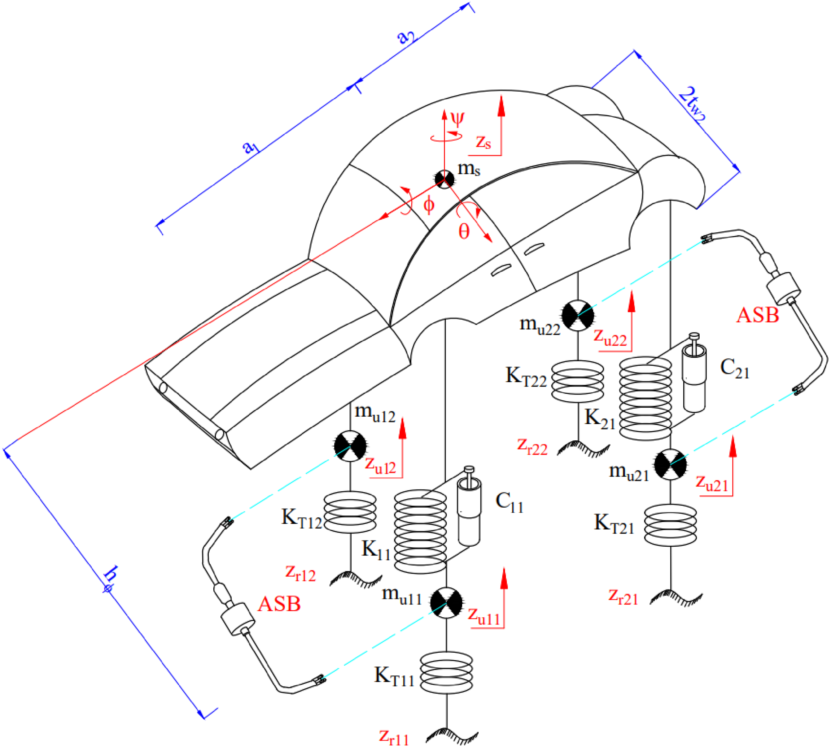
7 DOFs vehicle model.
Using the method of separating multi-body systems and d'Alembert's principle,
90
we get equations from (7) to (10).


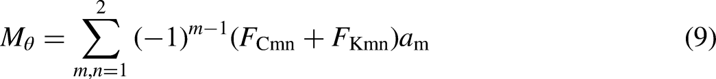


The moment of the stabilizer bar MSB is calculated by equation (19).

The moment balance equation on the shaft of the hydraulic actuator is shown as equation (20). The relationship between the motor shaft angle ϕm and the servo valve displacement inside the hydraulic actuator xsv is illustrated by equation (21).


To solve equations (20) and (21), we need to determine the spool valve displacement inside the cylinder. This displacement depends on the current supplied by the controller. Equation (22) gives information about the relationship between the control signal and the spool valve displacement.

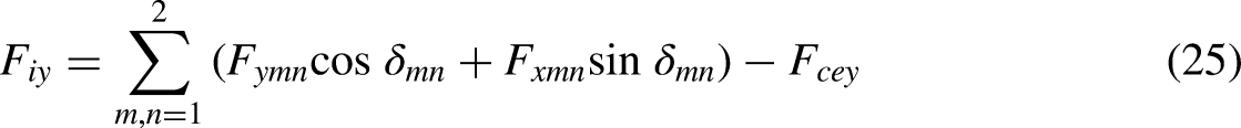
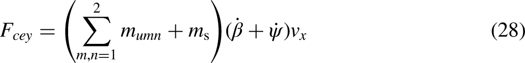
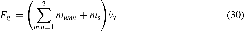
In equation (8), the value of the lateral acceleration ay (m/s2) is represented by the lateral velocity vy (m/s), the longitudinal velocity vx (m/s), the yaw angle ψ (rad), and the heading angle β (rad). This relationship is shown in equation (23).


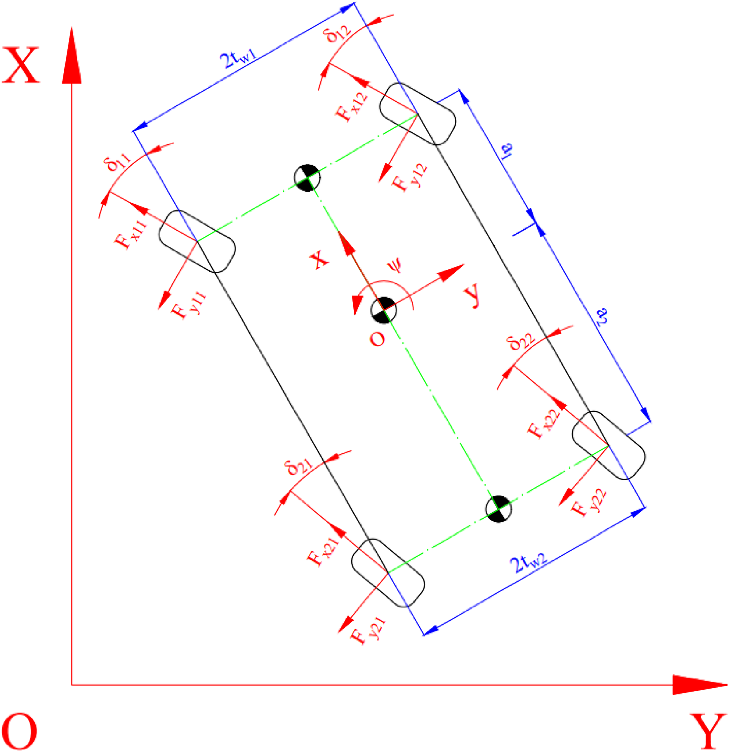
3 DOFs vehicle model.
The above equations are calculated through the following equations (27)–(31):


The longitudinal and lateral tire force values are calculated using the Pacejka tire model.
90
These values are functions of the vertical tire force Fz (N), slip angle α (rad), slip ratio s, and other factors. According to,
41
the longitudinal tire force value Fx is calculated according to equations from (32) to (36). Regarding Fy and Mz, the calculation process is similar (see
41
).


ANFIS model
Artificial neural networks and fuzzy theories have their disadvantages and advantages. Regarding fuzzy control, we can quickly build a system based on IF–THEN rules. However, the design and optimization of fuzzy logic systems are extremely difficult because they depend on the experience and knowledge of the scientists. In addition, we cannot determine the exact number and kind of appropriate membership functions and their combination. As for artificial neural networks, they can handle math problems at a fast pace. Additionally, they can learn through training. However, the tuning and description of neural networks are pretty complicated. Based on these characteristics, we propose using an algorithm that combines fuzzy theory and artificial neural networks called ANFIS.
Consider the fuzzy system represented by the following propositions:


According to Jing, the fuzzy system described from propositions (37) to (40) can be considered similar to a function y = f(x), which is continuous in any closed interval with a small error. 91 Using the typical membership functions from (41) to (45) (or others) and polynomials (46), we get output results of the fuzzy system according to weighted average (WTAVER) (47) or weighted sum (WTSUM) (48).
Triangular membership function (41):


Assume that we have a dataset {pm;tm}, where pm is the measured value from the input and tm is the value obtained from the system's output. The ultimate goal of the problem is to design a fuzzy system such that its output is similar to that of the system, i.e.


The gradient method is often used to achieve the minimization goal, as shown in equation (51).

We have (52), (53), and (54):


In this article, we use the ANFIS algorithm to design an intelligent controller for the anti-roll system. The total system structure is shown in Figure 4(a), whereas Figure 4(b) provides information about a self-learning algorithm diagram. This algorithm has two inputs: motion input (steering angle and vehicle speed) and body roll angle. The algorithm training process must follow the following steps: First, run simulations with the algorithms mentioned in.80–86 Then, change the vehicle speed and steering angle according to each algorithm. Second, the output results (control signals) corresponding to each simulation case are collected. Third, select and evaluate the obtained data. Eliminate inconsistent data and make necessary changes beforehand. Finally, provide a complete dataset for ANFIS training.

Control system diagram. (a) System control and (b) ANFIS diagram.
The gbellmf Membership Functions (MFs) are used for the ANFIS algorithm. According to Figure 5, each input has five membership functions. Therefore, the number of fuzzy rules used is 25, corresponding to 25 outputs of the membership function.

ANFIS model.
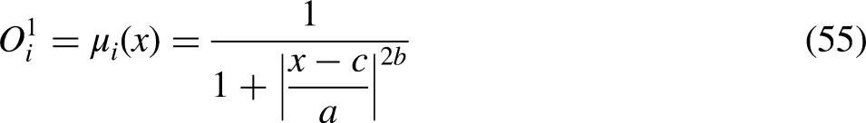
The ANFIS network consists of five layers. The first layer is Input MF, while the second and third layers are integrated into Rule. The fourth layer is Output MF, and Output is the last layer (Figure 5). The first layer includes nodes representing membership functions of fuzzy sets relating to input variables. The ith node is determined by equation (55).
The node's output in the second layer is the product of the inputs (56). The node's output in the third layer is normalized as shown in equation (57).


The dataset used for the ANFIS training process includes information regarding the two steering types, shown in Figure 6. The steering angle and acceleration are dynamically changed, but their shape remains. The car's speed varies over a wide range, from 50 to 100 km/h. Other values can be inferred from the ANFIS learning process.
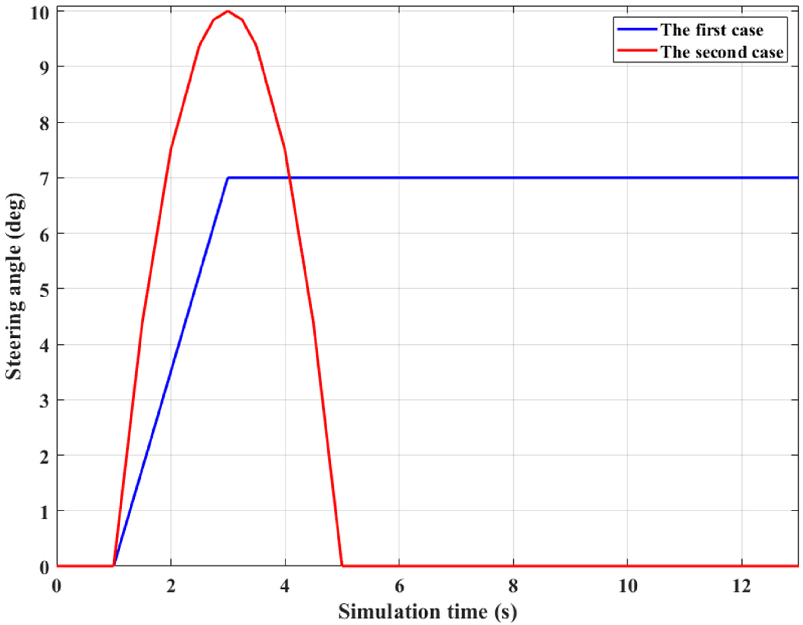
Steering angle.
Results and discussion
Condition
The car's rolling oscillation is evaluated through numerical simulation and calculation. The car's specifications are fixed and shown in Table 1. The inputs to the simulation include the travel velocity and the steering angle. At the same time, the outputs are the results related to the change in the vehicle roll angle and the attenuation of the vertical force.
Car specifications.

This research investigates the rolling oscillation in two cases, corresponding to two types of steering angles. According to Figure 6, the driver steers a J-turn in the first case. The steering angle rises from zero up to 7° and remains stable. This is a common type of steering angle often used in practice. In the following case, a sine steering angle is used. Its amplitude is more extensive than in the first case. The sine steering angle is used to investigate the convergence of the results after the steering angle reaches zero.
The car's speed is changed from v1 = 60 km/h to v4 = 90 km/h, corresponding to four levels. In each investigated condition, four situations are performed, including:
The 1st situation: the automobile has no stabilizer bar (None). The 2nd situation: the automobile has the passive stabilizer bar (Mechanical). The 3rd situation: the automobile has the active stabilizer bar controlled with the conventional algorithm (PID). The 4th situation: the automobile has the active stabilizer bar controlled with the intelligent algorithm (ANFIS).
The first case

The change of the vehicle roll angle when performing J-turn steering is depicted in Figure 7, corresponding to four speeds: v1 = 60 km/h (Figure 7(a)), v2 = 70 km/h (Figure 7(b)), v3 = 80 km/h (Figure 7(c)), and v4 = 90 km/h (Figure 7(d)). In general, their trend of change is similar. However, there is a significant variation in the roll angle value between different velocity levels.
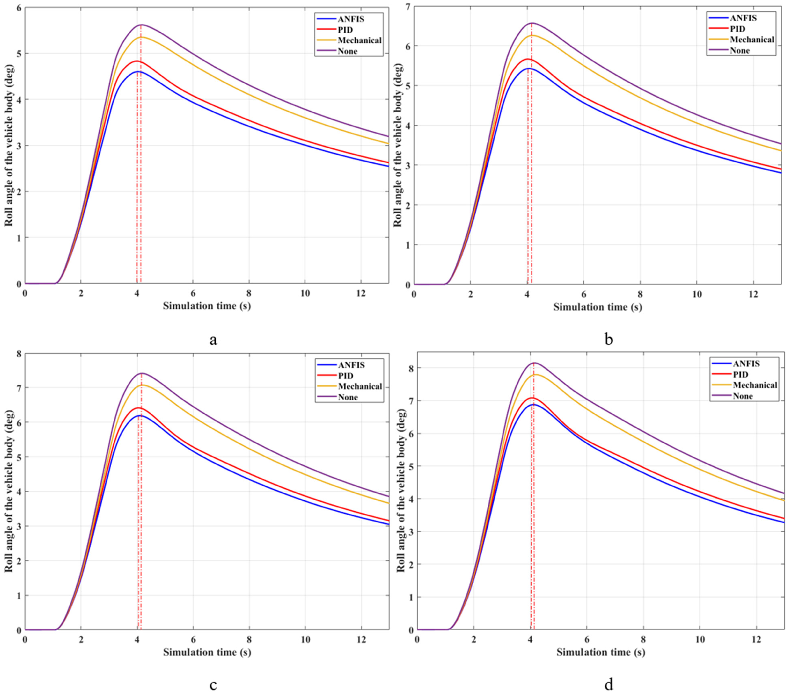
Roll angle. (a) v1 = 60 km/h; (b) v2 = 70 km/h; (c) v3 = 80km/h; (d) v4 = 90 km/h.
When the car steers at v1 = 60 km/h, the car roll angle rises after the first second (Figure 7(a)), and this value increases to a peak (after the fourth second). After that, it gradually decreases, although the steering angle is unchanged. The peak value of the vehicle roll angle when the automobile does not have stability bars is 5.61°. When cars use mechanical stabilizer bars, the roll angle slightly reduces compared to the above situation, reaching 5.35°. Using active stabilizer bars is a suitable solution to reduce the roll angle when steering. The simulation results illustrate that the maximum value of the body roll angle is only 4.83° and 4.60° when the active anti-roll bars are equipped on both axles, corresponding to the PID and ANFIS situations.
A small phase difference exists between the None, PID, and ANFIS situations. In terms of the None situation, the maximum value of the roll angle reaches later than when the steering angle reaches the maximum threshold. The inertia of the rolling motion causes this. When using control algorithms such as ANFIS or PID, the roll angle value can peak at an earlier phase, which is consistent with the steering angle. However, this phase difference is negligible, and the car's stability is unaffected.
Figure 8 depicts the fluctuation of vertical force at wheels. According to Figure 8(d), the difference in the vertical force between wheels is most remarkable when the car does not have the anti-roll bar. At the speed of v1 = 60 km/h, the value of the dynamics force at the wheel position (21) reduces to 1767.31 N. If the car is equipped with mechanical stability bars on the rear and front axles, the minimum vertical force value is raised to 2296.52 and 3506.79 N, respectively, for Fz11 and Fz21 (Figure 8(c)). Active stabilizer bars can generate large impact forces. Therefore, they reduce the difference in dynamic force between wheels. According to Figure 8(b), the minimum dynamics force value at the wheel position (21) is 3053.86 N, while at the wheel position (11), it is 4304.51 N. These values are obtained when cars use hydraulic anti-roll bars controlled by the PID controller. If this traditional controller is replaced with the ANFIS intelligent algorithm, the performance of the active stability bars will be further improved. The minimum vertical force at the wheel is only 3536.68 N when applying the ANFIS solution to the hydraulic anti-roll bars on the vehicle, as shown in Figure 8(a).

Vertical force (v1 = 60 km/h). (a) ANFIS; (b) PID; (c) Mechanical; (d) None.
When the car speed changes, the value of the vertical force and roll angle difference also change accordingly. At a velocity of v2, the increase in the roll angle is more considerable. Additionally, their peak values also increase compared to condition v1. Looking more closely at Figure 7(b), we can see that the maximum roll angle value may reach 6.57° if the vehicle does not use anti-roll bars. This figure is reduced by 0.34° when the mechanical stability bars are installed on the automobile. To help limit the vehicle roll angle, we should use the active stabilizer bar instead of the mechanical stabilizer bar. According to Figure 7(b), the peak roll angle is only 5.66° when applying the PID method to the active bar, while this figure is 5.43° once the ANFIS algorithm is applied to the system. A phase difference between situations still exists, but this is insignificant.
Figure 9 demonstrates the change in dynamic forces at wheels once the car steers a J-turn at v2 = 70 km/h. The dynamics force value at the wheel position (21) drops sharply to 1356.27 N if the automobile does not use the stability bar (Figure 9(d)). This figure is 1974.35 N for the car with passive stability bars on two axles (Figure 9(c)). This value can be increased to 2868.93 N when applying the PID solution to control active stabilizer bars (Figure 9(b)). The car's stability is always guaranteed once the anti-roll bars are directed with the ANFIS algorithm designed in this article. The minimum dynamics force is approximately 3356.67 N (Fz21) and 4615.70 N (Fz11), according to Figure 9(a).

Vertical force (v2 = 70 km/h). (a) ANFIS; (b) PID; (c) Mechanical; (d) None.
When the automobile steers at a more incredible speed (v3 = 80 km/h), the dynamics force and roll angle change are predicted to increase; this is a well-potential prediction, as seen from previous results.
The roll angle rises suddenly from zero to the top in a short period (Figure 7(c)), corresponding to the steering time. When vehicles use hydraulic anti-roll systems controlled by the ANFIS algorithm, the maximum value of the roll angle is only 6.19°. This figure increases slightly to 6.41° if the traditional PID controller is applied to the rolling stability system. The difference between these two situations is not significant. However, the roll angle can grow to 7.07° if the car has only mechanical stabilizer bars, while this value will reach 7.41° if the car does not have any anti-roll bars.
The larger roll angle also means that the difference in the vertical force is more considerable. According to Figure 10(a), the minimum vertical force value at the rear wheel position can be close to 3185.86 N when applying the ANFIS solution to control the stability bars. This number reduces to 2698.11 N if the ANFIS algorithm is replaced with the conventional PID algorithm (Figure 10(b)). The mechanical situation sees a dramatic decline in vertical force, reaching only 1685.08 N (Figure 10(c)), while the figure for the final situation does not exceed 1000 N (Figure 10(d)). The ANFIS algorithm shown in this article can help improve rolling safety when the automobile steers at extreme speed.

Vertical force (v3 = 80 km/h). (a) ANFIS; (b) PID; (c) Mechanical; (d) None.
At dangerous speeds (v4 = 90 km/h), dynamic force reduction is more evident. According to Figure 11(a), the dynamic force at the rear wheel reduces to 3030.40 N. This is a safe threshold that helps ensure the vehicle can move steadily without rolling over, even at increased travel speeds. This value will decrease to 2544.27 if we only use the conventional PID regulator to control the operation of the active bars, as shown in Figure 11(b). If vehicles only have mechanical anti-roll bars on the rear and front axles, they can help maintain a moderate level of wheel-to-road grip, which is illustrated by the value of the vertical force, Fz21 = 1428.83 N (Figure 11(c)). This figure is only half that of the ANFIS situation. Figure 11(d) shows the danger when a car steers at high speed without any stabilizer bars equipped. According to this result, the vertical force value at the rear wheel declines suddenly to 671.06 N. This shallow threshold indicates that the interaction between the wheel and the road is greatly reduced. A rollover may occur if the vehicle's speed or steering angle increases.

Vertical force (v4 = 90 km/h). (a) ANFIS; (b) PID; (c) Mechanical; (d) None.
The body roll angle increases rapidly in dangerous moving conditions (v4 = 90 km/h). According to Figure 7(d), the maximum car roll angle can be up to 8.15° when the automobile does not have anti-roll bars. The maximum values of the two mechanical and PID situations are 7.80° and 7.08°, respectively, while this number can decrease to 6.87° when applying the intelligent algorithm ANFIS for the anti-roll system.
Generally, the roll angle can be limited when the car uses stabilizer bars. In addition, the difference in vertical forces between wheels is improved if the car has active stability bars. The new algorithm ANFIS, shown in this article, can help enhance the automobile's stability when traveling at extreme speed.
The second case
In the next case, a different form of steering is used. This is a half sine with a larger amplitude than the first case (Figure 6).

Roll angle. (a) v1 = 60 km/h; (b) v2 = 70 km/h; (c) v3 = 80 km/h; (d) v4 = 90 km/h.
The PID control algorithm can ensure rolling stability to a certain extent. However, it causes rolling oscillation in the opposite direction after the steering angle returns to zero. According to Figure 12(a), the roll angle changes slightly to −0.13° and then returns to the equilibrium point. This is not the case with the other three situations. In the above situations, if the automobile uses hydraulic stability bars directed with the new ANFIS algorithm, the roll angle value will return to zero once the steering angle approaches zero. This is an advantage of the ANFIS algorithm compared to other solutions.
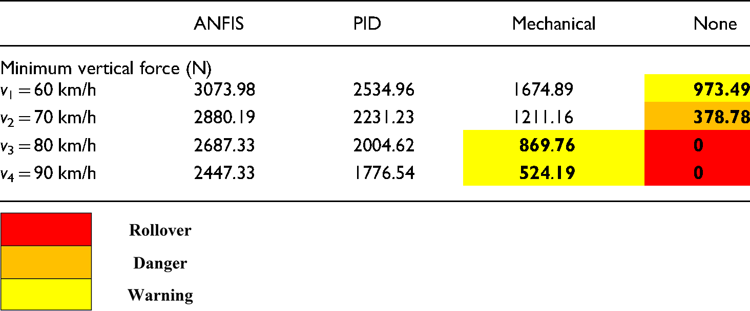
There is a big difference in the vertical force change when steering a sine instead of a J-turn. This is shown in Figure 13. At moderate speed (v1 = 60 km/h), the change in vertical force goes through only one phase if the automobile has no anti-roll bars or only mechanical stabilizer bars. However, this change has to undergo two phases once the vehicle uses anti-roll systems. The inertia of the rolling oscillation is the main cause of this. According to Figure 13(a), the minimum dynamics force is 3073.98 N when the vehicle has stability bars controlled by the new ANFIS algorithm. This shows that the wheel and road surface interaction is always guaranteed. If the car uses the traditional PID algorithm to control the anti-roll bars, the dynamics force value decreases slightly to only 2534.96 N (Figure 13(b)). The convergence of the dynamic forces at the wheel in both situations is good. They quickly return to the equilibrium point after the end of the steering process. However, the change in dynamic force increases dramatically once the automobile uses only two mechanical bars. According to Figure 13(c), the minimum dynamics force at the wheel position (21) is only 1674.89 N, even though the car only travels at v1 = 60 km/h (Figure 13(c)). If the vehicle has no stabilizer bars, this value drops below 1000 N (Figure 13(d)). Overall, if the new ANFIS algorithm controls the active stabilizer bars, it can increase the vertical force at the wheel three times compared to a car without any bars.

Vertical force (v1 = 60 km/h). (a) ANFIS; (b) PID; (c) Mechanical; (d) None.
In this moving condition, the car's stability is always guaranteed, even if the automobile does not have an anti-roll bar. However, if car speed continues to grow, rolling instability will occur.
After the steering process is finished, the roll angle value tends to zero. The traditional PID algorithm causes large inertia for the rolling oscillation. As a result, the car roll angle can reach as close as −0.2° before returning to zero. This only happens in PID and not in the other three situations (Figure 12(b)). When the new algorithm ANFIS is applied to anti-roll systems, the car roll angle returns to equilibrium after the steering is finished.
The change in dynamic force at wheels under this condition of motion (v2 = 70 km/h) is the same as in the previous condition (v1 = 60 km/h). However, this change is more potent, i.e. the dynamic force reduction is more extensive (Figure 14). When the ANFIS method is applied to the active anti-roll system, the dynamics force value is maintained around 2880.19 (N), as shown in Figure 14(a). When the traditional PID controller is used, the dynamic force value reduces by 648.96 N compared to ANFIS (Figure 14(b)). The convergence of values is still well guaranteed for both situations. However, the interaction between the road and wheels is severely degraded if the car has only mechanical stabilizer bars (or not). The dynamics force value at the rear wheel drops sharply to 1211.16 and 378.78 N, respectively, for Mechanical (Figure 14(c)) and None (Figure 14(d)) situations. This result indicates a dangerous warning when the automobile is not equipped with anti-roll bars. Once the vehicle's velocity increases, rollovers can occur immediately in the None situation. This is shown in the simulation results for v3 and v4 velocities.

Vertical force (v2 = 70 km/h). (a) ANFIS; (b) PID; (c) Mechanical; (d) None.
The roll angle value grows enormously when the automobile steers at v3 = 80 km/h. According to Figure 12(c), the roll angle rises to 9.39° when the automobile is not using the stability bar. Then, the rollover occurs for this situation at time t = 3.05 s. The vehicle roll angle can be increased beyond this value without causing a rollover if the vehicle uses anti-roll bars. In the Mechanical situation, the maximum roll angle may reach 9.37°, while the remaining values are 8.67° and 8.41°, respectively, corresponding to the PID and ANFIS situations. Similar to the two motion conditions (v1 and v2) mentioned above, the roll angle tends to change slightly in the opposite direction at the end of the steering process if we use the PID controller for the anti-roll system. However, it only reached −0.21° and quickly returned to the equilibrium value. For the situation where the ANFIS algorithm is used, this number should not exceed −0.03°.
At time t = 3.05 s, rollover occurs if the automobile does not have an anti-roll bar. This happens because the dynamic force at the rear wheel decreases suddenly to zero (Figure 15(d)). When steering at v3 = 80 km/h, cars can avoid rolling over once they have mechanical anti-roll bars. However, this is also dangerous, as shown in Figure 15(c). According to these results, the minimum dynamics force at the wheel is only 869.76 N, and it can continue to decrease (even to zero) if the travel speed or steering angle rises. This problem can be solved entirely using active stabilizer bars instead of mechanical ones. According to the findings illustrated in Figure 15(a) and (b), the interaction between the wheel and road is always guaranteed because the minimum dynamics force can be up to 2004.62 N (PID) and 2687.33 N (ANFIS). These safety thresholds ensure the vehicle can avoid rollover when steering at v3 = 80 km/h.
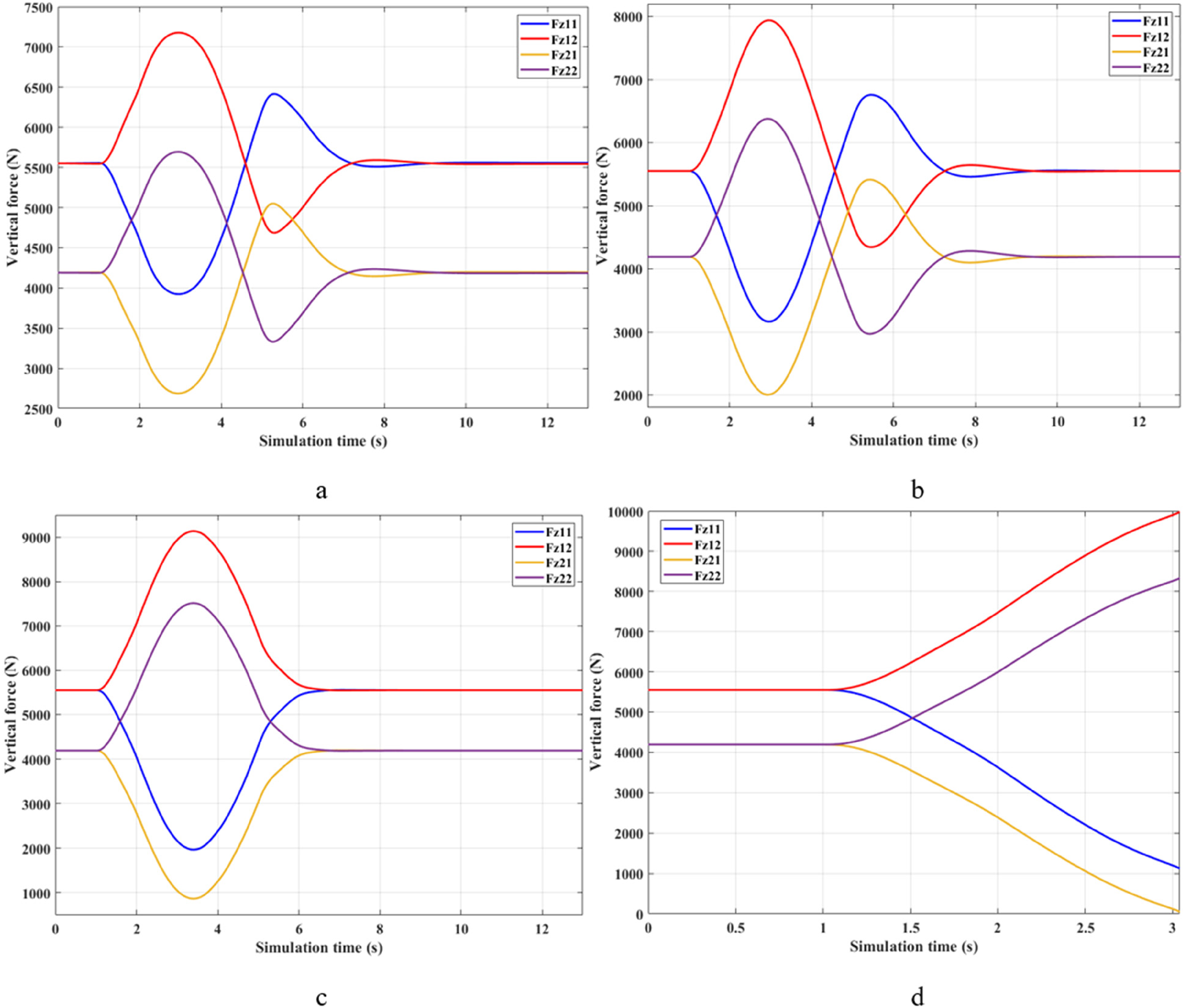
Vertical force (v3 = 80 km/h). (a) ANFIS; (b) PID; (c) Mechanical; (d) None.
In the final condition, the car speed can be up to 90 km/h. Rollovers are more likely to happen if the automobile does not have anti-roll systems. According to Figure 12(d), the roll angle value when the automobile does not have anti-roll bars is only up to 9.30° before the rollover occurs at time t = 2.81 s (Figure 16(d)). This indicates that the maximum roll angle is slightly declined because the rollover occurs earlier than in the motion condition v3. Meanwhile, the body roll angle can be up to 10.34° when the car only has mechanical stability bars. This is the result of reduced dynamic force at the wheel, which is illustrated in Figure 16(c). According to this result, the minimum dynamics force at the rear wheel is only about 500 N, so it quickly falls into rolling instability. Based on the above results, we can easily predict that if the car's speed increases by 10 km/h or the steering angle is increased by 1°, the car will roll over, although it is equipped with mechanical stabilizer bars.

Vertical force (v4 = 90 km/h). (a) ANFIS; (b) PID; (c) Mechanical; (d) None.
Active bars should replace passive stabilizer bars to ensure the automobile's safety when steering at a dangerous speed. If the PID controller is applied to the anti-roll system, the body roll angle will increase up to 9.57°, corresponding to the minimum dynamics force value of 1776.54 N (Figure 16(b)). Thanks to the novel algorithm ANFIS to control the active stability bars, the vertical force of the rear wheels can be raised to 2447.33 N, corresponding to a maximum roll angle of 9.34° (Figure 16(a)).
The active anti-roll system can help the vehicle maintain roll stability when steering at dangerous speeds. In addition, the intelligent control algorithm ANFIS, designed in this article, can control the operation of the anti-roll system better than the conventional control algorithm. This is proven through simulation results.
If the automobile's speed and steering angle continue to rise or the height of the CoG grows, rollover will occur immediately, although the vehicle has passive stabilizer bars. The PID control algorithm can only partially limit this phenomenon. To completely overcome this problem, we should apply the ANFIS control algorithm.
The numerical simulation results are listed in Tables 2 and 3 for the first case. For the second case, these data are summarized in Tables 4 and 5. The parameters of the PID controller in this study are selected by an optimal loop algorithm. Therefore, the efficiency of the PID algorithm is relatively high. According to the results in Tables 2 and 4, the roll angle value when using the ANFIS algorithm is about 0.3° lower than that of the PID algorithm. Besides, it is much lower than the Mechanical and None situation. This shows that the efficiency of the ANFIS controller is higher than that of the PID controller, even when the parameters of the PID controller are optimally selected. In addition, the difference in vertical forces is quite significant between ANFIS and PID (about 500 N). The results in Figures 8 to 11 show that the convergence of vertical forces obtained from ANFIS is more efficient than that from PID. Regarding roll angle, its convergence ability is more effective when applying the ANFIS algorithm (Figure 12). This helps reduce roll oscillations and improve the car's ride comfort.
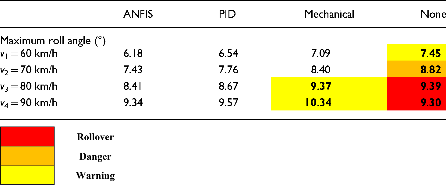
Maximum roll angle (the first case).

Minimum vertical force (the first case).

Maximum roll angle (the second case).
Minimum vertical force (the second case).
Simulation results for other scenarios are shown in the Appendix section. The steering angle of these scenarios is entirely different from the scenarios learned in80–86 (See Supplemental Figure 17). According to the simulation results, the performance of the PID controller is degraded in the third case. Therefore, the results provided by the PID situation are inferior to the Mechanical situation (See Supplemental Figures 18 to 22). In the fourth case, the vehicle's roll angle when using the PID controller increases in the final phase of the oscillation (See Supplemental Figures 17 to 27). In contrast, the car's roll stability is always guaranteed when the ANFIS algorithm controls the active anti-roll system. This is demonstrated in various scenarios (four steering angles and eight speed values).
The algorithm presented in this study demonstrates superior performance in ensuring stability and adaptation to changing factors, such as vehicle speed and steering angle, compared to the fuzzy techniques discussed in.80–86 External simulations have indicated that the algorithm proposed in 80 exhibits performance degradation when applied to the conditions outlined in. 85 Likewise, the system's reliability is not assured when employing the technique mentioned in 82 in the scenario depicted in. 84 However, the approach employed in this study effectively addresses these issues. Furthermore, the stability of the ANFIS algorithm is ensured even when the system encounters untrained cases (see the Appendix section). Compared with, 94 the algorithm proposed in this work is designed with a different structure with different inputs and rules. As a result, it can provide more adaptation to many moving conditions.
The algorithm proposed in this work offers two key advantages. Firstly, it applies to a wide range of motion conditions rather than being limited to specific ones. Secondly, it incorporates the benefits of established fuzzy techniques that rely on selective training. However, there are still some challenges in the algorithm design. Initially, gathering substantial data for the training process is essential. This data is obtained through multiple simulations using validated algorithms under various conditions and must be carefully scrutinized to remove irrelevant information. In addition, appropriate training rules need to be selected, including the number of layers, calculation rules, membership functions, and epochs. If the training rules are poorly chosen, the process will soon end with inaccurate results. On the contrary, this process will take longer if the algorithm is established based on many strict conditions.
Conclusion
A rollover can occur when the driver quickly turns at a dangerous speed. The leading cause is the quick decrease in dynamic force at the wheel, which cancels the interaction between the wheel and the road. The roll angle can increase to a critical value before the rollover occurs, corresponding to the moment when the wheel is separated from the road (the value of the vertical force approaches zero).
This research proposes using the intelligent control algorithm ANFIS to control the hydraulic stability bars. This algorithm is trained using a significant amount of data gathered from the previous studies. In addition, these data are aggregated from multiple control algorithms that correspond to specific motion conditions rather than a single algorithm. The complex dynamics model is used to simulate the car rollover.
The simulation result shows that the value of the roll angle decreases when the automobile has the stabilizer bar. In addition, the active anti-roll bar can decline the roll angle more than the mechanical stabilizer bar. This also means that the active stabilizer bars can help limit the reduction of vertical force at the wheel when steering at high speeds. According to the research findings, the ANFIS algorithm helps ensure rolling stability in all surveyed cases, even when the car steers at high speed. Suppose the speed of movement and steering angle continue to increase. In that case, the rollover can still be well prevented if we apply the intelligent algorithm ANFIS to the hydraulic anti-roll system.
Future works
The proposed algorithm has effectively addressed two significant issues but encounters challenges in real-time applications. First, the calculation process does not factor in the system delay. Second, the training rules are primarily based on experience rather than optimal calculation, potentially impacting the test results under harsh conditions. Additionally, the algorithm has yet to consider the effects of disturbances and environmental conditions fully. Finally, conducting experiments is essential to demonstrate the algorithm's performance. These issues are expected to be addressed in future work.
Several related experiments can be conducted to validate the system's quality in the future. These experiments can follow the outlined steps:
Install active stabilizer bars on a fully equipped vehicle system model, including suspension, brakes, steering, wheels, and other necessary components. Place sensors in appropriate locations. Update the proposed algorithm for a real-time device (MicroAutobox II). Establish the required initial conditions. Perform steering maneuvers at various speeds. Then, measure and compare the output signals from the sensors with the simulation results. It is crucial to ensure that the simulation and experimental conditions are equivalent.
Supplemental Material
sj-docx-1-sci-10.1177_00368504241274976 - Supplemental material for Adaptive neuro-fuzzy inference control for active stabilizer bars based on multiple data sources
Supplemental material, sj-docx-1-sci-10.1177_00368504241274976 for Adaptive neuro-fuzzy inference control for active stabilizer bars based on multiple data sources by Tuan Anh Nguyen in Science Progress
Footnotes
Author contributions
All content in this article was prepared by Tuan Anh Nguyen.
Data availability
The data used to support the findings of this study are available from the corresponding author upon request.
Declaration of conflicting interests
The author declared no potential conflicts of interest with respect to the research, authorship, and/or publication of this article.
Funding
The author received no financial support for the research, authorship, and/or publication of this article.
Supplemental material
Supplemental material for this article is available online
References
Supplementary Material
Please find the following supplemental material available below.
For Open Access articles published under a Creative Commons License, all supplemental material carries the same license as the article it is associated with.
For non-Open Access articles published, all supplemental material carries a non-exclusive license, and permission requests for re-use of supplemental material or any part of supplemental material shall be sent directly to the copyright owner as specified in the copyright notice associated with the article.