
Abstract
The current path tracking control method is usually based on the steering wheel angle loop, which often makes the driver lose control of the automatic driving control loop. In order to involve the driver in the automatic driving control loop, and to solve the vehicle path tracking control problem with system robustness and model uncertainty, this paper puts forward a steering torque control method based on model predictive control algorithm. Based on the vehicle model, this method introduces the steering system model and the steering resistance torque model, and calculates the optimal control torque of the vehicle through the real-time vehicle status, so as to make up for the model mismatch, interference and other uncertainties, and ensure the real-time participation of the driver in the automatic driving control loop. To combine the nonlinear vehicle dynamics model with the steering column model, and to take the vehicle state parameters as the feedback variables of the model predictive controller model, then input the solution of the steering superposition control rate into the vehicle model, the design of the steering controller is realized. Finally, to carry out the simulation of lane keeping based on CarSim software and Simulink control model, and the hardware in-the-loop test on the hardware in-the-loop experimental platform of CarSim/LabVIEW-RT. The simulation and test results indicate that the designed torque loop path tracking control method based on model predictive control can help the driver track the target path better.
Introduction
While the vehicle is moving, the technology that the driver completely disengages from the vehicle control system is called driverless technology. With the development of modern automobile industry, driverless vehicle technology has gradually become a hot topic for scholars at home and abroad.1–3 At present, driverless vehicles are mainly controlled by the steering wheel corner ring. In the process of vehicle operation, the driver is often disengaged from the automatic driving control loop, which is easy to cause adverse effects such as ‘situation mode’ reduction.4,5 In order to solve many problems faced by driverless, scholars at home and abroad put forward the concept of ‘human-computer co driving’ intelligent vehicle. It refers to the driving mode in which the driver and intelligent system share vehicle control and cooperate to complete vehicle control. At present, human-computer co driving has attracted the attention of many scholars and will become a new development direction of intelligent driving.6–9
Many scholars have conducted a lot of researches on the lateral control of driverless vehicles, and have achieved good control results. In order to verify the path tracking effect and motion stability of the vehicle in the unknown environment, Pan Zhao et al. used the adaptive PID control algorithm to represent the path tracking problem in the form of state control network, and achieved good results in vehicle control flexibility 10 ; Riccardo Marino et al. 11 proposed a nested PID steering control algorithm based on visual driverless vehicles, conducted path tracking experiments on roads with uncertain curvature, and achieved good path tracking results; Gaining Han et al. 12 established a neural network PID controller based on vehicle model and steering system model, so as to track the lateral path of vehicles .The simulation results show that the method has high real-time performance. Al mayyahi et al. 13 proposed a fractional order PID(FOPID) control algorithm for the path tracking of driverless vehicles. The controller shows good performance in minimum path tracking error and compensation path tracking.
However, in the research of path tracking based on PID control, its parameter adjustment is often based on experience and lack of self adaptability. Considering the influence of parameter uncertainty, Chuan Hu et al. 14 proposed an adaptive Lubang linear quadratic regulator, and made simulation experiments to verify the control effect of the controller. Nematollah Tavan et al. 15 put forward the optimal Linear–quadratic regulator (LQR) to calculate the optimal steering angle and torque of the vehicle, improved the stability of the vehicle in the expected torque and the ability of path tracking. Peng hang et al. 16 designed linear quadratic (LQR) optimal controller for four-wheel independent steering vehicle, and verified the control effect of the controller through simulation; Jiang Libiao et al. 17 proposed a non-time reference terminal synovium path tracking control algorithm based on approach rate, and verified the rationality of the planned path and the effect of the path tracking controller through the co-simulation of Simulink and Carsim. Li Hongzhi of Tsinghua University et al. put forward an adaptive control algorithm based on preview time in reference, 18 which can complete driving operation under various complex conditions; in order to improve the accuracy of vehicle path tracking under emergency obstacle avoidance conditions. In reference, 19 a path tracking control strategy based on the combined control algorithm is proposed. The algorithm establishes a control strategy based on the yaw rate stability control algorithm and combined with the preview error model, which effectively improves the path tracking accuracy of the vehicle under the condition of emergency obstacle avoidance.
The above research can significantly improve the vehicle path tracking. However, it can not effectively solve the problem of anti-interference. In order to improve the anti-interference ability of the controller, many scholars apply Lubang control theory to path tracking. Chuanhu et al. 20 proposed a path tracking output feedback control strategy for Lubang driverless vehicles. The algorithm has strong robustness to parameter uncertainty and external interference, and the path tracking effect is good through simulation. Wu Jian et al. 21 designed a generalized internal model robust controller for the contradiction between the performance and stability of the controller. By compensating the uncertainty of vehicle parameters, the performance and robustness of the controller were improved; Xie Youhao et al. 22 designed a robust lateral control based on μ synthesis method for human-computer co driving of intelligent vehicles, which improved the interference suppression ability for both side wind and driver’s misoperation; Chuan Hu et al. 23 proposed a Lubang control algorithm based on linear matrix inequality (LMI). The algorithm can maintain the path tracking ability and system stability under uncertain external interference. In order to solve the problem of constraint control and improve the robustness of the system, many scholars apply the method of model predictive control to the research of path tracking control. Model predictive control (MPC) is an effective control strategy for constrained optimal control. For its ability in dealing with the nonlinear, uncertainty and constraint problems of vehicle dynamic model, many researches have adopted MPC control method to solve the control problem of path tracking.24,25 Lei Li et al. 26 established the optimal model predictive controller by dynamically searching the optimal linear model parameters when the model was matched, and designed a simulation experiment to verify the path tracking performance of the driverless vehicle.
All the above studies can solve the problem of vehicle path tracking control, but the control mode is to control the steering wheel angle as a single input, which undoubtedly requires a very high precision steering wheel angle; in the control process, the steering wheel is locked, resulting in the driver being unable to participate in the driverless control loop, which increases the driver’s psychological burden in emergencies. In order to solve this problem, reference 27 proposes a steering assist system control strategy based on torque control, which improves the yaw rate tracking effect and stability of the vehicle. This algorithm not only takes the vehicle and actuator constraints into consideration, but also the specific constraints related to the interaction and cooperation between the driver and the actuator. However, this kind of input method that takes the driver’s hand torque as interference will make the output torque of the motor much higher than that of the driver’s hand, so as to reduce the influence of the driver’s operation stability; In reference, 28 a torque distribution strategy based on hierarchical structure is proposed to control the operation stability of the vehicle, and a relatively perfect control model is built, which achieves good control effect in the simulation. However, it is almost impossible to make the connection between hierarchical structure perfect, the actual vehicle verification does not achieve good control effect. These control algorithms can achieve good path tracking effect.
The above path tracking control method has made great progress. However, due to the gap between the steering control model and the actual steering system, some studies fail to ensure the real-time participation of drivers in the driverless control loop and lack of experiments to verify the effectiveness of the algorithm. In this paper, a steering torque control strategy based on MPC control algorithm is designed. The motor torque in the steering system is used as the control input to achieve interpersonal collaborative control, which has a faster response speed. It can solve the problem of external constraints and model uncertainty 29 ; while ensuring that the driver participates in the driverless driving control loop in real time. This control method adopts receding horizon optimization to predict the system state of a period of time in the future and obtain the control input that minimizes the objective function. As an effective control method, MPC control solve the constraints problem by converting the constraints into the quadratic programming and nonlinear programming. In this way, the external interference or the error information of the model in the measured value is effectively used to promote the stability of the system performance. In this paper, based on the simulation of the algorithm, an active steering test-bed based on LabVIEW RT is designed and tested. The results show that the model predictive side controller has faster response speed and better control effect. Especially in the actual use process, it can improve the robustness of the system, has a very good suppression effect on external constraints, noise interference, and can guarantee the vehicle path tracking performance. The parameter variables used in this article are as shown in Table 1
Parameter variables.

Model predictive control strategy
The overall control strategy of MPC is shown in Figure 1. It includes two degree of freedom module, tire model, steering system model, controller and other modules. The model predictive controller directly gives the steering superimposed torque, which is transformed into the target steering angle by the steering system module to directly act on the vehicle and realize the lateral stability control of the vehicle.

The overall control strategy of MPC.
Vehicle control model
The vehicle two-degree-of-freedom model studied in this paper is shown in Figure 2. 30

Two-degree-of-freedom vehicle model.
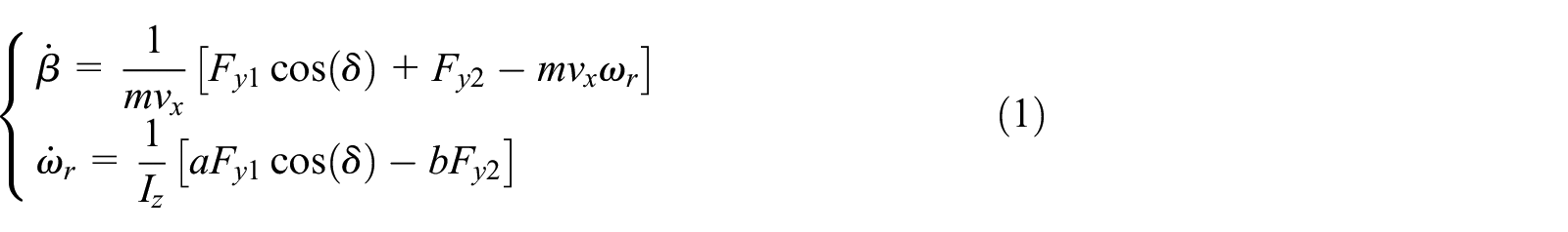
The vehicle dynamic equation is as follows:
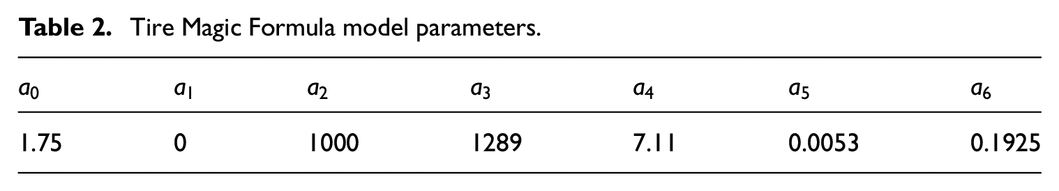
In order to better describe the control stability of vehicle tire in nonlinear region, this paper adopts the magic tire model. 31

Where

Where:

Where,
Tire Magic Formula model parameters.
The wheel side Angle of the vehicle is obtained by measuring parameters and estimating.

Where
Assuming that the current vehicle condition is

Substituting equation (5) into equation (1) to obtain the linearized state space equation of the system as follows:

The model is of second order with state vector as
where the coefficient matrix
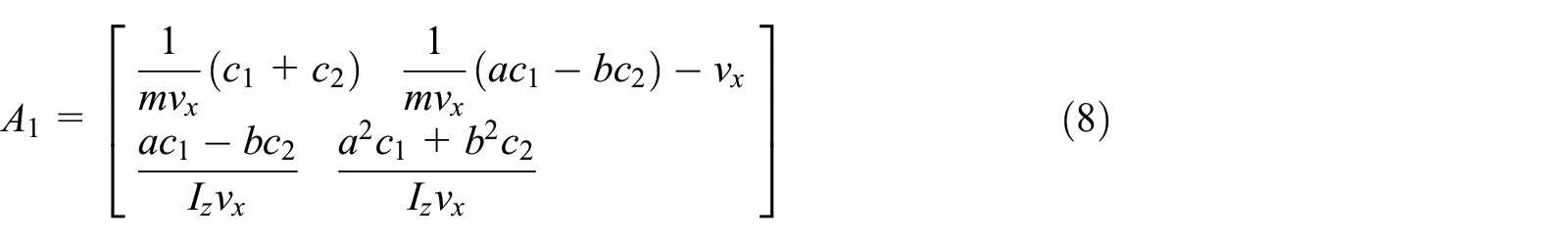

Where
Steering system dynamatics model
For the convenience of research, the front wheel of the steering system and the steering shaft are simplified appropriately in this paper, and the dynamic relationship between the equivalence of each force to the steering shaft is emphatically studied. On the basis of ensuring the reliability of the model, the relationship between each input and output variable is established. The steering system model is shown in Figure 3.

Steering system dynamatics model.
In order to better integrate steering dynamics into the vehicle dynamics system, the same force is applied to the kingpin. According to the characteristics of the steering system, it can be obtained as follows:

Where


According to equation (10), by taking

Where:


According to the above two sections, the steering system model and the dynamics model can be combined to obtain a fourth-order combined dynamics model, which can be expressed as:

Where:


The above combination releases the steering wheel control Angle as a state variable through the control model, and converts the control variable into torque control to control the vehicle tracking ideal path, and calculates the interference through the dynamic equation
Model predictive controller design
In the practical application, the controller runs at a certain time intervals, so the continuous-time system model can be transformed into a discrete-time system model in order to establish the controller. The discrete equation can be obtained by discretization of the equation (16):

Where:

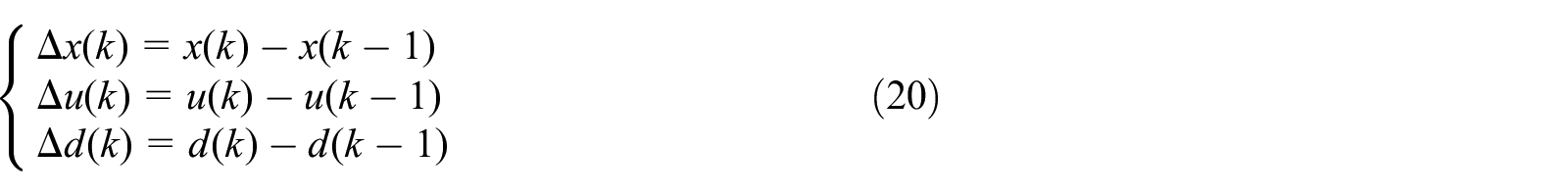
In order to introduce the integrals to reduce or eliminate the static errors, equation (17) is rewritten as an increment. The predictive function is described as:

Where:
Let the predictive horizon and control horizon be
(1) The amount of system control outside the control time domain remains unchanged, namely:

(2) The detectable interference remains unchanged after the current control moment, namely:

Therefore, the predictive output system of the system can be expressed as:


The
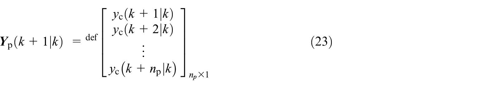

According to equation (19), the predicted outputs of the system in the next

Where:


Longitudinal acceleration and lateral acceleration are limited by the ground adhesion, and have the following relationships:

Where,

In this paper, the solver will dynamically adjust the constraint condition according to the solution of each control cycle. As shown in equation (30):

Where
Therefore, the performance indexes of the system can be obtained as follows:

Where
The reference output can be expressed as:


The weighted matrix of output and control input is as follows:

The incremental form of constraint sequence is:

Finally, the output of the optimal control torque is obtained as follows:

Simulation analysis
In order to better verify the control performance of MPC, this paper designs the simulation experiment of path tracking. The optimal control rate solved by the Simulink control model is used as the control input of CarSim, the friction coefficient of the road is set to 1, the double moving line is selected as the target path, and the speed is set to 50 km/h for simulation verification. In order to better illustrate the control effect of the model predictive algorithm, the simulation results are compared with the proportional integral derivative (PID) control scheme. The PID control parameter are
Figure 4 shows the path tracking comparison effect of the two control methods. It can be seen from the figure that both methods can effectively track the target path, but the PID method overshoot about 4% in6-8s due to energy accumulation, while the vehicle using the model predictive control algorithm has no obvious jitter, and the overall path tracking effect is better.

Lateral displacement.
Figure 5 is the comparison diagram of steering wheel angle and steering wheel torque under the control of two algorithms. From Figure (a), it can be concluded that the steering wheel angle amplitude of the model predictive control algorithm is 47deg, which is obviously smaller than the steering wheel angle of the PID control algorithm. From Figure (b), it can be seen that the equivalent torque input amplitude on the steering column is 8nm, which is obviously smaller than the vehicle controlled by the PID control algorithm, and the equivalent torque input fluctuation is greater than PID control algorithm, which shows that the energy consumption of rolling time-domain control algorithm is significantly lower than PID control, and can make the vehicle control more stable by constantly modifying the vehicle trajectory.

The steering wheel angle and steering column input torque: (a) Steering Angle and (b) Steering wheel torque.
The comparison of vehicle yaw rate under the two control conditions is shown in Figure 6. It can be concluded from the figure that compared with PID control, the vehicle response speed of model predictive control is faster, the vehicle is in a stable state for a long time, the rate of change of yaw rate is low, and the vehicle operation performance is better. The comparison of the sideslip angle and the lateral acceleration of the vehicle is shown in Figures 7 and 8 respectively.

Side slip angle.

Yaw velocity.
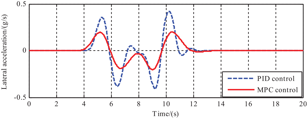
Lateral acceleration.
HIL implementation
In this section, the controller is embedded in the HIL (hardware-in-loop) platform to verify the real control effect of the controller. 33 In HIL, although vehicle simulation software or commercial vehicle simulation software is used to replace the real control vehicle, the actuator and control system are real vehicle actuators, so they are widely used in enterprises and universities in vehicle path tracking control and driverless driving control logic verification. The hardware in the loop test-bed used in this paper is shown in Figure 9. The test-bed includes the steering system with C-EPS, the servo motor used for resistance loading, the hydraulic braking system, the PXI real-time system used to embed the whole vehicle model and the environment model, and the d-SPACEof the real vehicle controller.
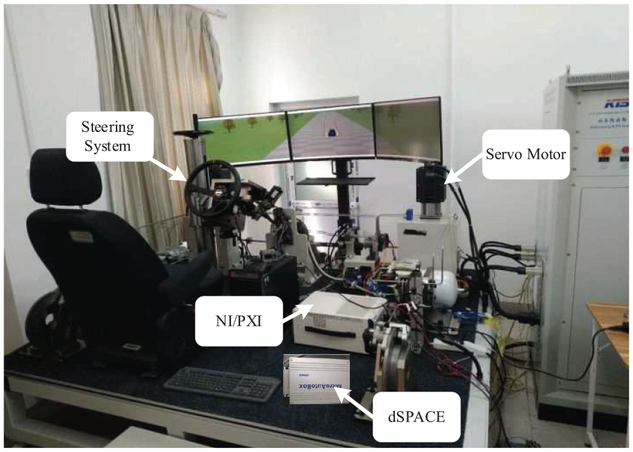
The hardware in the loop test-bed.
This steering system has the functions of torque control and electric power steering. In order to better verify the control algorithm of steering torque superposition, a torque loop based on d-SPACE is built before the verification of the control strategy of steering torque superposition. The real control effect of torque control is also verified. Figure 10 is the effect diagram of torque control. It can be concluded from Figure (a) that there is almost no delay in sinusoidal tracking of current; It can be seen from Figure (b) that the step tracking delay of current is about 0.3s. As the tracking delay and disturbance of the controller are small, it can be used as the bottom controller of steering guidance torque control strategy, which lays a solid foundation for the verification of steering guidance torque control strategy.

Bottom control current tracking effect: (a) Sinusoidal current signal tracking effect diagram and (b) Step signal current tracking effect.
In this experiment, the servo motor on both sides of the hardware in the loop test-bed is used to simulate the steering resistance of the vehicle in the process of driving. Firstly, the static parameters of the steering resistance motor are calibrated, that is, the position of the servo motor with the steering wheel at zero point is calibrated; at the same time, the feed-forward parameters of the steering resistance motor are calibrated, and the resistance voltage of the servo motor is adjusted by the numerical feedback of the pull pressure sensor. In this paper, the debugging verification of servo motor mainly includes sine debugging and step test debugging. The results are shown in Figure 11. It can be seen from the figure that the sinusoidal tracking of the steering resistance motor and the sinusoidal tracking of the current have good tracking effect, and the sinusoidal tracking delay of the steering resistance is about 0.2S. As the tracking delay and interference of the steering resistance motor are small, it can be used as the bottom controller of steering resistance loading.

Servo motor tracking effect drawing: (a) Servo motor tracking sinusoidal signal effect diagram and (b) Servo motor tracking step signal effect diagram.
In this test bed, LabVIEW-RT is used to embed CarSim model and road model, output road information and some state information of the car, and collect the steering wheel real angle and torque sensor real torque collected by the steering angle sensor on the steering gear, CarSim outputs the target steering resistance torque, and the servo motjor loads the resistance to simulate the ground resistance torque on the steering gear of the experimental platform; As the bottom controller, d-SPACE collects the state information of PXI output environment and vehicle, obtains the desired torque through control algorithm, and sends it to the bottom motor controller through CAN line; The motor controller controls the current of the steering motor and the torque produced by the driver’s hands to work together with the steering system to realize the real steering of the steering system. In this experiment, double moving line condition is selected as the experimental condition to verify the path tracking effect of the control algorithm, and Figure 12 is the logic diagram of hardware in the loop test.

The logic diagram of hardware in the loop test.
In this paper, the normal driving and the simulation of the driver’s misoperation are tested. Firstly, the effect of vehicle path tracking in the normal driving process is verified. The comparison of lateral displacement is shown in Figure 13. From this figure, it can be seen that both of the two control algorithms can effectively track the target path, but the MPC control algorithm has faster response speed, smaller overshoot, smoother curve and better overall path tracking effect than the PID control algorithm. The steering wheel angle and steering column input torque are shown in Figure 14. From this figure, we can see that, compared with PID control algorithm, the change of vehicle steering angle controlled by MPC algorithm is more stable, which can effectively guarantee the driver’s good operation. In the process of path tracking, the torque change of steering column controlled by MPC is small, which can effectively guarantee the driving stability and ensure the track tracking effect of the vehicle.

Lateral displacement.

The steering wheel angle and steering column input torque: (a) Steering Angle and (b) Steering wheel torque.
The yaw rate and the sideslip angle are shown in Figure 15. As can be seen from the figure, compared with PID control algorithm, the peak values of yaw rate and sideslip angle controlled by MPC algorithm are about 10deg/s and 0.5deg, respectively, which is much smaller than PID. The vehicle runs more smoothly, which can guarantee the tracking effect of vehicles while considering the requirements of vehicle stability and comfort.

The yaw rate and the sideslip angle: (a) Sideslip angle and (b)Yaw velocity.
Under the special circumstances of driver’s fatigue driving and inattention, the torque superposition control strategy based on the model prediction algorithm designed in this paper can guide the driver to return to driving state and make normal steering operation or complete normal steering by the superimposed torque acting on the driver’s hands. Figure 16 is the experimental data diagram of simulated driver’s misoperation. In the simulation experiment, the driver’s eyes are closed for 2S at first, so as to simulate the driver’s distracted state. At about 15s, it can be seen that due to the effect of steering superimposed torque, the driver suddenly feels the approaching

Pilot error experiment.
Conclusion
In this paper, MPC control algorithm is applied to the path tracking control strategy based on steering superimposed torque. The design and solution process of the path tracking controller are introduced in details. The main contributions of this paper are summarized as follows:
In order to ensure the real-time participation of the driver in the driverless driving control loop, the nonlinear two degree of freedom vehicle model and steering column model are built considering the influence of model mismatch, interference and other uncertainties. A path tracking controller based on the superposition of steering moment is designed.
The hardware in the loop test bed based on LabVIEW RT system is built to verify the actual control effect of the model predictive controller. At the same time, the control effect of the controller is verified.
Simulation results and hardware in the loop test results show that the designed controller can effectively realize the vehicle path tracking control in practical application, and improve the performance and stability of the system. In this paper, the main factors that affect the path tracking system are considered, but not the change of system stiffness and the disturbance of motion etc. The next step will be to consider more indicators to establish a more scientific control strategy.
Footnotes
Acknowledgements
The authors acknowledge support from the National Science and Technology Support Program (2015BAG02B01).
Declaration of conflicting interests
The author(s) declared no potential conflicts of interest with respect to the research, authorship, and/or publication of this article.
Funding
The author(s) received no financial support for the research, authorship, and/or publication of this article.