
Abstract
Aiming at the flexible manipulator grasping complex target parts of different shapes, a double-finger flexible manipulator model is proposed. The manipulator is composed of a flexible mechanical finger, a driving component and a position compensation mechanism. It imitates the motion characteristics of human finger joints and follows the principle of double-fingered grasping. According to the structural characteristics of the target contour, the grasping features of the target contour are extracted. Through the motion principle of the flexible manipulator, the kinematic model of the envelope clamping process of the manipulator target is carried out. Finally, the flexible manipulator experimental platform is built to verify the grasping characteristics of the flexible manipulator target. The results show that the manipulator can realize the adaptive grasping of cylinder and cuboid parts, which have high grasping reliability and stability.
Introduction
Traditional manipulators often grasp target parts in rigid contact, in order to reduce the impact and damage of the manipulator on the target parts, the manipulator needs to obtain an accurate target position to achieve effective grasping.1,2 However, due to the large size and weight of the rigid manipulator, the gripping method greatly increases the complexity of the manipulator’s work. With the development of the field of flexible manufacturing systems, industrial manipulator flexible loading and unloading technology has become an important part of the product manufacturing and installation process.3–5
Flexible manipulators have the advantages of lightweight, small size, low energy consumption, and high adaptability in the process of gripping and loading, 6 which can fit different shapes of target parts. Flexible manipulators can be divided into two categories: finger-type and fingerless-type. Generally, the finger-type flexible manipulator is based on the biological structure architecture such as the human hand and octopus tentacle 7 and uses pneumatic actuation to achieve flexible grasping of the target object. The structures of finger-type require coordinated cooperation between the fingers during operation, hence placing high demands on the control system. Shi et al. 8 proposed an optimized adaptive variable structure control strategy for the motion control of the manipulator, which can adjust the uncertainty and external disturbances during the working process of the manipulator. Trumić et al. 9 studied the dynamic characteristics of the pneumatic soft manipulator and analyzed the decoupling nonlinear adaptive control problem of position and stiffness, which can solve the uncertainty problem of the model. Shang et al. 10 proposed an improved Sliding mode control strategy to control the angular velocity of the flexible manipulator for real-time control of the flexible manipulator, reducing the chattering phenomenon of the manipulator and improving the control accuracy of the end effector. Ali et al. 11 designed a manipulator for 3D printing construction technology, providing parameter selection for the optimization design of the manipulator. Dong et al. 12 developed a flexible manipulator with a streamlined structure and swallowing function for fruit and vegetable picking, which solved the problem of easily damaging the surface of the fruit skin. Jin and Lin 13 developed a flexible manipulator by the underdrive principle, which can smoothly grasp the target pieces not exceeding 300 g. Li et al. 14 established a bionic flexible manipulator based on PMAs by simulating the motion characteristics of the human upper arm and proposed a sliding mode control based on saturation function to improve the tracking accuracy of the manipulator. Geng et al. 15 proposed a novel pneumatic-driven multifinger flexible manipulator, which can achieve smooth target grasping. Yang et al. 16 designed a combined pneumatic flexible manipulator, which extended the functions and usage occasions of the pneumatic flexible manipulator.
The current research on flexible manipulators does not consider the shock vibration that exists in the actual application, and ignores the actual shape and material of the gripping target parts. Based on this, this study designs a flexible manipulator with a finger-type composite drive form, adapting to a variety of target parts gripping. The structure of the flexible manipulator is designed, the kinematic equations of the manipulator when gripping the target parts are established, and the mathematical modeling and simulation analysis of the target part envelope gripping process is carried out according to the principle of movement of the flexible manipulator, and the experimental platform is set up to verify the gripping performance of the flexible manipulator. The flexible manipulator can efficiently fit target pieces of different shapes in the gripping process, which reduces the damage of gripping target pieces.
Design principle and analysis of double finger flexible manipulator
The flexible manipulator is driven by an electric motor and the gripping force of the manipulator is controlled by the cylinder pressure, achieving adaptive gripping of objects with different materials and shapes. In order to achieve precise clamping control, the effective working pressure of the cylinder of the double-finger flexible manipulator is controlled within 0.3∼0.8 MPa. Before processing the target part, a large clamping force is generally used to clamp the target part onto the chuck fixture, increasing the stability of the target part during loading. After processing, due to the relatively high surface quality of the target part, excessive clamping force can damage the surface quality of the processing. Therefore, the clamping force is changed by adjusting the air pressure of the cylinder.
Hydraulic drive can meet the requirement for large clamping force of manipulator, but the hydraulic system is complex and not suitable for practical applications. The motor-driven type can ensure the clamping accuracy requirement of the manipulator, but the control of clamping force is relatively complex. Pneumatic clamping can adjust the clamping force, but it cannot accurately control the movement of the clamping jaws. Composite drive is an ideal driving method that can meet both high-precision control and precise clamping. The flexible manipulator is driven by a stepper motor and a cylinder respectively. The design principal diagram of the flexible manipulator is shown in Figure 1. The stepper motor is driven by a screw nut to push the movable plate forward and backward. The connecting rod connects the finger root joint with the movable plate, which adjusts the opening and closing status of the jaw plate to adapt to the clamping of target parts of different sizes. The fingertip gripper is pushed by a finger cylinder, which controls the opening and clamping of the gripper by pushing and pulling. During the clamping process, the fingertip and middle knuckles adhere to the outer contour of the target component.
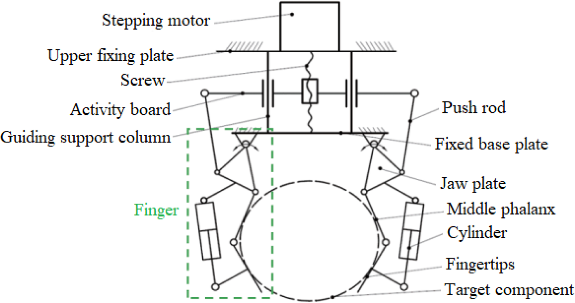
Schematic diagram of the structure of the double finger flexible manipulator.
The double-finger flexible manipulator designed in this study is suitable for gripping target components such as:
Target parts of different sizes and shapes; Target parts with high surface quality requirements; Thin walled and easily deformable target parts. Complete the gripping work of the target part with a size of 30–150 mm; Achieve precise control within a gripping force of 15–50 N; It has a position adjustment function of ± 10 mm in the horizontal direction.
The design objectives of a flexible manipulator are as follows:
Kinematics model of flexible manipulator
The simplified manipulator finger model in this study is shown in Figure 2. The Cartesian coordinate system of the manipulator finger is established, with the origin O as the center point of the chassis, point A as the center of the jaw hinge, and points B and C as the centers of the two hinges. The vertical line passing through the center of the manipulator palm is the y-axis, and the horizontal line passing through point O is the x-axis.

Geometric simplified model of finger unit of flexible manipulator.
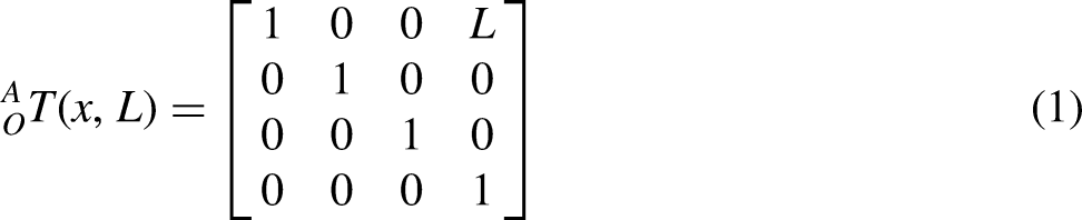
The point O is moved L along the x-axis to obtain the point A, and the coordinate transformation matrix is:


Clamping kinematics model of manipulator in slight deflection state
In practical applications, the gripping process of the manipulator is often in nonideal state, so it is particularly important to analyze the slightly deviated gripping posture of the manipulator.17,18 Taking the cylinder target as an example, the geometric modeling of the manipulator when clamping the cylinder offset is shown in Figure 3. When the flexible manipulator is gripping the target part, the line segment BC and CD are tangent to the cylindrical outer contour surface, the distance between the connection point C and the two contact points is equal, and the line connecting point C and the center of the cylinder is horizontal. The value of the gripping position point depends on the line segment EF. Since EF is not a fixed value, it can be replaced by a cylinder. The magnitude of cylinder pressure determines whether the length of E'F’ and EF is equal. If the pressure of the left and right cylinders is equal, then the flexible manipulator is in an ideal state for gripping the cylindrical target part, otherwise, it is in the offset gripping state.

The principal diagram of flexible manipulator clamping parts.
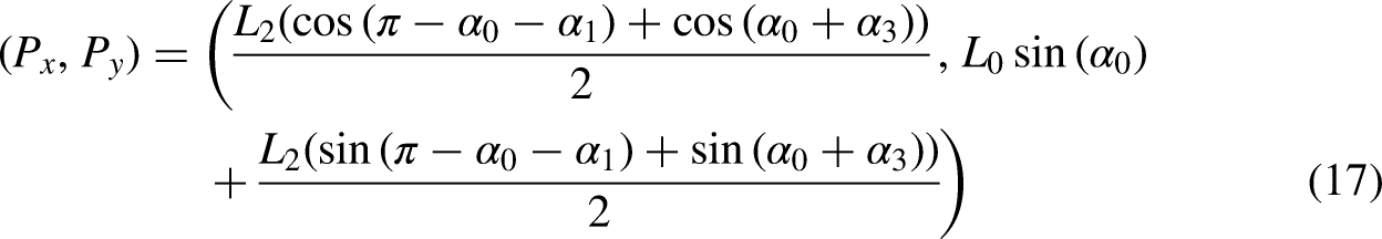
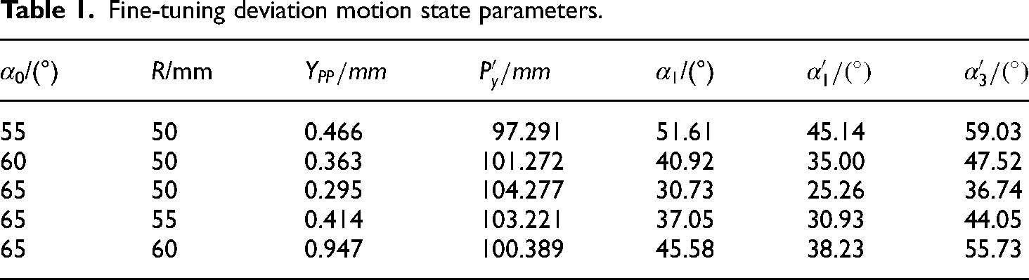
In case of slight deviation, kinematics state analysis is carried out based on the ABE segment. Assumed angle α0 is a known quantity, and the cylindrical parameters are the diameter R of the target part and the preset offset value s. The center coordinates of the target component for position fine-tuning offset are:


Fine-tuning deviation motion state parameters.
Structure design of double finger flexible manipulator
The structure diagram of the double-finger flexible manipulator is shown in Figure 4. The end fixed plate of the manipulator is fixedly connected to the manipulator by bolts. The angle adjustment of the mechanical finger is realized by the offset mechanism. The finger root drive mechanism pushes the finger forward and backward. The pressure sensor is fed back by the force on the mechanical finger, and the monitored clamping force value is input into the single-chip microcomputer. The single-chip microcomputer controls the electronically controlled pressure regulating valve to adjust the air pressure of the cylinder to control the clamping force of the manipulator.
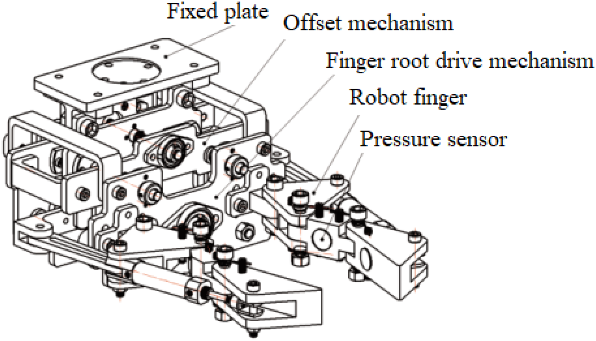
Overall structure of two-finger flexible manipulator.
The finger structure of the double-finger flexible manipulator includes the left claw, the right claw, and the claw fixing plate. The finger structure is divided into three parts: the root segment, the middle segment, and the tip segment. Each part is connected by a fixed pin shaft, and a torsion spring is installed between the root and middle finger joints. A torsion spring is installed between the middle finger joint and the fingertip joint. The two fingers are connected to the finger base fixing substrate by the finger base fixing seat. The structural diagram of the finger drive part of the manipulator is shown in Figure 5.

The structural diagram of the finger drive part of the manipulator.
The rotation angle of the finger joint is mainly adjusted by the screw nut driving the middle push plate forward and backward. The main motor fixing plate and finger root joint fixing plate are connected by fixing parts. The end of the main stepper motor screw rod is nested in the front fixed plate of the mechanical finger root drive part by a bearing seat. There is also a guide support column connection between the front and rear fixed plates of the finger root drive part, which ensures that the movable push plate in the middle slides in the direction of the guide column.
When the flexure manipulator clamps the cylindrical target part in nonideal situation, it will make the axis of the cylindrical part deviate from the ideal position, so to ensure the accuracy of the flexure manipulator clamping position, it is necessary to compensate the offset value. Based on the characteristics of the mechanical structure of the flexible manipulator, an additional manipulator damping and offset mechanism is designed, as shown in Figure 6.

Structural diagram of the offset damping mechanism of flexible manipulator.
The position adjustment part connector constitutes the frame of the fine-tuning mechanism by connecting the front fixing plate of the auxiliary motor and the rear fixing plate of the auxiliary motor, the guiding support column and the auxiliary displacement motors are fixed on the motor fixed plate. The compression spring and rubber shock-absorbing sleeve are socketed with the guiding support column to achieve the purpose of shock absorbing for the whole flexible gripper.
Simulation analysis of flexible manipulator
The three-dimensional model of the manipulator is imported into Adams to obtain the motion relationship, mechanical relationship and driving mode between the parts. The steps to establish a simulation model are as follows: (1) import a 3D model; (2) determine the specific motion form of the flexible manipulator to add constraints; (3) apply load; and (4) simulation analysis and data processing. After the modeling is completed, the grasping simulation of cylindrical parts and rectangular parts of the flexible manipulator is carried out.
According to the calculation of the object mechanics model for grasping rectangular components, the width and mass of the target component are positively correlated with the cylinder thrust. Therefore, it is inferred that changes in the width of the gripping target component will lead to changes in the gripping force. When grabbing a rectangular target, set the width of the target to 40, 45, and 50 mm, respectively. The initial mass of the target component is set to 0.6 kg, and the static friction coefficient between the finger and the object being grasped is 0.3. Create a rectangle with a width of 80 mm, a height of 45 mm, and a length of 120 mm in Adams. Set the distance between the upper surface of the rectangle and the lower surface of the manipulator fixing plate to 135 mm. The simulation diagram of the manipulator gripping a rectangular target component is shown in Figure 7.

The simulation diagram of manipulator gripping a rectangular target component.
The simulation results of torsion angle α0 are shown in Figure 8. It can be seen that the torsion angle α0 of the manipulator stays at the final position of 71° at the trajectory terminal of the target piece with a width of 50 mm, which is consistent with the theoretical calculation angle; α1 is the angle of the target component relative to the middle phalanx, which ultimately stabilizes at an angle of 180°.

Schematic diagram of torsion angle changes when gripping rectangular target components.
The mechanical model of the cylindrical target is built and the simulation analysis is carried out. The simulation effect of the manipulator clamping the cylindrical component is shown in Figure 9.

The simulation diagram of manipulator gripping a cylindrical target component.
The diameter and mass of the target component have an impact on the cylinder thrust, set the target part radius R = 50, 55, 60 mm, the mass of the target component to 0.6 kg, the static friction coefficient between the finger and the grasped object is 0.2. Create a cylinder with a radius of 50 mm, a height of 45 mm, and a translation pair with the earth in Adams. The theoretical calculation shows that the distance between the axis of the cylinder and the lower surface of the fixed plate of the manipulator is Y0 = 197 mm. As shown in Figure 10, when the manipulator clamps the target with a radius of 50 mm, the torsion angle ultimately stays at 55°, which is consistent with the preset angle. The distance between the target component and the manipulator coordinate XZ plane remains at 197.20 mm, and the theoretical calculation result is 197.24 mm, which is almost equal to the simulation result.

Schematic diagram of the change in torsion angle and spacing when the manipulator clamps a cylindrical component with a diameter of 100 mm.
When the flexible manipulator clamps a cylinder with a diameter of 100 mm, the variation of the clamping forces F1 and F2 between the middle and fingertip joints on the target component is shown in Figure 11. F1 represents the contact force between the mechanical fingertip and the clamped cylindrical part, passing through the cylindrical axis. F2 represents the contact force between the fingertip of the manipulator and the clamped cylindrical part. It can be seen that the two contact forces are almost equal and tend towards 21.95 N, indicating the correctness of the simulation results data.

The variation of the clamping forces F1 and F2 between the middle and fingertip joints on the target component.
Control system of double-finger flexible manipulator
The flowchart of the manipulator control system is shown in Figure 12. Due to the fact that the manipulator controller and the flexible manipulator controller are two independent control units, communication control circuits need to be built between the two. The manipulator controller and pressure sensor form a forward feedback circuit, which can effectively adjust the gripping force of the manipulator.

Manipulator control system flow diagram.
The circuit diagram of the control system is shown in Figure 13. The manipulator system body selects the ABB robot, the model is IRB2600, and the load is 12 kg. The manipulator pose state is established and the motion simulation is performed.

The circuit diagram of the control system.
The control flowchart of the flexible manipulator is shown in Figure 14. The flexible manipulator control system ensures the accuracy of clamping through the detection of pressure sensors. When building a pressure testing system, the sensor can be calibrated by adjusting the signal amplifier of the pressure sensor module. The three-dimensional model schematic diagram of the manipulator simulation system is shown in Figure 15, where the flexible manipulator is installed at the end of the manipulator.

Control flowchart of flexible manipulator.

Schematic diagram of 3D model of manipulator simulation system.
Due to errors in the manufacturing and installation of the double-finger flexible manipulator, there is a deviation between the actual clamping state and the measured value.19,20 Therefore, before the experiment, the measured dimensions are substituted into the corresponding calculation formula and corrected.
The design parameters and measured parameters of the manipulator are shown in Table 2. The torsion spring of a flexible manipulator may produce errors during the manufacturing and assembly process, which affect the initial state of the flexible manipulator. 21 The stiffness coefficients and initial angles of torsion springs are obtained through measurement, as shown in Table 3.
Comparison of design manipulator size and actual size.

Comparison of design value and actual value for manipulator torsion spring parameters.

After connecting the upper computer and lower computer of the flexible manipulator, the positioning and grasping test of the flexible manipulator is carried out on the PC operating interface. The control board controls the stepper motor driver and receives signal input from the pressure sensor. After setting the clamping position, the trajectory of the manipulator is programed and adjusted, and the control signal output is embedded in the program to indicate that the manipulator has reached the preset feeding position. The physical object and control system platform of the double-finger flexible manipulator are shown in Figure 16.

Experimental device for double finger flexible manipulator.
Clamping experiment of flexible manipulator
Experimental study on finger movement of finger flexible manipulator
The main stepper motor rotates to drive the push plate forward and backward through the ball screw, and the forward and backward movement of the push plate determines the opening and closing angle of the finger joint. Measuring the angle between the fingertip and the fingertip fixing plate of the double-finger flexible manipulator can effectively verify the motion accuracy of the fingertip during gripping. Figure 17 shows a comparison between the theoretical and actual values of finger root joint motion.

The relationship between the torsion angle and the moving distance of the push plate.
Where Yh refers to the movement distance of the root node push plate, α0 is the angle measurement angle of the root node. It can be seen that the actual value curve is close to the theoretical value curve, but both the upper and lower halves of the curve are offset. There are several reasons for this situation: (1) there is an assembly error between the finger root joint and the finger root fixing seat, which means there is a gap in the fit between the holes; (2) there is an assembly error between the push plate and the stepper motor connector, and there is a gap between the linear bearing and the guide support rod, which can also cause the push plate to move incorrectly; (3) the manufacturing error of calipers leads to inevitable measurement errors.
This study also conducted a mechanical arm gripping force test on cylindrical components, and the gripping force when gripping a cylindrical component with a diameter of 100 mm is shown in Figure 18. It can be seen that the actual value curves of F1 and F2 tend toward the theoretical value, but the actual value curves are all below the theoretical value, and the two actual value curves are not completely equal. There are several reasons for this situation: (1) there is friction force at the hinge of the fingertip and middle phalanx, which causes errors in actual testing. (2) There is a small pressure difference between the two cylinders, and under this effect, the clamping angle will change slightly, resulting in unequal values of F1 and F2. (3) The pressure sensor itself has measurement errors.

The relationship between gripping force and air pressure.
Experimental verification of grasping adaptability of double-finger flexible manipulator
The state diagram of the manipulator grasping target components with different shapes is shown in Figure 19. In Figure 19(a), the knuckles and fingertips are attached to the outer contour of the target component, that is, when gripping a rectangular component, the middle knuckles and fingertips are in a straight line state, achieving the attachment and gripping of the target component. In Figure 19(b), the target component has a mass of 300 g, an outer diameter of 90 mm, an inner diameter of 30 mm, and a thickness of 30 mm. The middle finger joint and fingertip joint are fitted to the outer contour of the target component, that is, the middle finger joint and fingertip joint present two intersecting lines to the cylindrical component, achieving the fitting and clamping of the target component.

Adaptability experiment of manipulator grasping components with different shapes. (a) Rectangular. (b) Cylinder.
In practical applications, the manipulator needs to achieve a fit to the outer profile of the target component, so the designed flexible manipulator adopts an indexable finger base.
Comparative experiment on clamping force when gripping cylindrical target components
This section compares the clamping force of the flexible manipulator according to the clamping force of cylindrical target parts and sets the cylinder air pressure at a maximum of 0.8 MPa. This study adopts a resistive pressure sensor, model FSR40-2, with a measurement accuracy of ±10 g.
The target object for the experiment is a cylindrical target has a diameter of 120 mm and a mass of 350 g. The locations of the force points on the middle knuckles and the finger root of the gripper hand when gripping the cylinder are determined. The sensor is attached to the middle and tip knuckles of the flexible gripping hand as shown in Figure 20(a). The clamping force test is carried out on a cylindrical target of 120 mm in diameter, and the cylinder thrust is adjusted by changing the air pressure value to change the clamping force of the jaws on the target. Figure 20(b) shows the experimental diagram of the clamping force measurement when the gripper clamps the cylindrical parts.

Clamping force experiment for clamping cylindrical target parts. (a) Position of the pressure senor. (b) Clamping force test.
The clamping force adjustment measurements are shown in Table 4, and the errors can be analyzed:
Friction exists at the articulation between the fingertip joint and the middle fingertip, which makes the error caused by the loss in the actual test; There is a deviation in the pressure of the two cylinders, and a slight change in the clamping angle under the action of a small pressure difference will also make the clamping force F1 and the clamping force F2 unequal; The pressure sensor itself has a certain measurement error. The pressure sensor is a resistive sensor, which has certain requirements on the contact surface. If the contact surface is uneven, the measurement accuracy will be affected, thus affecting the overall measurement results.
Measurement parameters of the clamping force of the flexible manipulator.

Conclusion
This study analyzes the design principle of flexible manipulator and establishes a mathematical model. By innovative structural design, the gripping range and gripping adaptability of flexible manipulator is improved. The clamping state and working characteristics of the flexible manipulator when clamping different target parts are described by MATLAB.
The statics and kinematics of flexible manipulator gripping the target parts with different shapes are analyzed. The three-dimensional model of the flexible manipulator is established. The theoretical model of the flexible manipulator clamping different target parts is verified by Adams, and the kinematics of the flexible manipulator is analyzed.
The flexible manipulator experimental platform was built for gripping experiments, and the manipulator can easily grip a cylindrical target with a mass of 300 g. The experiment shows that the theoretical value of the clamping force is basically consistent with the experimental value. The flexible manipulator has good grasping adaptability for target parts of different sizes, shapes, and materials.
Footnotes
Declaration of conflicting interests
The authors declared no potential conflicts of interest with respect to the research, authorship, and/or publication of this article.
Funding
The authors disclosed receipt of the following financial support for the research, authorship, and/or publication of this article: the soft science research program project of Henan province; key scientific and technological projects of Henan province (Grant No. 232102320008); and key scientific research projects of universities in Henan province (Grant No. 24B170004).