
Abstract
To improve the dynamic response performance of a high-flow electro-hydraulic servo system, scholars have conducted considerable research on the synchronous and time-sharing controls of multiple valves. However, most scholars have used offline optimization to improve control performance. Thus, control performance cannot be dynamically adjusted or optimized. To repeatedly optimize the performance of multiple valves online, this study proposes a method for connecting a high-flow proportional valve in parallel with a low-flow servo valve. Moreover, this study proposes an algorithm in which a proportional–integral–derivative system and multivariable predictive control system are used as an inner loop and outer loop, respectively. The simulation and experimental results revealed that dual-valve parallel control could effectively improve the control accuracy and dynamic response performance of an electro-hydraulic servo system and that the proportional-integral-derivative–multivariable predictive control controller could further dynamically improve the control accuracy.
Keywords
Introduction
Because of the development of electro-hydraulic servo technology,1–3 multiple hydraulic valves have been widely used to drive an actuator in parallel, and scholars have achieved favorable results by using this method in some engineering applications.
Currently, the multivalve parallel control of an electro-hydraulic servo system is implemented using two approaches. In the first approach, multiple heterogeneous parallel valves are operated using a time-sharing approach.4–6 For example, Bai and Quan 5 proposed a new hydraulic control circuit with two valves arranged in parallel for jointly controlling the actuator. Ren and Ruan 6 used an improved two-dimensional valve as the primary control component, which was connected in parallel with a servo valve to obtain high-frequency vibration. In the second approach, multiple isomorphic parallel valves are operated synchronously. Hodgson et al. 7 connected four solenoid valves in parallel for time-sharing control to improve the stability and control accuracy of a closed-loop system.
Although the aforementioned control schemes provide solutions specific to certain applications, they cannot dynamically adjust the performance of multiple valves. Therefore, in this study, a control method that achieved the online and repeated optimization of the control performance was designed. Because predictive control can provide real-time optimal control under the constraint conditions through a predictive model, rolling optimization, and feedback correction, a dual-valve proportional-integral-derivative (PID)–multivariable predictive control (MPC) algorithm based on predictive control is proposed.8–12 The PID–MPC controller uses the PID and MPC systems as the inner and outer loops, respectively.
This article is organized as follows: In section “Mathematical model of the dual-valve parallel electro-hydraulic servo system,” the mathematical model of the electro-hydraulic servo system using proportional and servo valves is provided. In section “PID–MPC composite algorithm for dual-valve parallel control,” the PID–MPC composite control algorithm is outlined. Section “Simulation” discusses the PID–MPC control simulation model established using Siemens AMESim and MathWorks MATLAB/Simulink. Section “Experimental results” presents the experimental verification of the slope tracking accuracy of PID–MPC control. Finally, the conclusions are provided in section “Conclusion.”
Mathematical model of the dual-valve parallel electro-hydraulic servo system
As displayed in Figure 1, the dual-valve parallel electro-hydraulic servo system primarily comprises a servo valve, proportional valve, hydraulic cylinder, displacement sensor, and controller. The controller sends a control command to the servo and proportional valves, which generates movement in the piston rod of the hydraulic cylinder. The displacement sensor continuously detects the position of the piston rod and provides feedback to the controller.

Schematic of the dual-valve parallel electro-hydraulic servo system.
First, single-valve control was considered. According to the operational characteristics of a hydraulic spool valve, the linear flow equation is obtained as follows

where
On the basis of the flow continuity equation, the following equation can be obtained
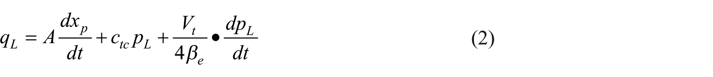
where

where

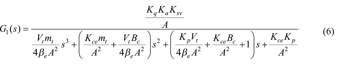
On the basis of the aforementioned equations, the following equation can be obtained
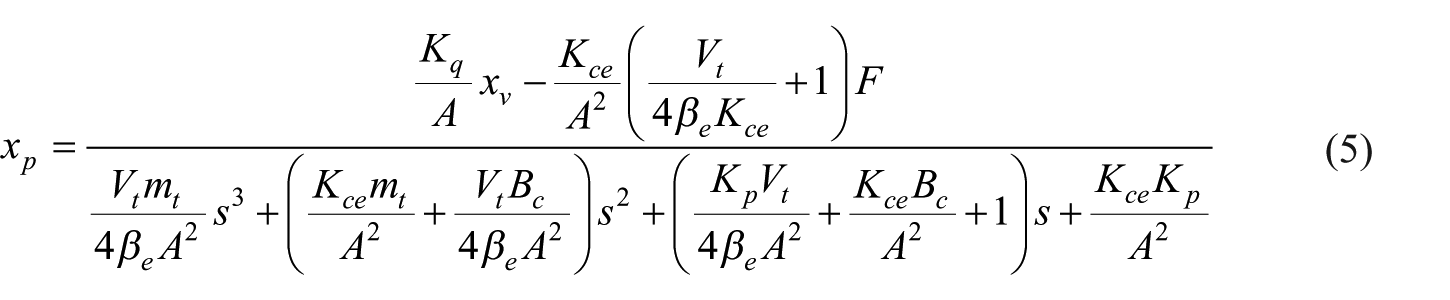
where
where
By neglecting the nonlinear coupling between the proportional and servo valves, the flow equation representing the parallel connection of the two valves obtained using a linear superposition method is as follows

where

where
PID–MPC composite algorithm for dual-valve parallel control
According to the mathematical model presented in section “Mathematical model of the dual-valve parallel electro-hydraulic servo system,” the dual-valve parallel electro-hydraulic servo system is a two-input single-output system. Figure 2 illustrates the PID–MPC composite control algorithm. As displayed in the figure, the PID–MPC composite control algorithm comprises the PID control system as the inner loop and MPC system as the outer loop, respectively.

Block diagram of PID–MPC composite control.
A dynamic matrix control (DMC) algorithm was used to design the system controller.13,14 First, the prediction model was developed. A step response was sampled for each closed-loop control system in the inner-loop system, and the sample values of input
At time

where

and

where A11 and A12 are the dynamic matrices comprising
The rolling optimization strategy of the system was determined. In rolling optimization, the changes in

The index can be given in a vector form as follows

where
A large weight of the element
The high-flow proportional valve cannot track a target curve, which abruptly varies because of the low response frequency and dead zone of the valve. Therefore, the value of
The constraints of


Equations (13) and (14) were incorporated into the rolling optimization equation as follows


where
For optimization problems involving quadratic properties with inequality constraints, quadratic programming (QP) 15 can be used to obtain the optimal solution.
Finally, after developing the prediction model and rolling optimization, feedback correction was added to the algorithm. Thus, the system could be adjusted according to the actual output. The error vector calculated at time

According to equation (17), the predicted output of the corrected system is as follows

where
The predicted value

where
Simulation
Simulink modeling for dual-valve parallel PID–MPC composite control
The Simulink model of the PID–MPC composite algorithm for dual-valve parallel control was developed (Figure 3(a)) according to the mathematical model and PID–MPC composite algorithm presented in sections “Mathematical model of the dual-valve parallel electro-hydraulic servo system” and “PID–MPC composite algorithm for dual-valve parallel control,” respectively.

PID–MPC composite algorithm for dual-valve parallel control: (a) Simulink model and (b) results.
Figure 3(b) confirms the effectiveness of the PID–MPC composite algorithm; here,
In order to avoid too complex mathematical modeling, the nonlinear factors such as dead zone and maximum flow limit of the valves are neglected, resulting in the fact that Figure 3(b) cannot reflect the actual characteristics of proportional and servo valves, for example, a significant deviation between
AMESim–Simulink co-simulation modeling for single-valve control
First, the proportional valve was used for establishing the single-valve simulation model.
Figure 4 depicts the AMESim–Simulink co-simulation model of the proportional valve (similar to that of the servo valve). The primary parameters were as follows: The flow rate of the plunger pump was 15.8 L/rev, relief valve opening pressure was 140 bar, signal of the proportional valve was ±40 mA, response time was less than or equal to 60 ms, dead zone was 20% of the valve stroke, and maximum flow rate was 30 L/min at a P–T pressure drop of 70 bar. The input signal of the servo valve was ±40 mA, and the response time was less than or equal to 10 ms for a natural frequency of 62 Hz and maximum flow rate of 8 L/min at a P–T pressure drop of 70 bar. The diameters of the cylinder, piston rod, and stroke were 100, 50, and 200 mm, respectively. The initial position was at 100 mm, and the weight was 100 kg. The parameters of the PID controller of the proportional control loop were as follows:

AMESim–Simulink co-simulation model for proportional valve: (a) AMESim model and (b) Simulink model.
Figure 5 displays the step response curve of the proportional and servo control loops. The amplitudes of the proportional and servo control loops were 1 and 0.2 mm, respectively. In Figure 5,

Step response curve for single-valve control.
The sampling period was set to 0.01 s. The value of the modeling time domain

where
AMESim–Simulink co-simulation modeling for dual-valve parallel PID–MPC control
Figure 6 displays the simulation model for dual-valve parallel PID–MPC composite control (similar to the model of PID control). The parameters of the simulation were the same as those for single-valve control.

AMESim–Simulink co-simulation model for dual-valve parallel PID–MPC composite control: (a) AMESim model and (b) Simulink model.
Figure 7 illustrates the slope-tracking inputs of the PID and PID–MPC controls. The parameters in the PID control were adjusted as follows:

Input of slope tracking: (a) PID control and (b) PID–MPC control.
Figure 8 illustrates the slope-tracking output for proportional PID control, dual-valve PID control, and dual-valve PID–MPC control. In the figure,

Output of slope tracking for the three control methods.
Figure 9 presents the sinusoidal tracking input of dual-valve PID control and dual-valve PID–MPC control. The frequency and amplitude were 10 Hz and 1 mm, respectively. The parameters in PID control were adjusted as follows:

Input of sinusoidal tracking: (a) dual-valve PID control and (b) dual-valve PID–MPC control.
Figure 10 illustrates the sinusoidal tracking curves for single proportional valve control, dual-valve PID control, and dual-valve PID–MPC control. The figure indicates that the sinusoidal tracking curve for single proportional valve control had a large phase deviation. The tracking deviation caused by the dead zone is particularly evident near the peak of the curve. Although dual-valve PID control reduced the amplitude deviation, a large phase deviation was observed. Dual-valve PID–MPC control exhibited significant improvement in the control accuracy from the second cycle, which indicated that PID–MPC control can reduce the phase deviation and improve the dynamic performance of the system.
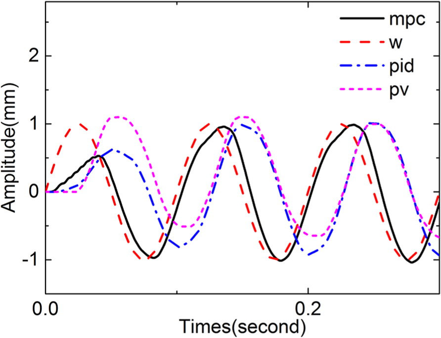
Sinusoidal tracking curves for the three methods.
Experimental results
After simulation, the proposed method was verified using an experimental platform.
Figure 11 depicts the electro-hydraulic servo testing machine. The testing machine comprised a testing machine body, control cabinet, industrial personal computer, and hydraulic station. The hydraulic cylinder was driven by the proportional valve ATOS DLHZO-AE-071-L1 and servo valve ATOS DHZO-TE-040-L01. The response time of the proportional valve was less than or equal to 30 ms, and the dead zone was 20% of the valve stroke. The response time of the servo valve was less than or equal to 10 ms. The dynamic responses for the ±100% and ±5% rated strokes were 62 and 180 Hz, respectively.

Electro-hydraulic servo testing machine.
Figure 12 illustrates the experimental curve of slope tracking for single proportional valve control, dual-valve PID control, and dual-valve PID–MPC control. In the figure, w is the target curve, whereas mpc, pid, and pv are curves for PID–MPC control, PID control, and single proportional valve control, respectively. Figure 13 displays the deviation curve of the slope tracking for the three control methods.

Experimental curve of slope tracking.

Deviation curve of slope tracking.
As displayed in Figure 12, the slope tracking curve for single proportional valve control and the target curve exhibited a constant deviation because of the dead zone. Figure 13 indicates that PID control considerably reduced the tracking error; however, its initial tracking error was still 1.2 mm. The deviation of PID–MPC control was very close to zero except initially, when deviation was 0.15 mm.
Figures 14 and 15 illustrate the experimental curves of slope tracking for the three control methods and the deviation curve, respectively. The frequency and amplitude of the target sinusoid were 1 Hz and 5 mm, respectively. Figures 14 and 15 indicate that single proportional valve control could not accurately track the target curve because of the low-frequency response of the proportional valve. Furthermore, the curve for dual-valve PID control was close to the target curve except at the peak position. The deviation of dual-valve PID–MPC control could be maintained in the range of 0–0.25 mm, which indicated that the rolling optimization of dual-valve PID–MPC control could effectively suppress the influence of the dead zone on the control accuracy.
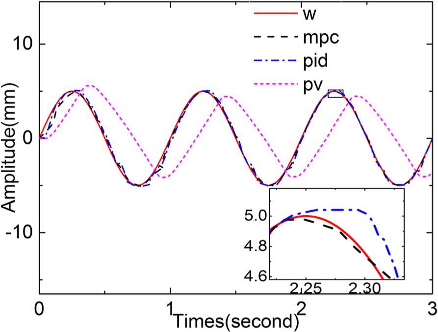
Experimental curve of sinusoidal tracking.
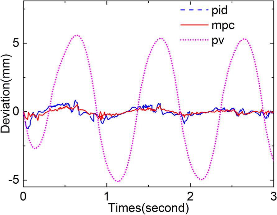
Deviation curve of sinusoidal tracking.
The integrated time and absolute error (ITAE) 16 was used to quantitatively evaluate the tracking accuracy of the three control methods. The equation is as follows

where the upper limit of integral
Table 1 summarizes the ITAE deviations for the three methods. According to the conducted slope tracking, the accuracy of dual-valve PID control was 39.3% higher than that of single proportional valve control, whereas the accuracy of dual-valve PID–MPC control was 79.6% higher than that of single proportional valve control. Similarly, according to the conducted sinusoidal tracking, the accuracy of dual-valve PID control was 75.5% higher than that of single proportional valve control, whereas the accuracy of dual-valve PID–MPC control was 90.0% higher than that of single proportional valve control.
ITAE indicator under different control methods.

ITAE: integrated time and absolute error; PID: proportional–integral–derivative; MPC: multivariable predictive control.
Conclusion
Few studies have examined the dynamic optimization of the control performance of a multivalve parallel electro-hydraulic servo system. In this study, a new parallel method and control algorithm were designed. The contributions of this study are as follows:
A technical solution is proposed by connecting a high-flow proportional valve with a low-flow servo valve. For predictive control, a dual-valve parallel PID–MPC composite control algorithm was designed with PID and MPC systems as the inner and outer loops, respectively.
The simulation and experimental results revealed that dual-valve PID control could effectively improve the control accuracy and dynamic response performance of the electro-hydraulic servo system to a certain extent. Moreover, the PID–MPC control algorithm proposed in this study could efficiently utilize the advantages of the servo and proportional valves by conducting rolling optimization, thereby further dynamically improving the control accuracy of the system.
Footnotes
Declaration of conflicting interests
The author(s) declared no potential conflicts of interest with respect to the research, authorship, and/or publication of this article.
Funding
The author(s) disclosed receipt of the following financial support for the research, authorship, and/or publication of this article: This work is supported in part by the National Natural Science Foundation of China (Grant No. 51705214) and National Quality Technology Infrastructure Construction Project of Zhejiang Quality Supervision System (Grant No. 20180129).