
Abstract
A typical serial manipulator consists of a servo motor, a serial mechanism and an independent joint placed between the motor and the serial mechanism. Both the time-varying characteristics of the inertia of the serial mechanism and the flexibility characteristics of the independent joint are widely found in serial manipulator servo drive systems. These two characteristics not only increase the resonance magnitude of serial manipulators, but also affect the dynamic characteristics of the system. In order to obtain a stable output speed of serial manipulators, the variable parameters of a PI control strategy is applied to a serial manipulator servo drive system. Firstly, dynamic model of a serial manipulator servo drive system is established based on a two-inertia system. Then the transfer function from motor speed to motor electromagnetic torque is derived by the state-space equation. Furthermore, the parameters of the PI controller are designed and optimized utilizing three different pole assignment strategies with the identical radius, the identical damping coefficients, and the identical real parts. The results indicate that a serial manipulator servo drive system can obtain good dynamic characteristics by selecting parameters of the PI controller appropriately.
Keywords
Introduction
Serial manipulators are widely used for many other aspects, such as industrial assembly, aeronautics and space exploration, national defense and security and so on. A serial manipulator is a complex system with multiple inputs and outputs, which contains high nonlinearity and strong coupling. A serial manipulator is composed of different links to form a kinematic chain, thereby realizing different motion rues of the end effector. Due to the change of the locations of each link during the movement of the end effector, the rotation radius of the center of mass in the serial manipulator is changed. Therefore, the inertia of serial manipulator servo drive systems has obvious time-varying characteristics. The time-varying characteristics of the inertia cause fluctuations in the output speed of the serial manipulator servo drive systems. Besides, the two links are connected by contact at independent joints. The flexibility of independent joints is a factor that cannot be ignored for many high-performance serial manipulators. The causes of this flexibility are very complicated, including the elasticity of gears, couplings, ball screws in the drive system, and the torsional stiffness of the drive shaft itself. The existence of this joint flexibility can cause resonance of the serial manipulator servo drive system, and resonance magnitude and can be reflected by the dynamic response of the system. This resonance will affect the dynamic accuracy of the serial manipulator and even damage it.1–3 Since the time-varying characteristics of the inertia and the flexibility characteristics of the independent joint increase the control difficulty. Therefore, it is important to control the speed and resonance of the serial manipulator. Many scholars have studied the modeling and control methods of the serial manipulator servo drive system.
Regarding the modeling of the serial manipulator servo drive system, Mark W. Spong first proposed that the system could be equivalent to a damping spring connection between the motor and the serial mechanism, thus forming a double-inertia system.4,5 Generally, the control methods of the two-mass system mainly include active control and passive control strategy. The active control strategy is to change the parameters of the controller or the structure of the controller to eliminate the influence of resonance, mainly including PI, PRC, RRC, robust control, state feedback control, etc. The literature6–15 adopts this control strategy. The literature6,10 uses the PI control strategy to control the speed loop in the servo drive system, to reduce resonance. The literature7,8,11 adopts the robust control strategy to reduce resonance. The literature 9 adopts a state feedback control strategy and USES the state space control method in speed loop control to reduce resonance. The literature12–15 adopts the modern control theory to improve the stability of the system. The passive control strategy is to insert a notch filter between the output of the speed loop and the current loop, mainly including a frequency notch filter, low-pass filter, and adaptive notch filter, etc. This control strategy is adopted in the literature.16,17 In serial manipulator servo drive system, PI control is still the most widely used control strategy, especially suitable for high performance servo drive systems. By designing PI controller parameters, the serial manipulator servo drive system can obtain good dynamic characteristics.
Given the influence of the time-varying characteristics of the inertia on system control, some scholars have gradually attracted attention. The literature 18 discussed the influence of the time-varying characteristics of the inertia about the parallel robot to the control of the dual inertia system. In the serial manipulator servo drive system, the inertia of the serial manipulator changes with locations, thereby causing the system inertia ratio to change. This change in the inertia ratio will affect the dynamic response of the serial manipulator servo drive system. Besides, with the same control coefficient, the change of inertia ratio will cause the change of dynamic response characteristics of the system. This leads to resonance and affects the stability of the serial manipulator servo drive system.
In this paper, the dynamic model of the serial manipulator servo drive system is established at first. Combined with the literature,2,19,20 pole assignment strategies were proposed to determine the PI controller parameters. For each pole placement strategy, the effects of the damping coefficient and natural frequency of the pole on system characteristics are analyzed. Finally, the trend time-varying of the inertia of the serial mechanism is illustrated through a design example of controller parameters of PUMA560 serial manipulator. The motor speed output of the serial manipulator servo drive system is obtained by simulation. The results show that the method of PI controller parameter setting based on pole assignment is effective.
The main contributions of this paper include the independent joint dynamic model establishment considering the flexibility characteristics, the PI control strategy using the pole assignment strategies to obtain a stable output speed of serial manipulators, as well as the parameters of the PI controller selecting according to the pose of serial manipulators. The rest parts of the paper are organized as follows: Section 2 establishes the independent joint dynamic model. Section 3 introduces the PI Control Strategy. Section 4 uses the pole assignment strategies to determine controller parameters. Section 5 carries out the analysis of numerical simulation of the serial manipulator servo drive system. Section 6 states the conclusion.
Serial manipulator servo drive system modeling
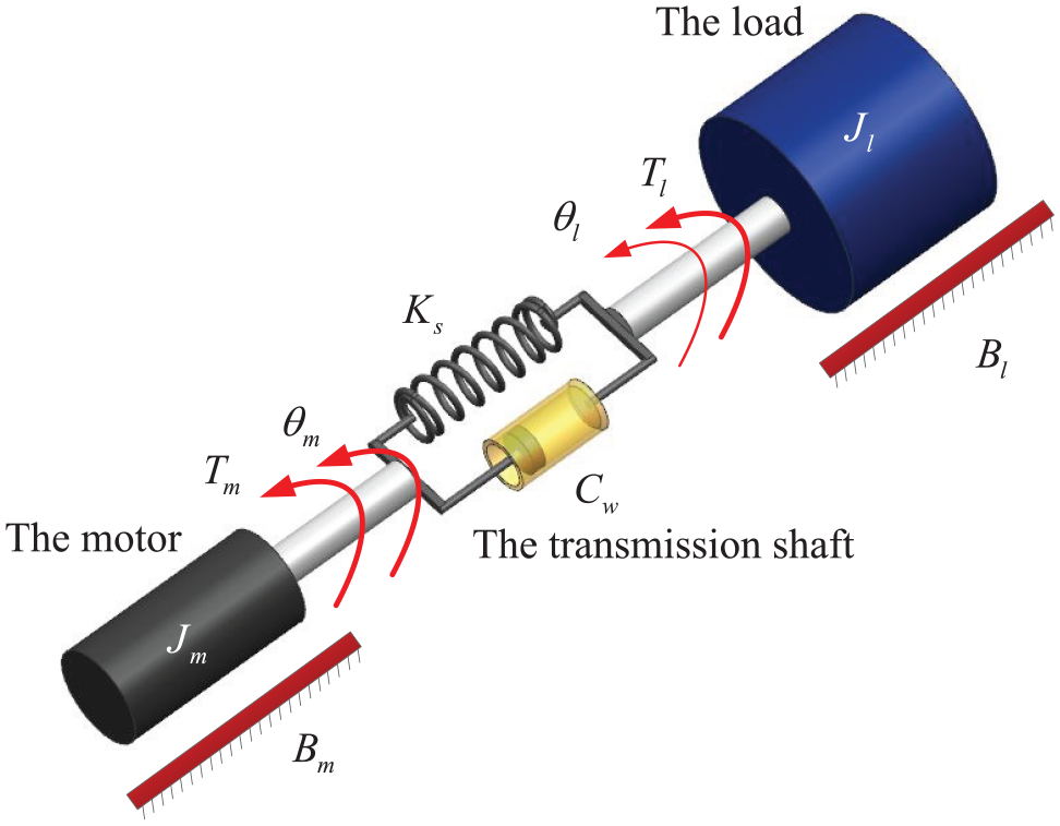
In a serial manipulator servo drive system, a servo motor is connected to a serial mechanism as shown in Figure 1. The motor and the serial mechanism are connected by a drive shaft or an elastic coupling. Since the drive shaft system or the elastic coupling has torsional stiffness and damping, it can be equivalent to a spring with damping. One side of the spring is connected to the motor and the other side is connected to the serial mechanism. Thus, the motor and the serial mechanism constitute a double inertia system, as shown in Figure 2. The links and their end-effectors in the serial manipulator have corresponded to the load side of the double inertia system.

Model diagram of the serial manipulator servo drive system.
Model of a two-inertia-system.
The links and their end-effectors perform regular movement. Assuming that the mass of the links is concentrated at the center of mass, the inertia of the serial mechanism depends on its radius of gyration. Therefore, the inertia of the serial mechanism varies in different poses. In a serial manipulator servo drive system, there are two inertias in the motor. The first one is the inertia of the motor itself. The second one is the inertia of the serial mechanism, which relates to the element of the manipulator inertia matrix and reduction ratio. Therefore, the inertia of the motor is as shown in Eq. (1).

here
The dynamic equation of the serial manipulator servo drive system is shown in Eq. (2).

here
According to the literature,2,20,21 the damping coefficient of the system is ignored. The dynamic equation of the system is shown in Eq. (3).
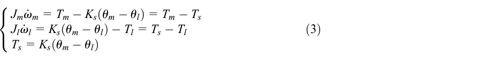
here
According to Eq. (3), the state space equation of the system and the control block diagram of the serial manipulator servo drive system are obtained. The state-space equation is shown in Eq. (4), and the control block diagram is shown in Figure 3.

According to Eq. (4), the control block diagram is shown in Figure 3. The transfer functions of the motor speed to the motor electromagnetic torque can be obtained as shown in Eq. (5).


Control diagram of a two-mass system.
Eq. (5) is expressed as the form shown in Eq. (6).

here


According to Eq. (8), the relationship among the resonance frequency, the anti-resonance frequency, and the inertia ratio can be obtained, as shown in Figure 4. It shows that the inertia ratio directly affects the resonance magnitude and stability of the system.
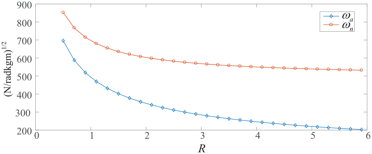
Relationship among the resonance frequency, the anti-resonance frequency and the inertia ratio.
PI control strategy
According to the double closed-loop control strategy of a servo motor, the PI controller is used for control. The control diagram of a serial manipulator servo drive system is shown in Figure 5. Where

Control diagram of the manipulator servo drive system.
It is assumed that the current loop has completed the adjustment when the speed loop is adjusted. So the influence of the current loop can be ignored. 20 Regardless of the influence of the current loop, the speed loop diagram of the PI controller of the two-mass system is derived and shown in Figure 6.

The speed control of the serial manipulator servo drive system.
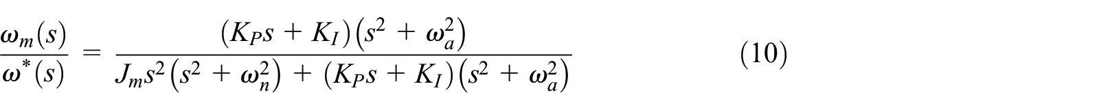
Ignoring the influence of the current loop, the closed-loop transfer function of the serial manipulator servo drive system, which adopts the PI controller, is shown in Eq. (10).
here
In this paper, pole assignment strategies, that proposed in the literature,2,19 were used for configuring the pole. The denominator polynomial in the closed-loop transfer function Eq. (10) of the system was written as Eq. (11). Equation (11) could be obtained through the change of Eq. (12).

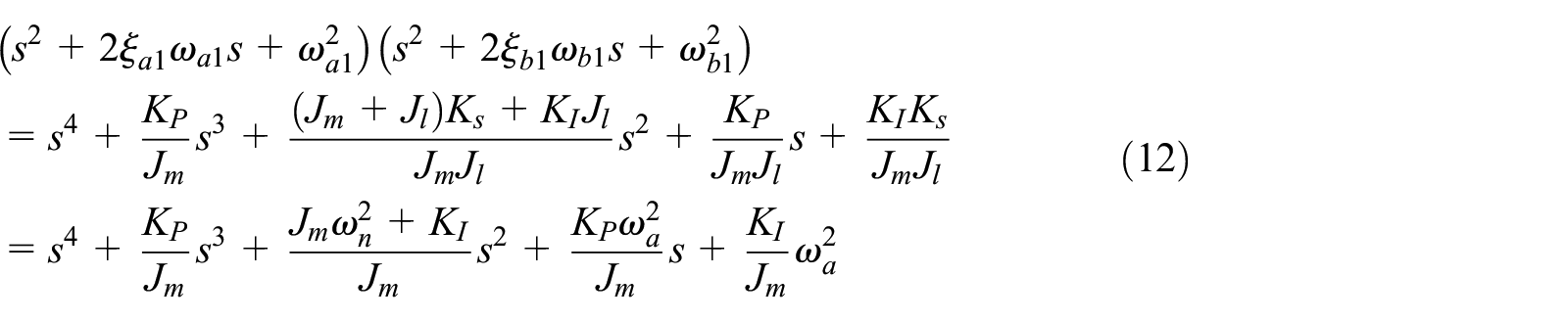
here
According to the equality of corresponding coefficients in Eq. (11), Eq. (13)–(16) express as follows.


Therefore, the closed-loop transfer function of the serial manipulator servo drive system can be written as Eq. (17).

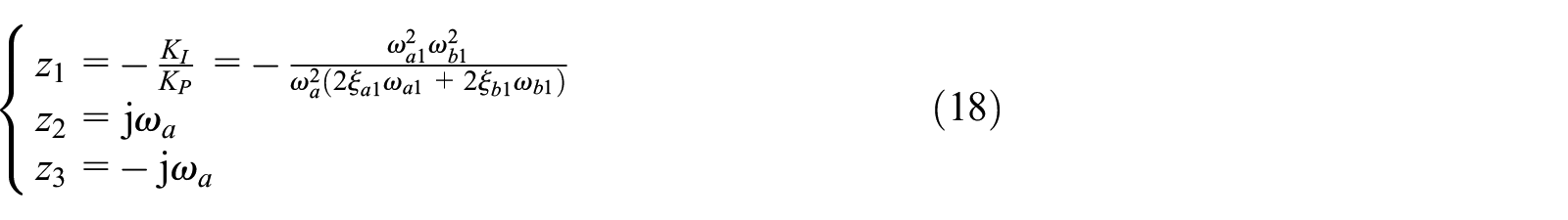
The solution of the zero-point equation of the closed-loop transfer function of the system is shown in Eq. (18).
PI controller parameters setting method based on pole assignment
The parameters of the PI controller directly affect the output of a serial manipulator servo drive system. Therefore, the stability of the output of the system can be improved by reasonably selecting the PI controller parameters. The inertia of the serial mechanism shows obvious time-varying characteristics due to the pose transformation of the serial mechanism in the working space. The time-varying characteristics of the inertia of the serial mechanism can cause resonance. The parameters of the PI controller are changed in real-time during the movement of the serial manipulator to obtain a stable output. The controller parameters depend on the inertia of the serial mechanism. The design procedure of the PI controller is shown in Figure 7.
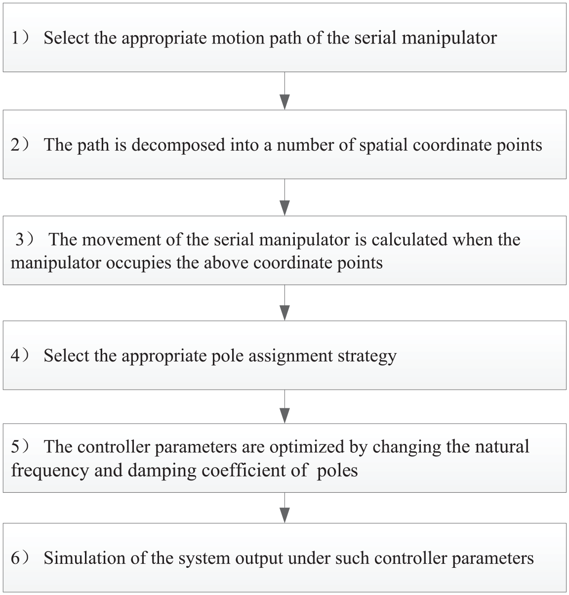
The design procedure of the PI controller.
The PI controller parameters can be calculated by using pole assignment strategies according to Eq. (13)–(16). There are three pole assignment strategies to design the PI controller parameters in this paper. The classification is based on the difference between the limiting conditions of poles. The parameters selecting methods are described as follows.
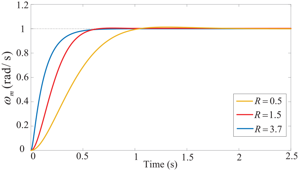
Pole assignment strategy with the identical radius
Many poles can be obtained by designing the natural frequency and the damping coefficient of the pole in a serial manipulator servo drive system. These poles of the closed-loop transfer function which have identical radius can be assigned by this strategy. The distribution of the zero poles of this pole assignment strategy is shown in Figure 8.
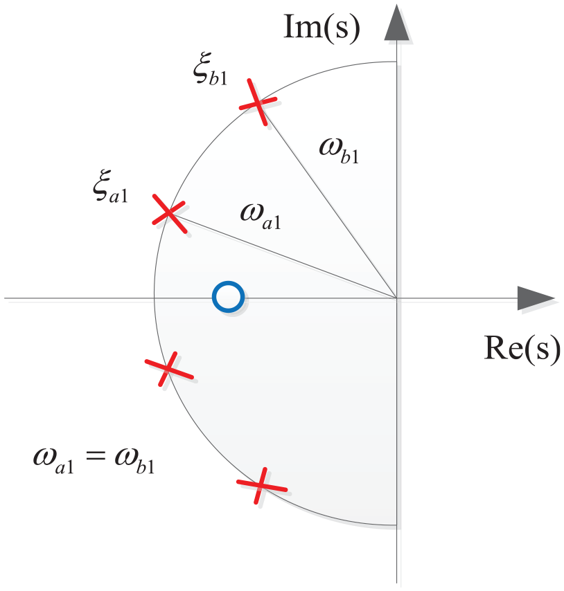
Schematic diagram of the pole assignment strategy with the identical radius
Equation (19)–(22) can be obtained by substituting


The zero point of the closed-loop transfer function of the serial manipulator servo drive system is shown in Eq. (23).

The numerical value of the damping coefficient of the pole determines the maximum overshoot, peak time and adjustment time of the system, as shown in Figure 9.
System evaluation index diagram of the pole assignment strategy with the identical radius.
The maximum overshoot reflects the dynamic accuracy of the system. The smaller in the maximum overshoot reflects the more stable in the system. From the Figure 9, it can be concluded that when the value of the damping coefficient of the pole is smaller, the maximum overshoot of the system is larger and the adjustment time is shorter. In this case, the system needs a long time to reach a stable state and the system stability is poor. The maximum overshoot, peak time and adjustment time of the system do not change much when the value of the damping coefficient of the pole increases gradually. The variation trend of the maximum overshoot with the damping coefficient of the poles matches well with the literature. 19
With the change of the damping coefficient of the poles, the distribution of zero poles of the system is shown in Figure 9. The direction of the arrow is the direction in which the damping coefficient increases.
From the distribution rule of zero poles in Figure 10, it can be concluded that under this pole assignment strategy, the following conclusions are as follows:
In the case that the closed-loop transfer function of the serial manipulator servo drive system has the same damping coefficient of poles, the zero point gradually approaches the imaginary axis with the increase of inertia ratio. When the inertia ratio exceeds 1, the poles distribution law does not change with the increase of the inertia ratio. However, when the inertia ratio is less than 1, some poles change from an imaginary number to a real number with the increase of the inertia ratio. This indicates that the system has an under-damped state to an over-damped state or a critically damped state.
In the case of a certain inertia ratio, the zero point gradually moves away from the imaginary axis as the damping coefficient of poles increases; the real part of the pole gradually decreases, and the imaginary part gradually decreases. This implies that the poles gradually move away from the imaginary axis. This indicates that the rapidity of the system is reduced. This conclusion is consistent with the trend that the system peak time increases with the increase of the damping coefficient of poles in Figure 9(b).
The amplitude of the poles is equal to the resonant frequency.

Distribution of zero poles in the pole assignment strategy with the identical radius.
Pole assignment strategy with the identical damping coefficients
These poles of the closed-loop transfer function which have identical damping coefficients can be assigned by this strategy. The distribution of the zero poles of this pole assignment strategy is shown in Figure 11.

Schematic diagram of pole assignment strategy with the identical damping coefficients.
Substituting


After further simplification, Eq. (26) and Eq. (27) can be obtained.


Therefore, Eq. (28) and Eq. (29) exist.


The zero point of the closed-loop transfer function of the serial manipulator servo drive system is shown in Eq. (30).

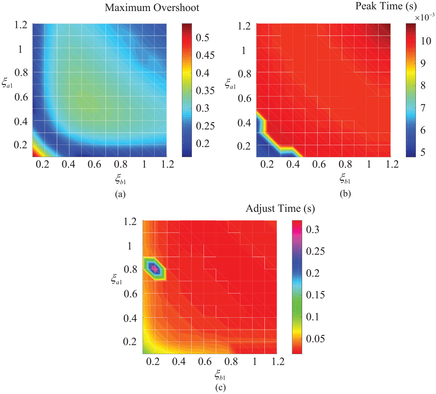
The numerical value of the damping coefficient of the pole and ratio of the natural frequency of the pole determines the maximum overshoot, peak time and adjustment time of the serial manipulator servo drive system, as shown in Figure 12.

System evaluation index diagram of the pole assignment strategy with the identical damping coefficients.
It can be concluded from Figure 11 that the numerical value of the damping coefficient of the pole is smaller and the maximum overshoot of the system is larger. At this time, the system takes a long time to reach a stable state. So the serial manipulator servo drive system stability is poor. With the increase of the damping coefficient of the poles, the overshoot of the system decreases gradually. When the damping coefficient of the pole exceeds 0.6, the maximum overshoot, peak time and adjustment time of the system do not change much. The serial manipulator servo drive system is stable at this time. The ratio of the natural frequency of the poles has little influence on the overshoot and adjustment time of the system. However, when the ratio is 2.5, the peak time of the system suddenly increases and the system rapidity decreases.
With the change of the damping coefficient of the poles, the distribution of zero poles of the system is shown in Figure 13. The direction of the arrow is the direction in which the damping coefficient increases.

Distribution of zero poles in the pole assignment strategy with the identical damping coefficients.
From the distribution rule of zero poles in Figure 13, it can be concluded that under this pole assignment strategy, the following conclusions are as follows:
As shown in Figure 13(b), with a certain damping coefficient of the poles, the dominant pole of the system gradually approaches the imaginary axis as the inertia ratio increases. But the change that the zero point of the system tends to approach the imaginary part is not obvious. Both the dynamic response of the system and degree of resonance decrease in this case.
In the case of a certain inertia ratio, with the increase of the damping coefficient of the pole, the system poles are away from the imaginary axis, and the dynamic response of the system is accelerated.
Pole assignment strategy with the identical real parts
These poles of the closed-loop transfer function which have identical real parts can be assigned by this strategy. Based on this, the position of the system zero can be determined. The pole placement of this pole placement method is shown in Figure 14.

Schematic diagram of the pole assignment strategy with the identical real parts.
Substituting


After further simplification, Eq. (33) and Eq. (34) can be obtained.


Therefore, Eq. (35) and Eq. (36) exist.


The zero point of the closed-loop transfer function of the serial manipulator servo drive system is as shown in Eq. (37).

The numerical value of the damping coefficient and the ratio of the natural frequency of the poles determine the maximum overshoot, peak time and adjustment time of the system, as shown in Figure 15.
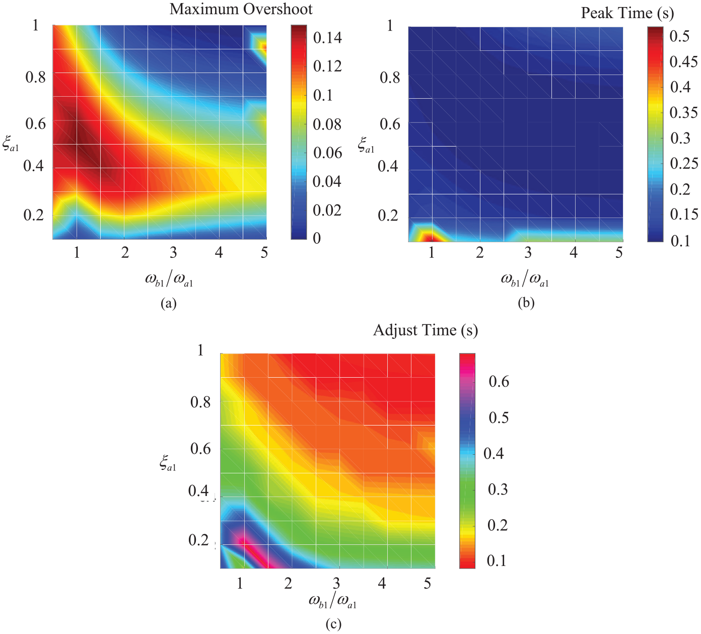
System evaluation index diagram of the pole assignment strategy with the identical real parts.
Figure 15 shows that when the numerical value of the damping coefficient and the ratio of the natural frequency of the poles are smaller, the maximum overshoot of the system is larger. When the numerical value of the ratio is equal to 1, the maximum overshoot of the system is the largest. When the numerical value of the ratio is no variety, with the gradually increasing of the damping coefficient of the pole, the system overshoot is gradually decreased. When the ratio is large, the system overshoot and adjustment time has little effect. But when the ratio is small, the maximum overshoot of the system changes greatly.
With the change of the damping coefficient of the poles, the distribution of zero poles of the serial manipulator servo drive system is shown in Figure 16. The direction of the arrow is the direction in which the damping coefficient increases.

Distribution of zero poles in the pole assignment strategy with the identical damping coefficients.
From the distribution rule of zero poles in Figure 16, it can be concluded that under this pole assignment strategy, the following conclusions are as follows.
As shown in Figure 16(a) and (c), the partial damping coefficients of the poles do not satisfy this pole assignment strategy. When the damping coefficient of the pole is small, the PI controller parameters have an imaginary number. Therefore, the parameter selection range of this method is small.
In the case of a certain damping coefficient of the pole, with the increase of inertia ratio, the dominant pole of the system gradually approaches the imaginary axis. The dynamic response of the system decreases in this case. In the case of a certain inertia ratio, with the increase of the damping coefficient of the poles, the system poles are away from the imaginary axis. The system dynamic response is accelerated.
Analysis of numerical simulation
The PUMA560 serial manipulator, as an example, is controlled using the PI control strategy proposed in this paper. Through the design example of the controller parameters of the serial manipulator servo drive system, the variable parameters of the PI controller based on the pole assignment strategies can make the servo motor obtain a stable speed under the condition of the pose transformation of the serial mechanism.
Serial manipulator dynamics modeling
According to Denavit-Hartenberg notation, the link frames of the serial manipulator are established. The link parameters of the PUMA 560 are shown in Table 1.
Link parameters of the PUMA 560.

According to the link transformation formula in the Eq. (38), the link-connection descriptions of the PUMA 560 can be obtained. Further, by the Eq. (39), the pose of the end-effector can be obtained.


The kinetic energy of any point on the links is shown in Eq. (40).

The kinetic energy of the ith link is shown in Eq. (41).

The inertia tensor matrix

The kinetic energy of the serial manipulator is shown in Eq. (43).

The potential energy of the ith link is shown in Eq. (44).

So the total potential energy of the serial manipulator is shown in Eq. (45).

After obtaining the expressions of the kinetic energy and potential energy of the serial manipulator, the Lagrange function can be obtained as Eq. (46).

After the above equation is combined and simplified, it can be obtained Eq. (47).

So the dynamic equation of the serial manipulator can be shown in Eq. (48).
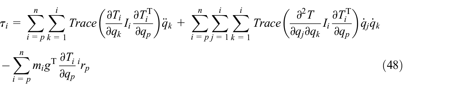
Inertia ratio of the serial manipulator
In this paper, the dynamic equation of PUMA560 manipulator is deduced by constructing a Lagrange energy function. The dynamic equation is written as Eq. (49).

here

According to the literature,22,23 the dynamic equation of the PUMA560 manipulator can be obtained, and then the mass matrix of the manipulator can be obtained. Figure 17 shows the variation rule of mass matrix elements with the rotation angle

The variation rule of mass matrix elements in the PUMA560 manipulator.
According to the literature,22,23 the rotary inertia of the motor value is

Diagram of the radius of the serial mechanism.
Influence of inertia ratio change on the serial manipulator servo drive system
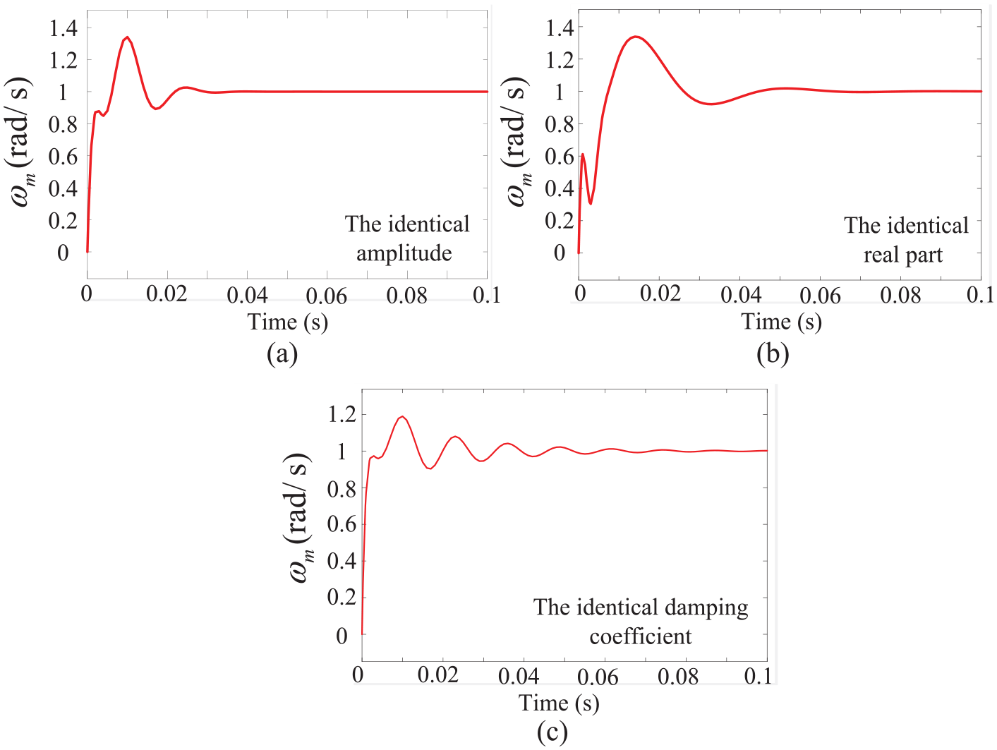
Due to the time-varying characteristics of the inertia of the serial mechanism, the inertia ratio of the servo system will change. To explore the influence of different inertia ratios on resonance magnitude of the system, the inertia ratios of the serial manipulator in three different locations are selected. The three special values are taken. Numerical simulations were performed using three-pole placement methods. The unit step signal is used as the input in the numerical simulation experiment, which indicates that the speed change process of the independent joint servo motor during startup. The system transfer function is shown in Eq. (6). The value of the transfer function is determined according to the specific locations of the PUMA560 robot. The PI control strategy is used to feedback control the system. The system output can be adjusted according to the value of the controller parameters, so that the system can get a stable output. The simulation results are shown in Figures 19–21.
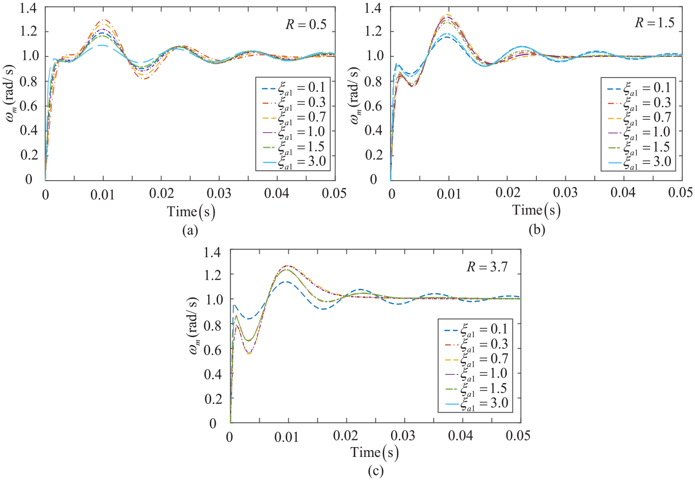
Simulation results of the pole assignment strategy with the identical radius in the serial manipulator.

Simulation results of pole assignment strategy with the identical damping coefficients in the serial manipulator.

Simulation results of pole assignment strategy with the identical real parts in the serial manipulator.
According to Figure 19, under the pole assignment strategy with an identical radius, on the interval of the damping coefficient of the pole from 0 to 1, with the damping coefficient increases, the system overshoot increases, the dynamic response characteristics deteriorate. On the interval of the damping coefficient from 1 to 3, with the increase of damping coefficient, the system overshoot decreases and the resonance magnitude decreases. According to Figure 18(a), when the value of the inertia ratio is too small, a certain degree of fluctuation will occur after the motor speed reaches the ideal speed. That is not conducive to the control of the serial manipulator servo drive system. Compared with the other two methods, the serial manipulator servo drive system adjustment time is shorter.
According to Figure 20, under the pole assignment strategy with the identical damping coefficients, on the interval of the damping coefficient of the pole from 0 to 1, with the damping coefficient increases, the system overshoot decrease. When the damping coefficient is small, a certain fluctuation will occur after the motor speed reaches the ideal speed. When the damping coefficient is 0.7, the damping coefficient has little influence on the system. Comparing with Figure 20, it can learn that as the inertia ratio increases, the fluctuation of the speed of the motor after reaching the ideal speed is weakened. The characteristics of the underdamped property gradually enhanced, which is especially obvious when the damping coefficient is small. The increase of the inertia ratio of the serial manipulator servo drive system increases the adjustment time. Compared with the other two methods, the system overshoot is larger.
According to Figure 21, under the pole assignment strategy with the identical real part, on the interval of the damping coefficient of the pole from 0 to 1, with the increase of damping coefficient, the system overshoot increases. When the damping coefficient is small, the serial manipulator servo drive system cannot achieve stability. Comparing with Figure 21, it can learn that when the damping coefficient is equal to 0.1, with the gradual increase of the inertia ratio of the system gradually tends to be uncontrollable. This shows the effect of the inertia ratio on the system. The system is unstable if the selected value of the damping coefficient is too small, which consistent with the absence of poles in Figure 15. It shows that this strategy has great limitations on the choice of damping coefficient compared to the other two methods.
Through the example of the PUMA560 manipulator, it can be found that the rotational inertia at the motor and the serial mechanism changes with the location of a serial manipulator. That causes the change of the inertia ratio of the two-mass system. This kind of change in the inertia ratio is more common in the serial manipulator servo drive system. By comparison, it can be found that the pole assignment strategy with the identical real parts and damping coefficients causes the system control to fail due to the change of the inertia ratio. Therefore, the influence of inertia ratio variation should be fully considered when designing PI controller parameters. The above example shows that the pole assignment strategy with the identical radius and damping coefficients is suitable for the situation where the inertia ratio varies greatly.
Effect of parameter uncertainties on the dynamic response of the control system
The inertia of the serial mechanism and the motor side shows obvious time-varying characteristics due to the positions transformation of the serial mechanism. The time-varying characteristics of the inertia make it difficult for the control serial manipulator servo drive system to obtain a stable output. This difficulty is mainly reflected in the strong robustness of the system. This is because the system dynamics parameters change greatly during the robot’s motion. In order to study the influence of time-varying characteristics of inertia on open-loop transfer function, this paper randomly selects 5 groups of inertia of the serial mechanism and the motor side for simulation experiments. The Bode diagram of open-loop transfer function and the speed output diagram of unit feedback under unit step input excitation are drawn respectively, as shown in Figures 22 and 23.
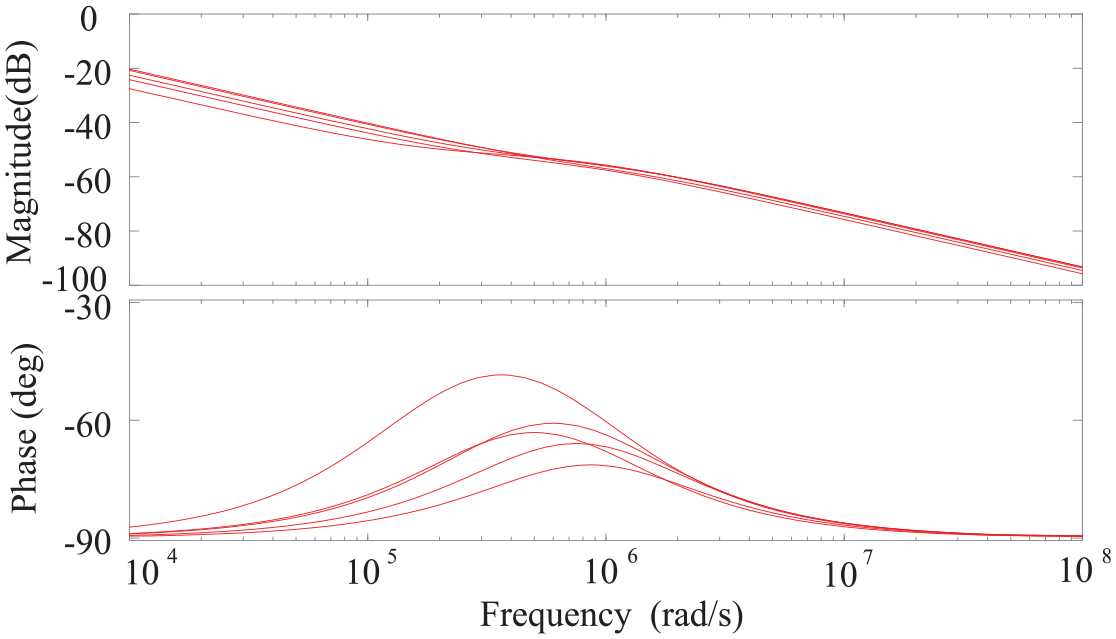
Bode diagram of open loop transfer function under variable parameters.

System unit step response curve under variable parameters.
According to Figure 22, when the serial manipulator servo drive system dynamics parameters change, the amplitude of the open-loop transfer function does not change much, but the phase changes significantly. According to Figure 23, although the change of dynamic parameters did not affect the final output value of the system, it changed the time when the system reached the stable state. This change in dynamic parameters will affect the robot’s motion accuracy. According to Figure 23, we can conclude that the system has strong robustness.
When the serial manipulator is in different positions, the inertia ratio will change. If the serial manipulator servo drive system controller is set to a single parameter, there is no guarantee that the system will obtain a stable speed output. In this paper, the same controller parameters are used to control the series manipulator in different positions. This change in inertia ratio will affect the dynamic response of the system. As shown in Figure 24, the change of inertia ratio will cause the change of dynamic response characteristics such as velocity fluctuation, adjustment time and maximum overshooting of the system. This kind of system output speed change is simulated under the unit step signal input, using the PI control strategy under the same control coefficient. Using the same controller parameters will cause the resonance and affect the stability of the system.

The system output under same controller parameters.
In order to obtain a stable speed output, the system controller parameters are adjusted to offset the speed fluctuations caused by the change of dynamic parameters. Change the controller parameters to control the system. As shown in Figure 25, under the unit step signal input, the serial manipulator can obtain a stable output under different positions.
The system output under variable controller parameters.
Design procedure for the variable parameters PI controller
This paper takes the movement processes of the PUMA560 manipulator as an example to illustrate the steps to suppress the robot’s jitter by adjusting the controller parameters, as shown in Figure 7. Firstly, according to the movement processes of the PUMA560 manipulator, it is divided into several positions, as shown in Table 2. Then the parameters such as the inertia of the motor and the serial mechanism of the PUMA560 manipulator are determined under different positions. Next, the appropriate controller parameter setting methods and the optimal natural frequency and damping coefficient of the poles are selected through the inertia ratio. Thus, the proportion and integral coefficients of PI controller under different positions conditions are determined. Finally, according to the time series of the PUMA560 manipulator movement, the controller is changed in order to achieve the best controller parameters.
The PUMA560 manipulator motion division processes.

According to Table 2, the motion is divided into three motion paths, corresponding to the working conditions of Position 1, Position 2 and Position 3 in Table 2, respectively. The parameters of the serial manipulator under different working conditions are respectively determined as shown in Table 3. When the serial manipulator is in Position 1, the mass of serial mechanism is large, so low rotation speed is adopted to obtain a large torque to drive the serial manipulator to rotate. According to the inertia ratio, the controller parameters design methods of the serial manipulator servo drive system is selected and the controller parameters are optimized by adjusting natural frequency and damping coefficient of the poles. Finally, the optimal controller parameters are obtained under each position condition.
Position parameters of the PUMA560 manipulator.
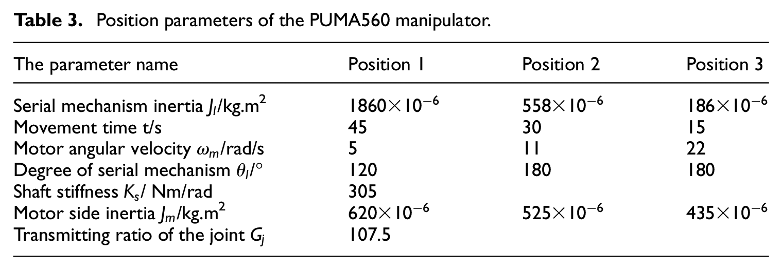
In this paper, the simulation experiment of the PUMA560 manipulator in continuous movement is carried out. First, the fixed controller parameters are selected for the experiment to obtain the motor output speed, as shown in Figure 26(a). Next, a variable parameter control strategy is used to carry out experiments to obtain the motor output speed, as shown in Figure 26(b). According to the comparison, under the operating conditions of Position 1 and Position 2, the variable parameter control strategy can reduce the fluctuation of motor output speed and achieve the purpose of vibration suppression.

The output speed of the PUMA560 manipulator.
Comparison with other methods
In order to verify the effectiveness of using a variable parameters PI control method based on pole assignment strategy to control serial manipulator servo drive system, this paper uses a robust control strategy and traditional PI controller parameters design method to carry out simulation experiments.
This paper compares PI control strategy with robust control to illustrate the effectiveness of PI control strategy. However, there are many methods to design PI controller parameters. In order to illustrate the advantages of the parameter setting method based on pole assignment strategy, this paper compares with the traditional controller design method to illustrate the advantages of using pole assignment strategy, to design the controller.
The general structure of the robust control system is shown in Figure 27(a). Where

The robust control structure.
From this, the expression of

here
The MATLAB toolbox can be used to solve the expression of


The equivalent system control structure.
To study the control effect of robust controller, the above parameters are used to control the speed of PUMA560 manipulator’s servo drive system, and the numerical simulation results are shown in Figure 29.
Simulation results under robust control strategy.
According to Figure 29, the robust control strategy can enable the serial manipulator servo drive system to obtain a stable speed output. However, the time-varying characteristics of the system’s rotational inertia, the time of the serial manipulator to reach the rated speed under different positions will be different. This situation will affect serial manipulator’s motion accuracy. In addition, the selection of the weighting function in the robust control strategy is also a difficulty in using robust control.
The PI controller parameters were determined using three pole assignment strategies and the traditional method——Ziegler-Nichols method. The values of the parameters are shown in Table 4. The above parameters are used to control the speed of PUMA560 manipulator’s servo drive system, and the numerical simulation results are shown in Figure 30.
Control system parameter.


Simulation results of different PI parameter setting methods.
According to Figure 30 comparing the pole assignment strategy with the traditional method, the time for the serial manipulator servo drive system to reach a stable state is shorter and the control effect is better. The traditional method takes too long to reach a stable state, which will affect the dynamic accuracy of the serial manipulator. Therefore, using real-time control strategies with variable controller parameters can improve the accuracy and stability of the serial manipulator servo drive system. In the three pole assignment strategies, the identical radius and damping coefficients methods should be preferred.
Conclusion
This paper established the dynamic model of the serial manipulator servo drive system and adopted the PI control strategy to control the system. The influence of the damping coefficient on the time domain characteristics of the serial manipulator servo drive system was discussed. The following conclusions could be drawn.
The method proposed in this paper to control the serial manipulator servo drive system used the PI control strategy. This control strategy could learn the relationship between the parameters of the PI controller and the zero-pole of the system. The speed fluctuation could be reduced by selecting PI controller parameters.
When applying the pole assignment strategies, first considered with the identical radius and the identical damping coefficient. These two strategies could adapt to the situation where the inertia ratio changes greatly, and the selection of the damping coefficient was not very strict. If the pole assignment strategy with the real part was chosen, the damping coefficient should be carefully selected. If the damping coefficient was too large or too small, the serial manipulator servo drive system could not reach a stable state.
It could be learned from the examples that the inertia of the motor and the serial mechanism was related to the location of the serial manipulator. The change of the inertia ratio should be considered when designing the PI controller parameters. The simulation results verified the effectiveness of the parameter setting methods.
Footnotes
Appendix
Nomenclature

| Motor side inertia | kgm2 | Reference speed | rad/s | ||
| Rotary inertia of the motor | kgm2 | Proportional gain | |||
|
|
Serial mechanism inertia | kgm2 |
|
Integral gain | |
|
|
Transmitting ratio of the joint |
|
Natural frequency of the pole | ||
|
|
Element in the inertia matrix | kgm2 |
|
Natural frequency of the pole | |
|
|
Motor electromagnetic torque | Nm |
|
Damping coefficient of the pole | |
|
|
Load-side torque | Nm |
|
Damping coefficient of the pole | |
|
|
Shaft stiffness | Nm/rad |
|
Link length | m |
|
|
Transmission system damping | Nms/rad |
|
Link twist | rad |
|
|
Motor side damping coefficient | Nms/rad |
|
Link offset | m |
|
|
Load side damping coefficient | Nms/rad |
|
Joint angle | rad |
|
|
Motor angular | rad |
|
Link transformation formula | |
|
|
Load angular | rad |
|
Inertia tensor matrix | |
|
|
Motor angular velocity | rad/s |
|
Generalized displacement of joint | rad |
|
|
Load angular velocity | rad/s |
|
Generalized force of the ith joint | |
|
|
Anti-resonance frequency, |
|
Inertia Matrix | ||
|
|
Resonance frequency |
|
Coriolis Matrix | ||
|
|
Inertia ratio |
|
Gravity Term |
Declaration of conflicting interests
The author(s) declared no potential conflicts of interest with respect to the research, authorship, and/or publication of this article.
Funding
The author(s) disclosed receipt of the following financial support for the research, authorship, and/or publication of this article: The authors greatly appreciate the financial support from the National Natural Science Foundation of China (Grant No. 51875092) and the Fundamental Research Funds for the Central Universities (N170302001).