
Abstract
Ship maneuvering in restricted waters is a significant challenge in navigation safety due to the complex flow around the ship. In particular, when a ship travels close to a lateral bank and shallow water, the hydrodynamic interaction forces significantly influence the maneuvering motion of the ship. Maneuverability in restricted water is even more difficult for an autonomous surface ship. Therefore, it is necessary to assess the effects of maneuvering near a bank and in shallow water for an autonomous surface ship. In this study, maneuvering simulations considering the bank effect at various water depths are implemented based on hydrodynamic forces estimated using computational fluid dynamics simulation. First, virtual captive model tests at various water depths and simulations of various lateral distances to the banks are performed to estimate the hydrodynamic forces using computational fluid dynamics simulation. The simulation method is validated by comparing the simulation results of the static drift test in deep water with the measured one in the experimental method. Second, the maneuvering simulations for the turning circle test and zig-zag test at various water depths are conducted using the obtained hydrodynamic coefficients. Then, the maneuvering simulations in deep water are compared with the experiment results, and a good agreement is observed. Finally, the simulation considering the bank effects at various water depths is evaluated and discussed.
Keywords
Introduction
Ships are designed not only for oceangoing transport, but also for moving in restricted water areas. The maneuverability of a ship is one of the essential characteristics of ship performance that allows a ship to operate safely and efficiently. However, the boundaries of a waterway significantly affect a ship's behavior. As the ship travels, the flow velocity through the gap between the ship's bottom and the seabed is increased, as is that between the side of the ship and the banks. When the ship travels in restricted water, there is a change of water pressure along the hull due to the seabed and vertical bank. The water level increases at the position of higher pressure, and it decreases at the position of lower pressure, thus causing sinkage and trim when the ship is in forwarding motion. Furthermore, the difference in pressures created a suction force directed from higher-pressure areas toward lower-pressure areas.
Research examining the influence of confined water as shallow water, particularly the bank effect, has been conducted in recent years. For example, Mucha 1 presented the maneuverability of the ship in deep and shallow water. A 6-degree of freedom (6-DOF) modular mathematical model and reference technique for estimating the maneuvering simulation were proposed by Taimuri et al. 2 in deep and shallow water. Besides, Amin and Kazuhiko 3 also suggested the empirical formula for the hull, propeller, and rudder interaction coefficients considering shallow water effects. Delefortrie et al. 4 introduced the 6-DOF mathematical maneuvering model in shallow water and the hydrodynamic coefficients were obtained based on the captive model test in towing tank. Yoshimura 5 and Yoshimura and Sakurai 6 applied the MMG (maneuvering modeling group) model that was developed for the mathematical model in deep water for the prediction of maneuvering motion in shallow water. It was confirmed that the MMG model was still available for maneuvering prediction in shallow water. Regarding bank effects interaction, Vantorre et al. 7 developed empirical formulae for estimating ship–bank interaction forces based on an experiment involving three ship models with varying water depths, lateral distances, forward speeds, and propeller rpm. To investigate realistic bank geometry, a series of model tests with different irregular bank geometries were conducted in a towing tank by Lataire and Vantorre 8 for predicting the forces, moments, and motion, a formula of the mathematical model was then established based on forward speed propulsion, the entire bank, and bottom geometry. The performances of ship–bank interaction in shallow water were experimentally investigated by Liu et al., 9 Sano et al., 10 and Kazerooni and Seif. 11 Applying the numerical computation method, Van Hoydonck et al. 12 conducted an experiment and compared it to computational fluid dynamics (CFD) code in shallow water with surface-piercing banks and a vertical quay wall. CFD simulations of ship–bank interaction were also done by Hong and Lee 13 and Ang et al. 14 A review of aspects of shallow water and bank effects were surveyed by Duarte et al. 15 from different standpoints. The definition of water level conditions was mentioned as follows deep water: h/T > 3.0, medium deep water: 1.5 < h/T < 3.0, shallow water: 1.2 < h.T < 1.5, and very shallow water: h/T < 1.2. Kobyliński 16 gave a physical explanation for ship–bank interaction based on Bernoulli's law: The water velocity increases at the space between the bank and ship, which leads to a difference in pressure on each of the ship sides, and it is directed from the higher pressure area to the lower pressure area; this is called suction force. On the other hand, the ship's bow is pushed away from the bank by yaw moment due to the increased pressure around the bow.
Studies on the maneuverability of twin-propeller and twin-rudder ship have been presented by researchers. Khanfir et al. 17 investigated the maneuvering characteristics of a ship with a twin-rudder system and applied it to propose the method for estimating the hull rudder interaction coefficient for different rudder systems (it can be single-propeller or twin-propeller) and the flow-straightening coefficients from free-running test Di Mascio et al. 18 used various prediction methods namely statistical regression, system identification, and RANSE (Reynold-Averaged Navier-Stoke Equation) to evaluate the maneuverability behavior. Sukas et al. 19 analyzed the influence of different methods such as single-run, multiple-run, and free-running model simulation on maneuverability. Of course, the mathematical model for the twin-propeller and twin-rudder ship was mentioned in those researches.
Applying CFD simulation on marine vehicles, highlight the maneuvering performance of the ship by Hajivand and Mousavizadegan, 20 Liu et al., 21 and Balagopalan et al., 22 and submerged body like Jeon et al., 23 and Cho et al. 24 was predicted from the virtual captive model test for estimating hydrodynamic coefficients. Then, the accuracy of CFD simulation was verified with the experimental method for demonstrating the effectiveness of the CFD method in predicting ship maneuverability.
From the literature review just presented, it is clear that former researchers have performed the ship's maneuverability in shallow water or simulated the bank effects in various water depths. However, they focused on the ship–bank interaction and changing hydrodynamic forces and moments when the ship is close to the lateral bank at various water depths without researching the maneuvering simulation close to the lateral bank. Good knowledge of the ship on the trajectory close to the lateral bank even though it is going on straightforward simulation is useful to predict the ship's attitude in the design stage. In this study, a maneuvering simulation considering bank effects at various water depths is carried out at low speed for an autonomous surface ship installed with twin propellers and twin rudders. A mathematical model for the hull considering bank effects is given. Virtual captive model tests are performed using the CFD numerical method to obtain hydrodynamic forces. To validate the CFD simulation method, the hydrodynamic force and moment of static drift test in deep water obtained from the simulation are compared with the measured one by the experimental method. Besides, the turning circle and the zig-zag tests, which use the hydrodynamic coefficients obtained from the CFD method are simulated and compared with those results using hydrodynamic coefficients obtained from the experimental method in deep water. Then, the straight simulation close to the lateral bank is evaluated at various lateral distances and water depths.
CFD-based modeling
Governing equation
The key to applying CFD for ship motion is the governing equations of fluid dynamics: the continuity equation and the momentum equation. These equations are mathematical statements of mass conservation, Newton's second law. With the assumption that the flow around the ship is incompressible, the governing equations are expressed as


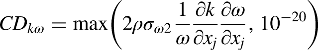
Turbulence model
In this study, the


Numerical modeling
The computation domain of the ship in restricted water is illustrated in Figure 1. According to the ITTC (International Towing Tank Conference, 26 recommendation on Practical Guidelines for Ship CFD Applications, the boundaries should be located 1.0–2.0Lpp away from the ship hull so that the inlet and outlet boundaries are, respectively, located 2Lpp upstream and 4Lpp downstream from midship. In addition, due to the different water depths and distances to banks, the bottom and one side boundaries are adjusted based on the test conditions. Meanwhile, the remaining side and top boundaries are, respectively, positioned 3Lpp from the center plane and 1Lpp from the water plane. Further, the physical conditions are applied for each boundary domain. The inlet and outlet faces are respectively assigned to the pressure inlet and the pressure outlet. The no-slip wall condition is specified for the hull surface, bottom, and vertical wall. The top face and remaining side face are considered to be symmetry conditions.

Boundary domain in restricted water.
Hybrid mesh is applied in this study. Because the unstructured mesh is flexible, which facilitates the mesh generation for complex geometry, the tetrahedral mesh is used to discretize the inner part, including the hull. The structured mesh is discretized for the outer part far from the hull to reduce the number of mesh elements. In addition, the boundary layer around the hull is generated using a prism mesh grown out of triangle mesh to resolve the flow surrounding the hull. On the other hand, the height of the first prism element next to the hull is calculated to satisfy the y + value of 300 corresponding to the transition flow regime at the Reynolds number of 3.4 × 10⁷ (Figure 2).

Mesh generation.
The RANS-based solver in ANSYS Fluent is used to simulate the fluid flow through the hull. The two-equation turbulence models
Mathematical model
Objective
An autonomous surface ship installed with twin propellers and rudders, which is shown in Figure 3(a), is introduced. However, within the scope of this article, only the full scale of a bare hull is used for simulation. Figure 3(b) depicts the bare hull of an autonomous surface ship (Table 1).

Autonomous surface ship. (a) Ship with twin propellers and twin rudders. (b) Bare hull geometry.
Parameter of the ship.

Equations of motion
Two right-hand coordinate systems are used to describe the 3 degree of freedom (3-DOF), as shown in Figure 4. The body-fixed coordinate system o-xbyb is adopted to measure the hydrodynamic force of the ship where o is located on the midship. The earth-fixed coordinate system O-xy is applied for a global position to define the ship trajectory of the ship.

Coordinate systems.
The MMG model proposed by Yasukawa and Yoshimura
27
is adopted for a maneuvering simulation of a ship. Yoshimura
5
also confirmed the MMG model's accuracy for predicting maneuvering motion in shallow water. The mathematical model for the 3-DOF equation of motion is expressed as shown in equation (6):
Hydrodynamic forces acting on the ship hull
This study investigates the hydrodynamic forces acting on the ship hull while considering the bank effect at various water depths. To characterize the hydrodynamic forces caused by the bank effect at different water depths, the lateral position of the ship is set as 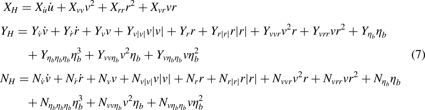

Parameters of restricted water.
The variables are transferred to non-dimensional values based on the ship length L, ship speed U, and water density ρ. They are distinguished by putting the sign of 
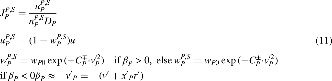
Hydrodynamic forces due to propeller
As introduced in section “Objective,” this ship uses twin rudders and twin propellers. Sukas et al.
19
described a mathematical model for twin propellers and twin rudders. The hydrodynamic forces due to the propeller are described as presented in equation (9):

Hydrodynamic forces due to rudder
The hydrodynamic forces on the ship due to the rudder are expressed as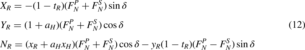


Here
Virtual captive model tests
The virtual captive model tests are conducted at various water depths using the CFD numerical method to obtain hydrodynamic coefficients. A simulation of various lateral distances to the banks is also conducted, and it obtains asymmetric coefficients and bank effects interaction. Due to the dangerous conditions of restricted water, low-speed conditions are selected for simulation. The test conditions of the virtual captive model tests and bank effects are described in Table 2.
Test matrix of the virtual captive model test at various water depths and bank effects.

Validation
To validate the simulation method, the non-dimensional sway force and yaw moment of static drift test in deep water obtained from the simulation are compared with the measured one by the experimental method given by Vo et al. 28 Figure 6 shows the results of validation for the simulation method. The simulation force and moment are found to be in fairly good agreement with the measured one. The average comparative differences between the simulation and experiment sway force and yaw moment are 1.56% and 7.05%, respectively. Therefore, the simulation method can be used in further study.

Validation of simulation method from static drift test in deep water.
Resistance test
The resistance test is the drag acting when the ship is moving straight at various speeds, and it is a function of the drag generated by the surge velocity. Figure 7 presents the total drag coefficient

Results of resistance test at various water depths.
Static drift test
In the static drift test, the ship moves in oblique flow due to a given drift angle

Results of static drift test at various water depths: (a) Surge force, (b) sway force, and (c) yaw moment.
Circular motion test
The hydrodynamic forces of the circular motion test (CMT) are a function of the yaw rate. Figure 9 shows the hydrodynamic forces of CMT at various water depths. A significant increase at h/T = 1.2 is observed at sway force and yaw moment. This indicates that shallow water also significantly influences hydrodynamic force versus yaw rate.

Results of circular motion test at various water depths: (a) surge force, (b) sway force, and (c) yaw moment.
Combined circular motion with drift
The combined circular motion with drift is performed to obtain coupling hydrodynamic coefficients generated by yaw rate and yaw rate. According to this test, Figure 10 plots the hydrodynamic forces and moments by varying both drift angles and yaw rates at various water depths. As the water depth decreases, drift angle and yaw rate increase, and the hydrodynamic forces and moments increase as well.

Results of combined circular motion with drift at various water depths: (a) deep water, (b) h/T = 2.0, (c) h/T = 1.5, and (d) h/T = 1.2.
Bank effect
The bank effect is tested to obtain suction forces due to the lateral bank. The hydrodynamic forces can be obtained by gradually changing the distance to be increasingly farther from the bank. This is because counterflow is created between the bank and ship, so the pressures on both sides of the ship are different, and the velocity on the side close to the bank is larger than that on the other side. Therefore, sway force and yaw moment are created even though the ship is moving straight. Figure 11 depicts the hydrodynamic forces as the ship gets increasingly close to a bank at various water depths. It is a function of hydrodynamic forces with respect to the lateral distance from the bank to the center of the ship. The non-dimensional distance

Results of bank effect at various water depths: (a) sway force and (b) yaw moment.
Combined bank effect with drift
A combined bank effect with a drift test is conducted to obtain the coupled hydrodynamic forces concerning lateral distance and sway velocity. Figure 12 shows the sway force and yaw moment of the combined bank effect with drift angle at various water depths. Due to the impact of the lateral bank, the hydrodynamic forces caused by drift angles are asymmetrical over the center. This force is even larger when the ship is closer to the lateral bank and when the ship moves into shallower water.

Results of combined bank effect with drift at different water depths: (a) deep water, (b) h/T = 2.0, (c) h/T = 1.5, and (d) h/T = 1.2.
Figure 13 shows the velocity fields of the ship at various water depths. It demonstrates the increase in flow velocity through the gap between the ship bottom and the seabed as the water depth becomes shallower. Figures 14 and 15 present the velocity and pressure fields of the ship's proximity to the bank at various water depths. It can be seen that the velocity on the side close to the lateral bank is greater than that on the free side. This can be seen particularly clearly in the cases of η = 0.7B, especially h/T = 1.2, where the velocity on the side close to the bank is greater than the ship's velocity by about 1.5 times. The increased flow velocity and decrease in pressure through the gap between the ship bottom and the seabed when the water depth becomes shallower, and the port side and the lateral bank when the ship is close to the lateral bank are the cause of increasing hydrodynamic forces and moments. Moreover, the longitudinal wave cuts on the side close to the lateral bank (y/B = 0.6 m) and the free side (y/B = −0.6 m) are shown in Figure 16. This also proves the effect of lateral bank and shallow water: Because of the interaction between bow wave systems, a deep wave trough appears, which becomes deeper and moves astern as the ship moves close to the lateral bank. On the free side, the deep wave trough is almost similar at various lateral distances to the bank. Moreover, the deep wave trough deepens as the ship becomes shallower; this is observed on both sides of the ship.

Velocity field of the ship at various water depths (front view).

Velocity field of the ship proximity to the bank at various water depths (top view).

Pressure field of the ship proximity to the bank and various water depths (ηb = 0.7B).

Comparison of longitudinal wave-cut at different sides: (a) y = 0.6 m and (b) y = −0.6 m.
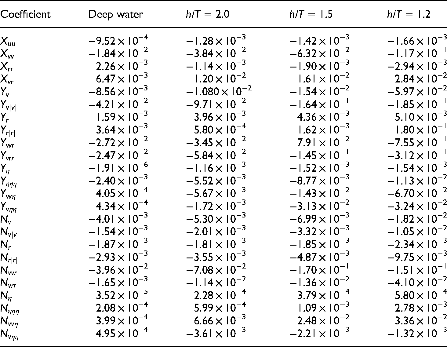
The hydrodynamic coefficients can be obtained by regressing the hydrodynamic forces and moments using the least-squares method of each test with respect to variables. Table 3 lists the hydrodynamic coefficients at various water depths. Because of the increasing hydrodynamic forces as the ship becomes shallower, the hydrodynamic coefficients also increase when the ship gradually moves into shallower water.
Hydrodynamic coefficients.
Maneuvering simulation
By using the estimated hydrodynamic coefficients, the maneuvering simulation is then conducted for turning and zig-zag standard maneuvers. The added mass coefficients of the hull model as

Comparison of maneuvering simulation in deep water: (a) turning circle and (b) zigzag 10o/10o.
Figure 18 displays the results of the maneuvering simulation of the ship when the ship goes straight near a lateral bank. The ship tends to move far away from the bank due to the suction force; however, this occurs slowly in deep water and faster in the case of shallow water. The turning rate is reduced as the ship is farther from the bank and seabed. Further, the ship can keep a straight path in deep water at

Ship trajectories nearby the bank.
Conclusion
This study focused on the bank-effects interaction at various water depths of an Autonomous Surface Ship. Because this ship has twin propellers and twin rudders, a maneuvering simulation is performed by referring to the mathematical models. The present study also provides a mathematical model of the ship considering bank effects.
Virtual captive model tests are implemented using a CFD numerical method to estimate the hydrodynamic coefficients. The accuracy of the CFD method is validated by comparing the simulation results with experiment one in the static drift test in deep water. The good agreement between the CFD method and the experiment results demonstrates that the CFD method can be used to predict the hydrodynamic forces of the ship. Besides, the turning and zig-zag standard maneuvers also are performed to ensure precisely the mathematical model and maneuvering simulation method.
To investigate the bank effects at various water depths, simulations of the ship close to the bank, considering shallow water, are conducted by giving various distances from the lateral bank to the ship's center. Moreover, a combined test between the lateral distance and the drift angle is performed. Consequently, the hydrodynamic coefficients relative to the bank effect are obtained for various water depths. The straight simulation near the bank is then implemented at various lateral distances and water depths. As a result, the straight path is not only affected by the lateral bank but also by shallow water conditions. Further, the velocity and pressure fields of the ship near the bank are observed at various water depths. The results described that the velocity and pressure on the side close to the lateral bank are greater than those on the free side. It indicates that the increased flow velocity and decrease in pressure through the gap between the ship bottom and the seabed when the water depth becomes shallower and the port side and the lateral bank when the ship is close to the lateral bank cause increasing hydrodynamic forces and moments. In addition, the longitudinal wave cut gave a deep wave trough, and this again demonstrated the influence of the lateral bank and shallow water on the ship dynamics.
This study aims to estimate the maneuvering simulation of a ship in restricted water in the design stage. An automatic control system will be calculated and reasonably designed to ensure navigation safety.
Footnotes
Acknowledgments
This research was supported by the ‘Development of Autonomous Ship Technology (PJT201313, Development of Autonomous Navigation System with Intelligent Route Planning Function)’ funded by the Ministry of Oceans and Fisheries (MOF, Korea).
Declaration of conflicting interests
The author(s) declared no potential conflicts of interest with respect to the research, authorship, and/or publication of this article.
Funding
The author(s) disclosed receipt of the following financial support for the research, authorship, and/or publication of this article: This research was supported by the “Development of Autonomous Ship Technology (PJT201313, Development of Autonomous Navigation System with Intelligent Route Planning Function)” funded by the Ministry of Oceans and Fisheries (MOF, Korea).
Author biographies
Thi Loan Mai is a PhD candidate student in the department of Smart Environmental Energy Engineering in Changwon National Univerisity, Korea. She got bachelor degrees in the department of Naval Architecture in Ho Chi Minh city University of Transport, Viet Nam in 2017. She got master degrees in the Department of Eco-friendly Offshore Plant FEED Engineering in Changwon National University, Korea in 2019. Her main interests are CFD simulation, seakeeping and maneuvering of marine vehicles.
Myungjun Jeon is a researcher in Changwon National University, Korea. He got bachelor, master, and PhD degrees in the Department of Naval Architecture and Marine Engineering, Changwon National University in 2015, 2017, and 2022. His main interests are modeling and simulation of marine vehicles.
Anh Khoa Vo is a PhD candidate student in the Department of Smart Environmental Energy Engineering in Changwon National University, Korea. He got bachelor degrees in the faculty of transportation mechanical engineering in Da Nang University of Technology, Viet Nam in 2019. He got master degrees in the department of Smart Environmental Energy Engineering in Changwon National University, Korea in 2022. His main interests are modeling and simulation of marine vehicle.
Hyeon Kyu Yoon is a professor in the Department of Naval Architecture and Marine Engineering in Changwon National University, Korea, He got bachelor, master and PhD degrees in the Department of Naval Architecture and Ocean Engineering in Seoul National University, Korea in 1989, 1991, and 2003. He worked for Agency for Defence Development from 1991 to 1996, and worked for Maritime Ocean Engineering and Research Institute from 2003 to 2009. His main interests are the simulation of marine vehicles such as a ship and underwater vehicles and the model test in the water tank.