
Abstract
To investigate the performance of engine cooling water pump in automobile with variable rotating speed, experimental tests and numerical simulation are carried out on an engine cooling water pump under the rotating speed of 2650, 2960, 3700, and 4300 r/min. The hydraulic performance under 3700 r/min rotating speed and the cavitation performance under 340 L/min flow rate are tested and analyzed. The predicted results agree well with the experimental results, indicating that the simulation has high accuracy. The results show that the head of engine cooling water pump increases gradually and the best-effective region moves toward high flow rate condition with the increase in rotating speed. The augment of rotating speed would deteriorate the internal flow fields and causes more energy losses, which is due to the increase in tip leakage flow and enhancement of rotor–stator interaction effects. And, the rotor–stator interaction effect is sensitive to the temperature under various rotating speeds. Furthermore, the required net positive suction head increases with the increase in rotational speed and anti-cavitation performance is weakened during cavitation conditions.
Introduction
With the requirement for improving the engine performance and reliability, the influence of the cooling system plays a more important role in the heat transfer for the cooling system, which becomes the research concentration of most scholars.1,2 Engine cooling water pump (ECWP) is the main component for conveying cooling water in the closed circulating cooling system of automobile engine. Not only can ECWP affect the power and economic of automobile but also decide the life span of the whole cooling water system. Therefore, the improvement of ECWP performance and quality is one of the most critical factors to reduce the energy losses and improve the efficiency.
Compared with conventional centrifugal pumps,3–7 ECWP works under higher temperature which may lead to serious cavitation performance, noise, vibration, and negative effect on the life span of cooling system.8–13 Therefore, lots of researches tried their best to improve the energy characteristics and cavitation performance of ECWP under high temperature. Yao et al. 14 simulated the cavitation performance of an airfoil and an ultra-small pump based on Kubota cavitation model. The results shown that the thermodynamic effects have significant impacts on the cavitation of pump in high temperature water, and it will suppress the pump cavitation to some extent. The durability test of the automobile water pump was studied by Junjie et al., 15 and they found that a pressure loss occurred between the impeller rear cover and the mechanical seal under high-temperature and high-speed conditions, which caused insufficient water seal flow at the rubber parts and generated cavitation. Furthermore, the cavitation characteristics of ECWP were also analyzed by Li and colleagues,16,17 and the Zwart–Gerber–Belamri cavitation model was employed to optimize the internal structure of ECWP combining with the computational fluid dynamics (CFD) technology.18–21 Finally, the blade inlet angle, blade wrap angle, and blade outlet angle of pump impeller were changed to deduce the energy losses in impeller channels, and the efficiency has been improved. Cipollone and colleagues22,23 designed a sliding vane rotary pump for an existing engine cooling circuit. They studied the cooling circuit modeling of new pump compared with traditional centrifugal pump and found advantages of new pump. Huang et al. 24 studied the effects of the percentage of anti-freeze in ECWP, and they found the engines have a higher tolerance to air bubbles at lower rates of rotation. Shi et al. 25 and Liu et al. 26 tried to improve the efficiency of automobile pump by changing the structure of pump as well, and they verified the pump performance by simulation. But, the relationship between pump efficiency and cavitation was still unknown. Actually, the cavitation characteristics of ECWP have relationships with the influences of rotation speed, flow rate, and other factors. Therefore, Liao and Xie 27 analyzed those factors and their effects on the cavitation performance of ECWP. In our previous study, 28 the blade outlet width of ECWP was investigated to improve the cavitation performance, but the cavitation performance became worse at best efficiency point (BEP) even though the improvement of head was found, whereas most of those literatures are concerned on the cavitation characteristics under the rated rotating speed. But as we know, when the automobile is moving on the road, its speed is not always the same; thus, the cooling system is no need to work at the rated rotating speed all the time as a result of saving energy. Consequently, the rotating speed of ECWP changes frequently during operation to match the speed of automobile or the requirement of thermal equilibrium of engine.
But until now, there are little literatures about the cavitation performance of ECWP under variable speed within high temperature. Zhang et al. 29 studied the ECWP under different rotating speeds by simulation and experiment, and the results show that the highest efficiency point will offset to large flow rate condition and the range of high efficiency has improved. But, due to the lower development of CFD at that time, the simulation is conducted at the room temperature. They just compared the external characteristics of simulation and experiment under room temperature and the cavitation performance of ECWP are not analyzed. Therefore, based on the advanced CFD technology at this time, it is necessary to investigate the cavitation performance of ECWP under high temperature and different rotating speeds. For the ECWP, as it is a kind of centrifugal pump, some findings of the centrifugal pump under various rotating speeds could be studied and applied to some extent. Up to now, some literatures have been found. Sha and colleagues30–32 investigated the axial pumps and swirl pumps under different speeds, and they built the relationship between the energy performance parameters and the internal flow field, which provides some references for optimizing the structure of pump. Moreover, the internal flow fields of a centrifugal pump under various speed were measured by the particle image velocimetry (PIV) technology, 33 and the pressure fluctuation of a single suction centrifugal pump at the tongue corner under variable speed was experimentally measured. 34 However, those findings are all conducted under the room temperature. At a higher temperature, the characteristic of fluid medium may change a lot and thus it is meaningful to do some researches on the cavitation performance and internal flow of an ECWP under various rotating speeds and high temperature.
In this work, the energy characteristics, cavitation performance, and internal flow fields of ECWP with four different speeds under room and higher temperature are studied based on CFD. According to the comparison results between CFD and experiment, the applicability of similar law for energy and cavitation performance of ECWP with variable speed was analyzed. This work provides a theoretical reference for the performance optimization and cavitation prevention of ECWP.
Numerical simulation
Research model
The performance and basic geometric parameters of ECWP discussed in this study are shown in Table 1. The working medium is water with designed temperature 80°C ± 2°C. The designed flow rate, head, and rotating speed are 340 L/min, 15 m, and 3700 r/min, separately. Considering the spatial limitation of chamber structure, manufacturing process, and requirements of engine, the blade of ECWP is designed wider than that of conventional centrifugal pumps. The designed two-dimensional structure of ECWP is shown in Figure 1(a). The assembled structure of ECWP is described in detail and the main components are shown as well. It is clear that the main components of ECWP are semi-open suction chamber, impeller, and volute. And then, the Unigraphics NX software is adopted to model the three-dimensional structure of main part of ECWP, which is shown in Figure 1(b). After the solid structures of ECWP have been finished, the simulation domain of ECWP should be extracted from them. But, in order to conduct the simulation better, the whole simulation domain has been divided into five single domains. Figure 2 shows the main simulation domain components of ECWP. It could be seen that the whole domain consists of suction chamber domain, impeller domain, tip cavity domain, volute domain, and outlet of volute domain. In particular, the structure of volute is relatively complex, so it is divided into two computational fields to conduct the mesh generation. Furthermore, each separated domain could be connected by the interface and then they could be assembled.
Impeller parameters of the investigated ECWP.

ECWP: engine cooling water pump.

Structure of ECWP: (a) 2D sketch of ECWP and (b) 3D sketch of ECWP.

The domain of investigated ECWP.
Mesh generation and independence analysis
The fluid domain for simulation is composed of five parts, so the mesh generation is conducted separately. Based on the ANSYS ICEM software, the hexahedral mesh is selected to discretize each simulation domain. Especially, the periodic topology is applied in the mesh generation of impeller domain because of its periodic structure. Meanwhile, the mesh near the impeller blade inlet and the volute tongue is refined as the flow at these regions is more complicated. Also, the mesh near the walls should be properly sized to ensure the resolution of the flow details. The desired target value of dimensionless parameter y+ has been imposed to control the first mesh cell. The maximum value of y+ is below 100. The mesh configuration of whole flow field is shown in Figure 3(a) and the mesh refinement of impeller and volute is shown in Figure 3(b) and (c).

Sketch of whole flow field mesh and the refined mesh of blade inlet and volute tongue: mesh generation of (a) whole domain, (b) impeller domain, and (c) volute domain.
In accordance with the volume of physical model and calculation accuracy requirement, the mesh density has been changed by adjusting the number of mesh nodes of impeller. The mesh independence test under the rated flow rate condition has been conducted later, which is shown in Table 2. A slight difference occurs in the pump head and efficiency, according to the results of simulation under four mesh densities. Theoretically, the deviation decreases progressively with the increase in mesh number because of its profound influence on calculating accuracy. Therefore, mesh D with 2,711,424 elements is employed for the following calculation and the change of head is less than 1% under this kind of mesh generation, which indicates the convergence of mesh. The mesh elements and minimum orthogonal angle of different components after selection are also shown in Table 3. It could be seen that all the mesh quality meets the requirement of simulation.
Mesh independence test under the rated flow rate.

Mesh information of different components.

Selection of turbulence model and cavitation model
Due to the extremely high Reynolds number in pump, the flow is turbulent and so a suitable turbulence model is necessary for the simulation. According to our previous researches,35,36 the k–ε turbulence model has more advantages in predicting the energy performance characteristics of ECWP than any other Reynolds-averaged Navier–Stokes (RANS) models. Also, it is equipped with the outstanding features of robustness and timesaver; thus, the k–ε turbulence model is selected to simulate the external characteristics and internal flow fields of ECWP under various rotating speeds. From the equation of k–ε turbulence model, it is clear that the eddy viscosity coefficient, turbulent kinetic energy, and turbulent kinetic energy dissipation are taken into account. The governing equations of k–ε turbulence model are as follows


where Pt is the turbulent kinetic energy generation term; μt is the turbulent viscosity coefficient; k is the turbulent kinetic energy (m2/s2); ε is the turbulent dissipation rate; Cε1= 1.44, Cε2= 1.92, σε= 1.3, σk= 1.0, Cμ= 0.09; Cμ is the empirical coefficient.
Furthermore, after the confirmation of turbulence model, the cavitation model is another key factor to conduct the calculation of internal flow fields and external characteristics. Due to the consideration of high-temperature flow medium and the better description for the transformation between vapor phase and liquid phase, in this study, the Zwart–Gerber–Belamri cavitation model was included in the transport equation model to solve the internal flow fields synchronously. For the Zwart–Gerber–Belamri cavitation model, the phase mass per unit volume transmission rate and void volume change rate are defined as follows


where F is an empirical coefficient, RB represents the bubble radius, rnuc= 5 × 10⁻⁴, rg= 1 × 10⁻⁶, pv is the vaporization pressure, p is the pressure of the liquid around the bubble, and VB is the bubble volume.
The continuity equation for the mixture is


where
The momentum equation for the mixture can be obtained by summing the individual momentum equations for all phases. It can be expressed as
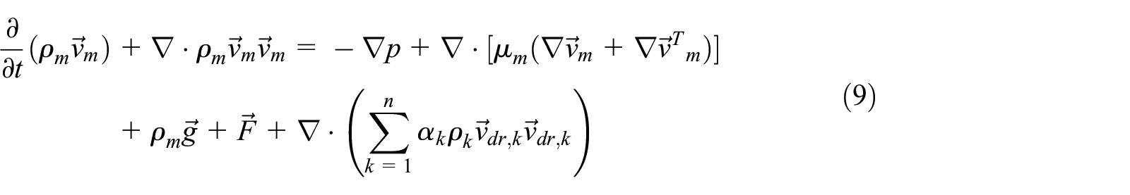


where n is the number of phases,
In cavitation model, the liquid-vapor mass transfer is governed by the vapor transport equation

where
Boundary conditions and simulation strategies
The commercial software ANSYS CFX 18.0 has been used to conduct the simulation of ECWP. The semi-open suction chamber domain and volute domain of ECWP are set in stationary reference frame, while impeller is situated in rotating reference frame. The problem of data transmission between stationary and the rotating domains is solved by adopting steady-state multi-reference system. The interface between the stationary reference frame and the rotating reference frame is set as frozen rotor. The specified pitch angles are set as 360° and general grid interface (GGI) model is chosen to process data transmission on the interface that guarantees the velocity continuity between the stationary and the rotating domains.
When doing the cavitation simulation, the non-cavitation flow is simulated first and then the cavitation simulation is conducted based on the initial value of non-cavitation results. The average cavitation bubble diameter is set as 2 × 10⁻⁶ m, and the saturated vapor pressure is 3.574 kPa at 25°C and 47.415 kPa at 80°C. Total pressure was set as the inlet boundary condition and the reference pressure was selected at a high level, and then the occurrence of cavitation is controlled by reducing the total pressure value at pump inlet. The outlet boundary is set as mass flow rate. Along with the decrease in inlet pressure, cavitation is aggravated in centrifugal pump and that leads to the decrease in every hydraulic performance parameter. The standard wall function is chosen in the domain near the wall with the roughness of 12.5 μm and the wall no-slip boundary condition is set as adiabatic wall. The volume fraction of water and bubble at inlet is set as 1 and 0, respectively. The second-order upwind scheme finite volume method is used to discretize governing equations, and then the pressure and velocity coupling method algorithm are adopted to solve the equations. To make sure of the accuracy, convergence objective for the residual is set as 10−4.
Experimental verification
Experimental equipment and methods
The closed performance experimental bed of ECWP is set up to verify the accuracy of numerical simulation, which is shown in Figure 4. The experiment is conducted later, and the model pump is matched strictly with the computational model (Figure 5). The test bed contains pressure gauge, pneumatic control valve, turbine flowmeter, temperature transmitter, torque sensor, frequency converter, and computer control system, and so on. The temperature transmitter is installed in the water tank to measure the system temperature. The main technical parameters of experiment bed are as follows: rotational speed, n≤ 8000 r/min; water temperature, T≤ 120°C; flow rate, Q≤ 400 L/min. The pump head is acquired by tow pressure gauge installed in the pump inlet and pump outlet, and the deviation of measurement is less than 0.15%. The pressure gauge at inlet has the range of pressure from 0 to 300 kPa and the pressure gauge at outlet has the range of pressure from 0 to 500 kPa. The flow rate condition is tested by the turbine flowmeter (LWGY-T/I) which is produced by Hefei Jingda Instrument Co. Ltd. The measurement accuracy grade of the turbine flowmeter is 0.2. The pump torque and rotating speed of pump are measured by a torque speed sensor which has a measurement range from 0 to 50 N m, and its measurement accuracy grade of the torque speed sensor is 0.5. The temperature of flow medium is controlled by PID (proportional–integral–derivative) system according to the feedback of temperature transmitter. The pneumatic control valve produced by Shanghai Star Co. Ltd (ZJHP-16KP) is chosen to adjust the valve opening of inlet and outlet pump. All the experimental procedures meet the requirements of national experimental standard (GB 3216-89, GB 1882-80, and QCT288.2-2001). The comprehensive error of the whole experimental system is ±0.5% through an uncertainty analysis of the system.

Closed experiment rig of ECWP.
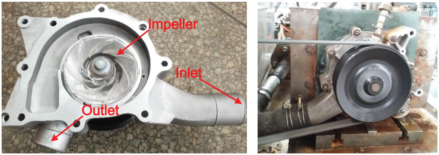
Pump model for experiment.
The external characteristics experiment and cavitation experiment are performed according to the requirements of reference. 37 In order to draw the hydraulic performance curves, the outlet flow rate is adjusted to change the operating condition. In the cavitation experiment, the flow rate is kept at the Q-BEP (340 L/min) and the inlet pressure is reduced slowly by adjusting valve resistance, to stimulate the cavitation inception in the cavitation experiment.
In the pump performance experiment, net positive suction head (NPSH) is a key parameter to evaluate the cavitation performance of pump. Moreover, the available net positive suction head (NPSHa) margin is always taken as the required net positive suction head (NPSHr) margin when the head declines about 3%. In this study, the NPSHa and NPSH have the same value because the install height of pump is not considered. The NPSH equation could be defined as follows

where ps is the total pressure of pump inlet (Pa), pv is the vaporization pressure for liquid (Pa), vs is the absolute velocity at inlet (m/s), ρ is the destiny of water (ρ = 1000 kg/m3).
Since the ECWP is driven by pulley provided with transmission ratio, the rotational speed is measured indirectly by the following formula

where n is the rotational speed of ECWP, nmotor is the motor speed measured by sensor, i is the transmission ratio.
Experimental results and verification
In simulation, many factors would affect the prediction accuracy of hydraulic performance during calculation. In this study, four factors are summarized as follows: (1) model simplification that neglects the volumetric loss, (2) efficiency difference between experiment and simulation, (3) model with casting defects, and (4) the effect of temperature on condensation evaporation coefficient and maximum density ratio is neglected. Those factors would make much deviation between simulation and experiment; thus, it is necessary to do something to verify the simulation results with experimental results.
In order to evaluate the external characteristics of model pump, the hydraulic performance experiment was carried out with 3700 r/min rotational speed at 25°C without cavitation. The comparison between simulation results and experimental results is shown in Figure 6(a). It can be seen from the hydraulic performance, the efficiency and head of numerical simulation are slightly higher than that of experiment. Particularly, the simulated pump efficiency is about 3.8% higher than the experimental data and the head is about 0.5 m higher than the tested head at BEP. For the cavitation performance, the test is conducted when the flow rate, rotational speed, and temperature are 340 L/min, 3700 r/min, and 80°C ± 2°C, respectively. The comparison between simulation results and experimental results is shown in Figure 6(b). It can be seen from the results that the NPSH of simulation is almost 4.5 m, which is 0.2 m higher than that of experimental result, but it is acceptable in error of simulation.
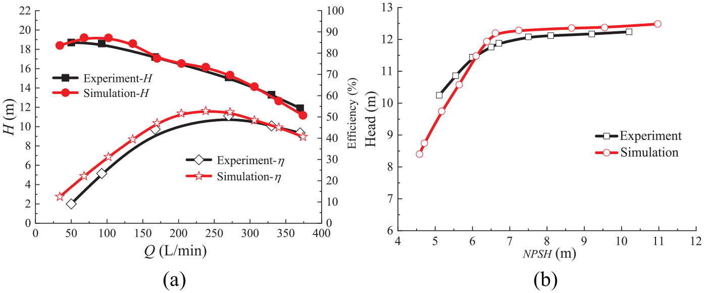
Comparison with hydraulic performance and cavitation performance: comparison of (a) hydraulic performance and (b) cavitation performance.
Generally, numerical simulation results are consistent with experimental results for both hydraulic and cavitation performance to some extent, which indicates the high reliability of numerical simulation. Besides, it is verified that the numerical simulation, for adopting hexahedral mesh and k–ε turbulence model, is the effective method to predict the hydraulic and cavitation performance of ECWP.
Results and discussion
Hydraulic performance under various rotating speeds
In this section, the hydraulic performance of ECWP with four different rotational speeds (2650, 2960, 3700, and 4300 r/min) is numerically predicted. The head and efficiency are shown in Figure 7. It can be found that with the increase in speed, the pump head increases slowly and BEP offsets to large flow rate conditions. In addition, the high efficiency region of ECWP decreases significantly under low-speed conditions, while it shows better performance under high-speed conditions. As shown in η-Q curve, the slope of curve decreases with the increase in speed when the flow rate is smaller than 160 L/min, but it shows the opposite feature when the flow rate is larger than 200 L/min.

Hydraulic performance with different speeds.
In fact, during the design procedure of centrifugal pump, the similar law is always employed to conduct the blade hydraulic design. Tian et al. 38 tested centrifugal pumps and corrected the similar law with different specific speeds. Thus, based on that law, the hydraulic performance of ECWP under different rotating speeds could be compared under the same criteria. The similar law demonstrated as formulas (15) and (16) indicates the relations between parameters with the change of speed, which is widely applied in design and experiment


where Q is volume flow rate (m3/s), H is head (m), n is rotational speed (r/min).
Furthermore, the application of similar law on the ECWP is also verified by the comparison of hydraulic performance. The H-Q curve of ECWP under the speed of 2650, 2960, and 4300 r/min is all transformed and compared with the H-Q curve under the rotating speed of 3700 r/min. The result illustrated in Figure 8 shows that the head of transformed curve under the same flow rate conditions is nearly constant with the one under the rated rotating speed and the maximum deviation of head is below 5%. Therefore, head similar law is applicable for variation of speed involved in the current model.

Transformed head flow curve.
Internal flow under various rotating speeds
Figure 9 shows the internal flow fields of pump at rated flow rate condition with four different rotating speeds. The monitor section is located at the middle of impeller and is perpendicular to the rotation axis. It can be found that the flow velocity in impeller flow channel becomes bigger with the increase in rotating speed. Near the tongue of volute, the streamline and vector of fluid is smooth, but it changes to be disordered at the opposite side of tongue, especially in the flow channels of P3, P4, and P5. However, the disordered region shrinks with the augment of rotating speed. Except for the flow fields in impeller, the flow is much more different at the outlet of impeller and volute. With the increase in rotating speed, the most obvious change is also the velocity magnitude at outlet of volute, which is caused by the increase in circumferential velocity at the outlet of impeller. The change of the circumferential velocity impacts the outflow angle of fluid from impeller. Under various rotating speeds, due to the large flow angle between the outflow direction and the wall of volute tongue, an intensive vortex (A) is formed and extends from the tongue to the middle section of volute outlet. With the increase in rotating speed, the intensity of vortex A decreases slight. Furthermore, vortex A changes a lot because the back-flow vortex B forms at the further outlet of impeller. Vortex A is squeezed by Vortex B and both of their intensity and area become smaller. Conclusively, in order to improve the flow rate condition and head of pump, the increase in rotational speed will lead to the deterioration of flow fields of pump outlet. Therefore, the rotating speed of pump could be limited within a reasonable range.
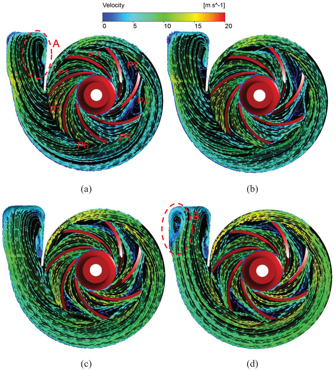
Internal streamline on middle section with various rotating speeds: (a) 2650 r/min, (b) 2960 r/min, (c) 3700 r/min, and (d) 4300 r/min.
Figure 10 demonstrates the effect of impeller rotating speed on the internal turbulence kinetic energy. Likewise, the monitor section is the middle plane of impeller. It gives more details of the flow fields under various rotating speeds. It can be seen from Figure 10 that the vortex dissipation in the impeller has an important part of energy losses which causes high turbulence kinetic energy and then affects the pump efficiency. The high turbulence kinetic energy regions appear at the impeller outlet, tongue of volute, and in the volute where vortexes could form easily. Under various rotating speeds, the turbulence kinetic energy is non-uniform at different flow channels and its value is relatively lower near the hub of impeller inlet. When the pump operates at low rotating speed, the regions at volute tongue and the corner in volute near the tongue cause more energy losses. But, the value of turbulence kinetic energy is low because of the lower flow velocity. When the pump operates at high rotating speed, the high-energy loss regions come up at the impeller outlet and in volute. For instance, at speed of 4300 and 3700 r/min, a highly turbulence kinetic energy region shows up in the flow channel of P4, P5, P6 and they are on the way approaching volute tongue. In general, the total turbulence kinetic energy in impeller increases with the increase in rotating speed, and the flow fields in the flow channels near the volute tongue are more turbulent than others. That is to say, it is not advisable for the ECWP working at too low or too higher rotating speed.

Distribution of turbulence kinetic energy on a middle section with various rotating speeds: (a) 2650 r/min, (b) 2960 r/min, (c) 3700 r/min, and (d) 4300 r/min.
In fact, the structure of impeller is semi-opened, so the flow fields from hub to shroud are not uniform for the existence of small gap near shroud. The distribution of turbulence kinetic energy at different flow sections from hub to shroud under various rotating speeds is shown in Figure 11. The three sections are separately at the impeller inlet, impeller middle, and impeller outlet and the diagram of these sections is shown in Figure 12. It is clear that the turbulence kinetic energy value near the shroud is higher than that near the hub which is a strong reason for the impact by the tip leakage flow. At the impeller inlet, the level of turbulence kinetic energy is low at low rotating speed, but it increases sharply when the speed reaches 4300 r/min. At the middle section and outlet section, the turbulence kinetic energy in these sections shows the same trend under low speed. However, the value of turbulence kinetic energy becomes larger at the flow channel of P6 and P7 than that of any other flow channels under high rotating speed, which means that the effect of rotor–stator interaction between impeller and volute is relatively high and the augment of rotating speed would aggravate this impact.
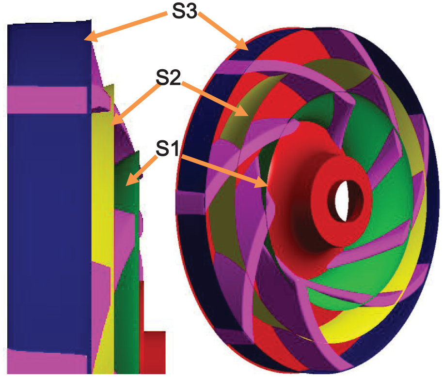
Diagram of monitor section position.
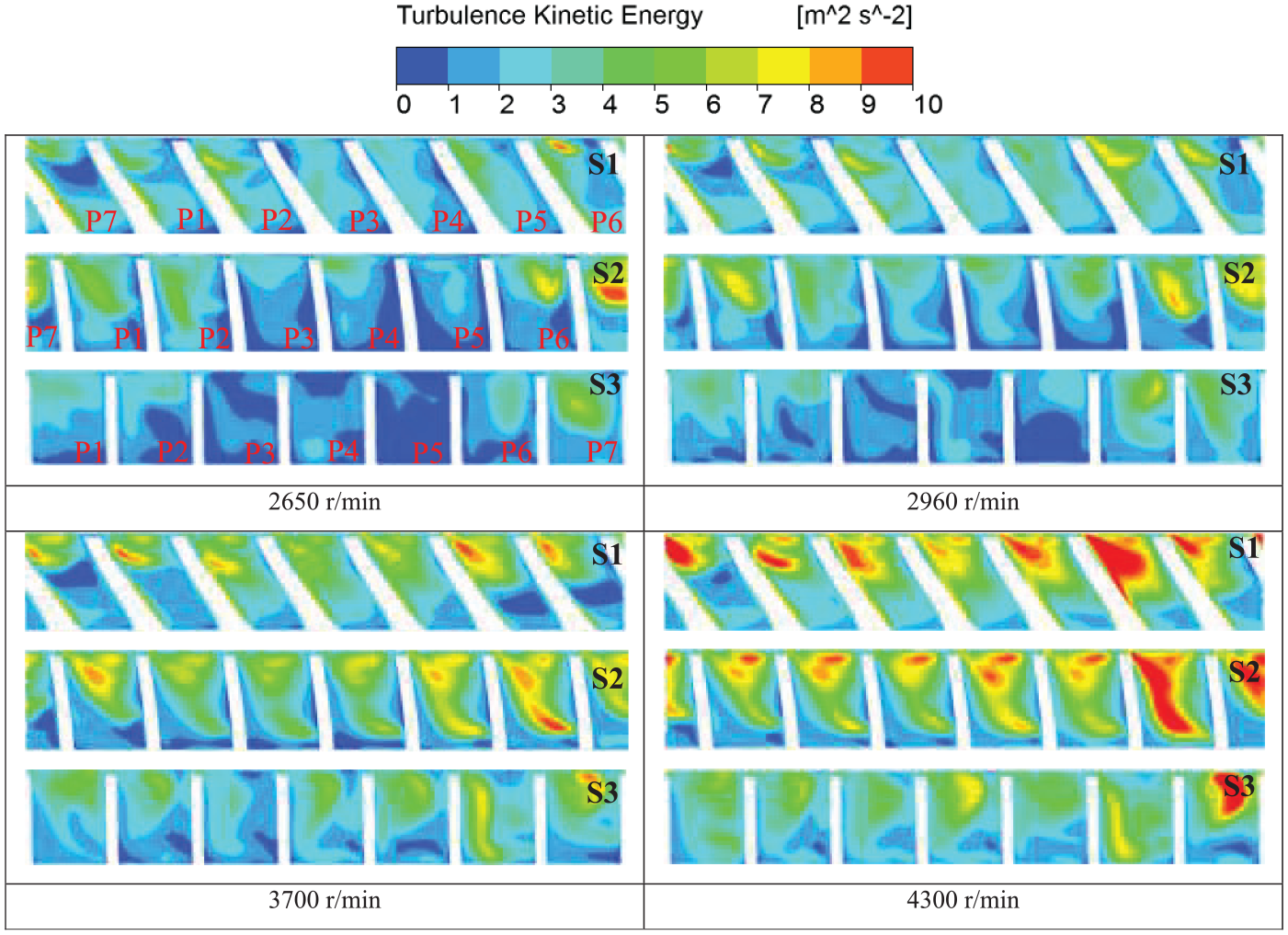
Distribution of turbulence kinetic energy at different flow sections with various rotating speeds.
Influence of temperature
Actually, the original design method for ECWP is under the high temperature because the temperature of cooling water would increase as a result of the limit total volume. Thus, the temperature of the fluid should be considered in operation. Table 4 shows the head and efficiency under the condition of room temperature 25°C and 80°C at different rotating speeds. It could be known that the hydraulic efficiency of ECWP is well because the head and efficiency do not change much at different temperatures under the same speed. Moreover, the pump efficiency increases a little bit. The trend of external characteristic of ECWP under various rotating speeds does not change very much at the high temperature as well. That means the hydraulic performance of this ECWP is stable within a certain temperature range and the hydraulic design is qualified.
External parameters of ECWP under different temperatures.

ECWP: engine cooling water pump.
In order to evaluate the flow energy losses in impeller under different temperatures, the turbulence kinetic energy on the monitoring line (ML) in impeller flow channels is compared, which could be seen in Figure 14. R* represents the normalized radius of MLs. Figure 13 shows the position of ML. As the flow field in the flow channel of P1, P4, and P7 is serious according to the above analysis, the MLs are set in these channels. All the MLs are in the middle section of impeller and in the middle of flow channels. It could be seen from Figure 14, at low rotating speed, the turbulence kinetic energy value is low at any flow channels. However, the value of turbulence kinetic energy increases a lot with the increase in rotating speed, and the area of high value of turbulence kinetic energy is near the outlet of impeller, which indicates the high energy losses in the impeller outlet. The turbulence kinetic energy value does not change much at the flow channel of P4 because it is far away from the tongue of volute. Furthermore, at various rotating speeds, the turbulence kinetic energy value does not change a lot at the front part of flow channels which means the temperature has little effects on the low-velocity flow fields, whereas the turbulence kinetic energy value changes a lot in the flow channel of P1 and P7 where it is near the tongue of volute. That means the change of fluid temperature would affect high-velocity flow fields at a certain degree, especially the rotor–stator interaction region. And, the effect of rotor–stator interaction effect of ECWP is sensitive to the temperature.
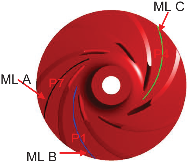
Diagram of monitor line.

Distribution of turbulence kinetic energy on monitoring lines under different rotating speeds and temperature: (a) ML A, (b) ML B, and (c) ML C.
Cavitation performance
From the above-mentioned results, it is known that the effect of rotating speed on the internal flow fields without cavitation. But, the cavitation performance of ECWP is also an important factor. Thus, the cavitation performances of ECWP under various speeds are compared. As the head pump at 3700 r/min is too low and the head drop at that condition is meaningless, the cavitation performance of pump under the speed of 2960, 3700, and 4300 r/min, operating at the flow rate of 340 L/min, is investigated. Figure 15 shows the cavitation performance of ECWP under various rotating speeds. Based on the requirements of national standard, the critical point of cavitation is marked by the NPSH at which the head has fallen by 3%. In the pump fields, it is known that the internal flow velocity increases with the increase in flow rate under the same speed and then results in the augment of critical cavitation performance, decrease in pressure and specific speed of cavitation, which induces the decrease in anti-cavitation performance.

Cavitation performance with different speeds.
It can be found from Figure 15 that the NPSHr is 6.21, 6.27, and 6.46 m that corresponds with the speed of 2960, 3700, and 4300 r/min, respectively. But, in order to compare the cavitation performance at the same criteria, the cavitation similar law should be employed. Based on cavitation similar law, the NPSHr under the speed of 2960 and 4300 r/min is transformed to the head under the speed of 3700 r/min. Table 5 demonstrates the comparison between transformed NPSHr and the original NPSHr. According to the comparison between them, the NPSHr increases with the growth of speed which means the anti-cavitation performance becomes worse. Hence, rotational speed of ECWP will not increase infinitely due to the effect of cavitation performance.
Comparison of NPSHr.

NPSHr: required net positive suction head.
As mentioned above, the value of NPSHr under various speeds is between 6 and 7 m. Thus, in order to compare the cavitation performance under various speeds, the vapor volume fraction under two conditions where it is near the NPSHr is selected to compare each other. Figures 16 and 17 show the iso-surface of vapor with 30% volume fraction under different inlet pressures (38.7 and 58.7 kPa). As concluded before, the cavitation performance of ECWP reduces with the increase in rotating speed. From Figure 16, it can be seen that the cavitation is serious under the low-pressure condition at pump inlet and the region with cavitation bubble drops at higher rotating speed conditions. When the rotating speed is 2960 r/min, the vapor bubble concentrates near the blade leading edge. The bubble in the impeller distributes non-uniformly within different flow channels. In the flow channels that just pass the volute tongue, the cavity is obviously larger. When the rotation speed increases to 3700 r/min, the cavity in all the flow channels increases. But, the bubble distribution in impeller flow channels is generally uniform except for some flow channels. Furthermore, the vapor bubbles block the flow channels and cause more energy losses which leads to the head drop of pump. When the rotating speed is 4300 r/min, the cavitation is more serious, and the vapor region further increases, while the distribution of bubbles is similar to the phenomenon of 3700 r/min. But, the vapor bubbles in some flow channels take more spaces. And, it can be found that the vapor starts to detach from the suction side of blade and forms a vortices cavity (C) which flows downstream with the main flow. From Figure 17, as the cavitation is not serious and the vapor bubbles generate initially, the cavitation is not serious as in Figure 16. However, when the rotating speed is 2960 r/min, the vapor bubble near the volute tongue is larger than other flow channels, which indicates the low pressure in that flow channels. And, the rotor–stator interaction may increase under cavitation condition under low rotating speeds.
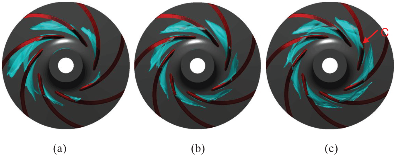
Iso-surface of vapor where the vapor volume fraction is 30% (ps= 38.7 kPa): (a) 2960 r/min, (b) 3700 r/min, and (c) 4300 r/min.
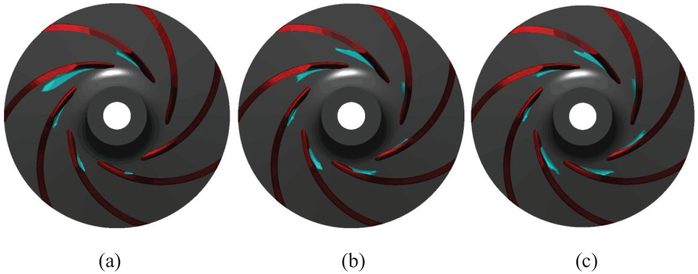
Iso-surface of vapor where the vapor volume fraction is 30% (ps= 58.7 kPa): (a) 2960 r/min, (b) 3700 r/min, and (c) 4300 r/min.
Conclusion
In this study, the performance of ECWP with variable rotating speeds is investigated based on simulation and experiment. The external characteristics and internal flow fields are studied. Some findings are as follows:
With the increase in rotational speed, the pump head increases but the high-efficiency region offsets to large flow rate conditions at the same time. Furthermore, the velocity magnitude at outlet of volute changes most and high-energy loss regions come up at the impeller outlet and in volute. The similar law is also verified by the less than 5% deviation between transformed head and original head.
The vortexes easily occur in the internal flow fields of ECWP under lower or higher rotating speed, and the turbulence kinetic energy increases a lot which makes the efficiency of ECWP to reduce. The turbulence kinetic energy value near the shroud is higher than that near the hub under the effects of tip leakage flow and the turbulence kinetic energy value changes much in the flow channel near the volute tongue. The rotor–stator interaction effect is sensitive to the temperature under various rotating speeds.
Under cavitation condition, the NPSHr increases with the increase in rotational speed that weakens anti-cavitation performance. The vapor bubble concentrates near the blade leading edge and distributes non-uniformly within different flow channels. And, the rotor–stator interaction may increase at lower rotating speed during cavitation conditions. The augment of rotating speed would deteriorate the internal flow fields and causes more energy losses. Therefore, the pump should be operated within a certain range of rotating speed in order to keep the high efficiency during operation.
Footnotes
Authors’ Note
Wei Li is currently affiliated with Institute of Fluid Engineering Equipment Technology, JITRI, Zhenjiang, Jiangsu, China.
Yongfei Yang is currently affiliated with College of Mechanical Engineering, Nantong University, Nantong, China.
Declaration of conflicting interests
The author(s) declared no potential conflicts of interest with respect to the research, authorship, and/or publication of this article.
Funding
The author(s) disclosed receipt of the following financial support for the research, authorship, and/or publication of this article: The work was sponsored by the National Natural Science Foundation of China (nos 51679111, 51409127), Synergistic Innovation Center of Jiangsu Modern Agricultural Equipment and Technology(4091600014), National Key R&D Program Project (no. 2017YFC0403703), PAPD, Key R&D Program Project in Jiangsu Province (BE2017126), Nature Science Foundation for Excellent Young Scholars of Jiangsu Province (no. BK20190101), Key R&D Program Project of Zhenjiang (no. SH2017049) Scientific Research Start Foundation Project of Jiangsu University (no. 13JDG105), and Postgraduate Research & Practice Innovation Program of Jiangsu Province (KYCX19_1601).