
Abstract
The quantitative relationship between the energy dissipation capacity of RC members and displacement deformation, cumulative energy dissipation and structural design parameters were established by the research group in the early stage, and then the damage index based on energy dissipation capacity and performance index limits were proposed. Based on the existing research, the seismic design method of RC square/rectangular column members for SDOF systems based on damage performance is proposed, and the method is introduced by an example. It is found that the seismic design method establishes a quantitative relationship between the structural design parameters and seismic parameters, which is convenient to guide the structural design. The increase in the ratio of transverse reinforcement can reduce the damage to RC column members, but when the ratio of transverse reinforcement exceeds a certain threshold value, the damage reduction effect is not obvious. The increase of the earthquake duration can aggravate the development of the damage to the RC column members, and the increasing effect is first fast and then slow. This seismic design method can make up for the deficiency that the duration effect is not considered in the current seismic code.
Keywords
Introduction
Displacement-based and bearing-capacity-based seismic design methods can reflect the amplitude and frequency characteristics of earthquakes, but fail to consider the impact of earthquake duration on structures.1–4 The energy-based seismic design method not only reflects the displacement deformation and bearing capacity, but also considers the cumulative energy dissipation damage caused by the earthquake duration,5–9 which can fully reflect the impact of earthquake action on the structure.
In 1985, the energy-based seismic design method at the theoretical level was first proposed by Akiyama, 10 but the design method was not directly used to guide structural design. In the same year, based on the test results of a large number of RC beam and column members, the Park-Ang damage index including deformation terms and energy dissipation terms was proposed.11,12 Then, the Park-Ang damage index was used as a damage evaluation criterion to study energy-based seismic design methods. Fajfar 13 found that in order to ensure that the Park-Ang damage index is less than 1, the ductility coefficient of the structure under earthquake should be less than the ultimate ductility under monotonic load. Therefore, it is proposed to compensate for the adverse effects of cumulative energy dissipation damage by limiting the ductility of the structure under earthquake. Chai et al. 14 considered this idea further and proposed an energy-based nonlinear design spectrum by setting the Park-Ang damage index to 1. Ye et al. 15 used the Park-Ang damage index to evaluate the energy dissipation damage of RC members and proposed the implementation framework of the energy-based seismic design method. According to different values of the Park-Ang damage index, a nonlinear design spectrum based on ductility constraints is proposed by Saman. 16 It can be seen that the researchers introduced the energy index into the structural design process, which is of great significance for the practical development of an energy-based seismic design. However, the coupling effect between the deformation term and energy dissipation term in the Park-Ang damage index has not been analyzed.17,18 Therefore, the applicability of the Park-Ang damage index as the damage evaluation standard is still questionable.
The research group obtained the decay law of energy dissipation capacity of RC members under variable amplitude loading history in previous research. The quantitative relationship between the energy dissipation capacity of RC members and displacement history (deformation term), cumulative energy dissipation (energy dissipation term) and structural design parameters was established, 17 and the damage index and performance index limits of RC members based on energy dissipation capacity were proposed. 18 Based on existing research, the seismic design process of RC square/rectangular column members for SDOF systems based on damage index was proposed, and the seismic design process was introduced as an example.
Damage index based on the energy dissipation capability
Expression of damage index
The damage index Dk of RC square/rectangular column members under variable amplitude displacement history is defined as
17


To establish the quantitative relationship between damage index Dk and seismic parameters, the cumulative energy dissipation capacity of target members EC is calculated from
19


Substitute Equations (7) to (13) into Equation (6), the cumulative energy dissipation capacity of the target RC members can be obtained.

9 RC members with different reinforcement conditions were subjected to low cycle reciprocating loading tests, 18 and the damage development of each half-cycles was recorded in detail to study the performance index limits of the damage index Dk. It is found that the apparent damage development process of 9 RC members is similar, the damage process of the 9 RC members can be divided into the following stages: (1) The first crack appeared on the concrete surface. (2) The cable-stayed cracks appeared, then the concrete cover appeared to have spalling damage at the interface. (3) The cable-stayed cracks developed into cross cracks, and the concrete cover appeared to have severe spalling damage.(4) The core concrete was crushed, and the longitudinal reinforcement buckled. Figure 1 shows the damage development process of one of the 9 specimens. Table 1 presents the performance index limits of the damage index Dk. More details can be found in Wang et al. 18

The damage development process.
Performance index limits of the damage index Dk.

The yield moment of section My, the yield drift angle θy and the ductility factor μ are related to the cross-sectional dimensions and longitudinal reinforcement. The fundamental period T is related to the mass m and the stiffness of the structure. The seismic parameters are determined by the peak ground acceleration PGA, the peak ground velocity PGV and the duration of the strong motion td. Therefore, according to Equation (14), when the cross-sectional dimensions, longitudinal reinforcement, fundamental period and seismic parameters are determined, the damage index Dk (performance design target) establishes a corresponding relationship with the ratio of transverse reinforcement ρsv, that is, when the owner proposes the expected performance design target at the end of the earthquake, the designer can obtain the corresponding ratio of transverse reinforcement ρsv according to Equation (14). Figure 2 shows the seismic design process of RC square/rectangular column members based on damage index Dk.

The seismic design process of RC square/rectangular column members based on damage index Dk.
The seismic design process of RC square/rectangular column members based on damage index can be divided into the following four steps.
The elastic design stage under minor earthquakes is consistent with the Chinese code for seismic design of buildings (GB50011-2010). 23 Firstly, the cross-sectional dimensions of the target member are preliminarily estimated, and the mass m and the representative values of gravity load are calculated. According to the most unfavorable combination of seismic load effect and gravity load effect, the longitudinal reinforcement of target members can be obtained. Secondly, based on the cross-sectional dimensions and longitudinal reinforcement, the yield moment of section My and the yield drift angle θy can be calculated.
Calculation of μ
The finite element analysis software MIDAS Gen (2021 v2.1) is used to carry out pushover analysis on the designed SDOF systems, and the capacity curve of the structure can be obtained. The acceleration response spectrum of the code for seismic design of buildings is transformed into the demand spectrum curve, then the target performance point of the structure can be obtained by comparing the capacity curve with the demand spectrum curve. The ductility factor μ1 of the structure can be obtained by dividing the spectrum displacement value at the target performance point under moderate earthquakes by the spectrum displacement value at the yield displacement on the capacity curve. Similarly, the ductility factor μ2 of the structure can be obtained.
Calculation of ρsv
According to the expected performance target value (Dk) selected by the owner under moderate earthquake, the cross-sectional dimensions and longitudinal reinforcement (My, θy), the fundamental period T (m), the ductility factor μ1 and the seismic parameters (PGA, PGV, td), the ratio of transverse reinforcement ρsv1 under moderate earthquakes is calculated by Equation (14). Similarly, the ratio of transverse reinforcement ρsv2 under major earthquakes can be obtained.
Determination of ρsv
Comparing the ratio of transverse reinforcement ρsv1 calculated under the moderate earthquake and the ratio of transverse reinforcement ρsv2 calculated under the major earthquake, the larger value of the two is selected as the target ratio of transverse reinforcement. If the increase of ρsv still cannot achieve the expected performance target, it is necessary to limit the ductility by increasing the cross-sectional dimensions or adding the longitudinal reinforcement of the RC column member to achieve the expected performance target.
Examples
Application of the seismic design of RC square/rectangular column members based on damage index
This section takes a SDOF structural as an example to introduce the application of the seismic design method based on damage index. Figure 3 shows the SDOF structural model. Table 2 shows the design details of the SDOF structural. Referring to Table 2, b × h refers to the cross-sectional dimensions. H and l represent the height of columns and the span of beams, respectively. c refers to the thickness of the concrete cover. In the example, the seismic intensity is 8 degrees (0.2g), the design earthquake group is Group 1, the site category is Category II, and the floor load is 100kN/m. 2

The SDOF structural model.
Design details of the SDOF structural.

The finite element analysis software Midas Gen is used for calculating the design parameters under minor earthquakes. The yield drift angle θy of the column members can be obtained from Equation (15),
24
and the yield moment of the column end section My can be obtained from Equation (16).
23


Since the reinforcement of the four RC column members is the same, column ① is selected as an example for the introduction. The calculation results of the reinforcement and related design parameters are shown in Table 3.
The calculation results of the reinforcement and related design parameters.

The finite element analysis software MIDAS Gen is used for pushover analysis of the designed SDOF systems to obtain the target performance points of the structure. Figure 4 shows the pushover analysis curves, the abscissa is the displacement spectrum Sd, and the ordinate is the acceleration spectrum Sa. According to the spectrum displacement value Sdm at the target performance point and the spectrum displacement value Sdy at the yield displacement on the capacity curve, the ductility factors of the structure can be obtained from Equation (17). Table 4 shows the ductility factors under moderate earthquakes and major earthquakes.

Pushover analysis curve.
The ductility factors under moderate earthquakes and major earthquakes.

When the seismic intensity is 8 degrees (0.2g), it can be seen from the code for seismic design of buildings that the PGA for time history analysis under moderate earthquakes and major earthquakes are 196cm/s2 and 400cm/ s2, respectively. When the site category is Category II and the design earthquake group is Group 1, the ratio of the PGV to the PGA is 0.15s. 25 Therefore, it can be obtained that the PGV under moderate earthquakes and major earthquakes are 29.4 cm/s and 60 cm/s, respectively.
Determination of earthquake duration
According to the reference, 25 when the earthquake duration td is in the range of 0∼10s, the damage to the RC members develops rapidly. When the earthquake duration td is in the range of 10∼20s, the damage development of the RC members slows down. When the earthquake duration td is in the range of 20∼30s, the increase of earthquake duration has relatively little effect on the damage development of RC members. Therefore, the earthquake duration 2.5s, 5s, 10s, 15s, 20s and 30s are selected in the example.
Seismic design results of RC square/rectangular column members based on damage index
The cumulative energy dissipation capacity can be obtained by Equation (7) to (13). Substitute the cumulative energy dissipation capacity of target members EC and structural design parameters (My, θy) into Equation (6), the target ratio of transverse reinforcement for RC square/rectangular column members under different performance levels can be calculated. Calculation results for the ratio of transverse reinforcement as shown in Figure 5.

Calculation results for the ratio of transverse reinforcement.
It can be seen from Figure 5: (1) When the performance target (damage index Dk) is the same, the ratio of transverse reinforcement increases with the increase of the earthquake duration, that is, the increase of the earthquake duration can aggravate the development of damage, the higher the performance target, the more obvious this phenomenon. (2) When the seismic duration is the same, the damage index decreases with the increase of the ratio of transverse reinforcement, which indicates that the increase of the ratio of transverse reinforcement can effectively reduce the damage to RC column. members. (3) This seismic design method can make up for the lack of considering the earthquake duration in the current seismic code. For example, when the damage index Dk = 0.5, under the condition of earthquake duration (2.5∼20s), the ratio of transverse reinforcement can meet the demand according to the seismic code, but when the earthquake duration is greater than 20s, the ratio of transverse reinforcement can not meet the expected performance target according to the seismic code.
According to the performance design method in the code for seismic design of buildings, when the ductility factor μ<1, the structural members are intact after the earthquake action, when the ductility factor μ<1.5, the mild damage of structural members is allowed to appear after the earthquake action, when the ductility factor μ≈2, the moderate damage of structural members is allowed to appear after the earthquake action, when the ductility factor μ≈5, the structural members are nearly seriously damaged after the earthquake action. Table 5 shows the corresponding relationship between the performance index limits of the damage index and the ductility coefficient limits in seismic code.
Corresponding relationship between the performance index limit of damage index and the ductility coefficient limit in seismic code.
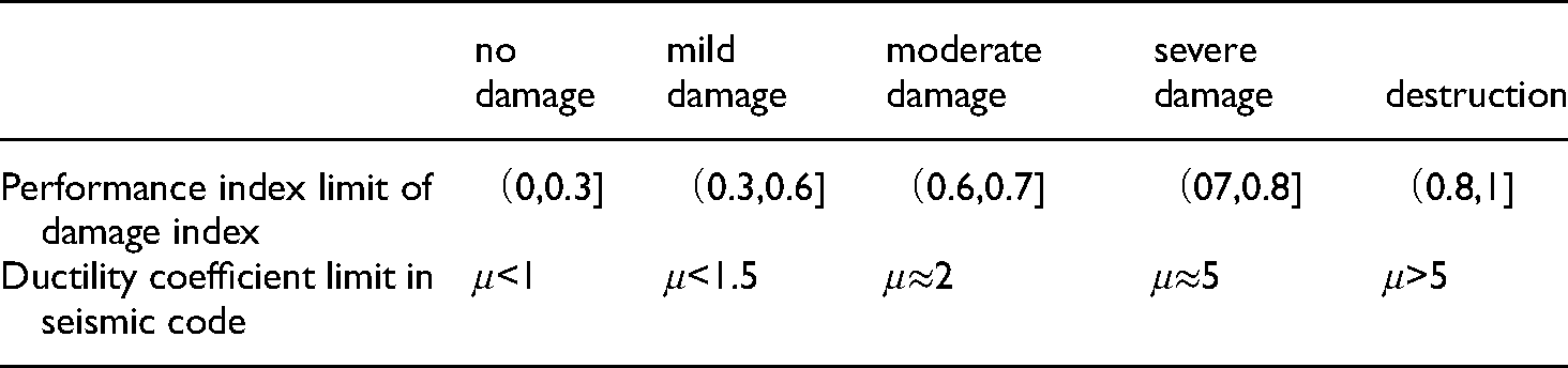
Corresponding relationship between the performance index limit of damage index and the ductility coefficient limit in seismic code.
To study the difference between the seismic design method based on damage index and the performance design method in seismic code, Dk∼ρsv∼td relations of different ductility factors are established based on the example. The Dk∼ρsv∼td relations under different ductility factors are shown in Figure 5. The x-axis represents the ratio of transverse reinforcement ρsv, which varies from 0.1% to 2%. The y-axis represents the earthquake duration td, which varies from 0 to 30s. The z-axis represents the damage index Dk, which varies from 0 to 1. Where, μ = 1.5, μ = 2 and μ = 5 means that the structural members designed according to the seismic code after the earthquake action can ensure mild damage, moderate damage, and severe damage respectively.
It can be seen from Figure 6: (1) The increase of the ratio of transverse reinforcement can reduce the damage to RC column members, but when the ratio of transverse reinforcement exceeds a certain threshold value, the damage reduction effect is not obvious, The increase of the earthquake duration can aggravate the development of the damage of the RC column members, and the increasing effect is first fast and then slow. (2) It can be seen from Figure 6 (a), (b) and (c), that with the increase of earthquake duration td, the damage index Dk exceeds the performance index limits of mild damage (Dk = 0.6), moderate damage (Dk = 0.7) and severe damage (Dk = 0.8), respectively. That is, with the increase of earthquake duration td, the performance design method of controlling ductility coefficient in the seismic code can not meet the expected damage, while the design method based on damage index can make up for the deficiency that the duration effect is not considered in the current seismic code.

Dk∼ρsv∼td relations under different ductility factors.
The following conclusions were drawn from the results of this study.
The seismic design process of RC column members based on damage index is proposed. This seismic design method establishes a quantitative relationship between the structural design parameters and seismic parameters, which is convenient to guide the structural design. The increase of the ratio of transverse reinforcement can reduce the damage to RC column members, but when the ratio of transverse reinforcement exceeds a certain threshold value, the damage reduction effect is not obvious. The increase of the earthquake duration can aggravate the development of the damage to the RC column members, and the increasing effect is first fast and then slow. This seismic design method can make up for the deficiency that the duration effect is not considered in the current seismic code.
This design process is limited to RC square/rectangular column members for SDOF systems with earthquake durations from 0 to 30s.
Footnotes
Acknowledgements
This research was supported by the National Natural Science Foundation of China (Grant No. 50908022), the Natural Science Foundation of Hunan Province (Grant No. 2022JJ40023, 2021JJ50157), the Scientific Research Project of Education Department of Hunan Province (Grant No. 20C0363, 18C0837).
Declaration of conflicting interests
The author(s) declared no potential conflicts of interest with respect to the research, authorship, and/or publication of this article.
Funding
The author(s) disclosed receipt of the following financial support for the research, authorship, and/or publication of this article: This work was supported by the National Natural Science Foundation of China, Scientific Research Project of Education Department of Hunan Province, Natural Science Foundation of Hunan Province, (grant number 50908022, 20C0363, 18C0837, 2022JJ40023, 2021JJ50157)
Author biographies
Yukui Wang received the Ph.D. degree from College of Civil Engineering, Changsha University of Science & Technology, Changsha, China in 2020. He is currently working at College of Civil Engineering, Hunan City University, China. His research interests is seismic energy dissipation capacity of buildings.
Zhefeng Liu received the Ph.D. degree from College of Civil Engineering, Hunan University, Changsha, China in 2006. He is currently working at College of Civil Engineering, Changsha University of Technology Changsha, China. His research interests is seismic energy dissipation capacity of buildings.
Dan Zhang received the Ph.D. degree from College of Civil Engineering, Kunming University of Science and Technology, Kunming, China in 2018. She is currently working at College of Civil Engineering, Hunan City University, China. Her research interests is seismic energy dissipation capacity of buildings.
Zhangqi Hu received the Ph.D. degree from College of Civil Engineering, Hunan University, Changsha, China in 2018. He is currently working at College of Civil Engineering, Hunan City University, China. His research interests is seismic energy dissipation capacity of buildings.
Dong Yu received the Ph.D. degree from College of Civil Engineering, Hunan University, Changsha, China in 2017. He is currently working at College of Civil Engineering, Hunan City University, China. His research interests is seismic energy dissipation capacity of buildings.