
Abstract
Seven prestressed concrete beams and one normal concrete beam were tested to study the seismic performance of concrete beams with prestressing carbon fiber reinforced polymer tendons. The failure modes, hysteretic curves, ductility, stiffness degeneration, and energy dissipation capacity were studied systematically. This study shows that the partial prestressing ratio is the main factor that affects the seismic performance of carbon fiber reinforced polymer prestressed concrete beams. The beam is more resilient to seismic loads as the partial prestressing ratio decreases. Under the same partial prestressing ratio value, the energy dissipation capacity of prestressed concrete beams with unbonded carbon fiber reinforced polymer tendons was better than that of prestressed beams with bonded carbon fiber reinforced polymer tendons. When combining both bonded and unbonded prestressing carbon fiber reinforced polymer tendons, the ductility index of concrete beams was improved. Compared with that of fully unbonded and fully bonded carbon fiber reinforced polymer prestressed concrete beams, the ductility index of concrete beams with combined bonded and unbonded prestressing tendons increased by 26% and 12%, respectively.
Keywords
Introduction
Fiber reinforced polymer (FRP) tendons can be used as prestressing tendons or reinforcements in concrete components. The potential of FRP tendon lies in its light weight, high strength, and excellent resistance to corrosion, which speeds up the process of construction and reduces maintenance costs. In addition, various cross-sectional shapes and material combinations can be applied in FRP manufacturing and are otherwise difficult to achieve when producing conventional steel materials. Nevertheless, FRP tendons also have different material compositions and lower transverse strengths than steel cables. During the late 1980s and throughout the 1990s, the application of the FRP system has been used in some demonstration projects. The Marienfelde Bridge in Berlin, completed in 1988, is the first structure to be built with externally unbonded prestressing FRP tendons. Now, FRP tendons have been widely used in many projects across the world, such as the Badische Anilin-und-Soda-Fabrik (BASF) Bridge (1991, Germany), the Taylor Bridge (1997, Canada), and the Bridge Street Bridge (2001, Michigan).
To date, the seismic performances of prestressed concrete structures and normal concrete structures have been studied extensively. The moment-curvature characteristics and hysteretic model of fully bonded prestressed concrete beams were studied by Blakeley and Park. 1 Thompson and Park 2 presented the cyclic moment-curvature model for fully and partially prestressed concrete members and investigated their earthquake responses. Xue et al. 3 conducted an experiment to study the seismic performances of prestressed high-performance concrete (HPC) beams and proposed a hysteretic model for HPC beams. Zheng and Fang 4 carried out the experiment of seven prestressed composite beams under positive or negative moment action to test the seismic performances of prestressed steel concrete beams. In the quasi-static test, Yuan et al. 5 selected different load histories to study the hysteretic behaviors of concrete beams with normal prestressing steel cables. Yuan et al. 6 conducted a test on steel reinforced concrete beams with engineered cementitious composite (ECC) subjected to cyclic loadings. Regarding concrete beams using prestressing FRP tendons, static behaviors have been studied by many researchers.7–13 However, very few tests have been conducted to explore the seismic performance of concrete beams with prestressing FRP tendons. Yu 14 tested six concrete beams using fully bonded prestressing carbon fiber reinforced polymer (CFRP) tendons under low reversed cyclic loading. Influences of different jacking stresses, reinforcement ratios, and the partial prestressing ratio (PPR) were analyzed. Studies show that hysteretic curves of concrete beams with bonded prestressing CFRP tendons are far less well developed than those of beams with prestressing steel strands. Wang et al. 15 put macro-fibers into concrete beams with prestressing CFRP tendons to improve the ductility and seismic performance. Studies have shown that prestressing CFRP tendons could improve the ultimate flexural capacity of the prestressed beams, and macro-fiber concrete beams with prestressing CFRP tendons had better seismic performance and ductility than those of concrete beams with prestressing steel cables.
In reality, concrete beams are often subjected to dynamic loads. In particular, brittle failure occurs in concrete beams with prestressing FRP tendons due to the brittle linear materials of FRP, which decrease the energy dissipation and seismic behavior of beams. The seismic performance of concrete beams with prestressing FRP tendons is crucial to the safety of concrete structures. Despite the increasing popularity of using prestressing FRP tendons in concrete structures, the understanding of the seismic behavior of concrete structures using prestressing FRP tendons is still limited, and the effect of the bonding condition of prestressing FRP tendons on the seismic behavior of concrete beams has not been fully explored. To study the seismic behavior of concrete beams with prestressing FRP tendons, experimental investigation is needed.
This study explores the seismic performances of concrete beams using prestressing CFRP tendons. CFRP tendon is a typical and widely used prestressing material because CFRP has higher strength, less creep, and better fatigue behavior than glass fiber reinforced polymer (GFRP) and aramid fiber reinforced polymer (AFRP). Eight concrete beams were tested until failure, undertaking low reversed cyclic loading tests. The failure modes, hysteretic curves, ductility, stiffness degeneration, and energy dissipation capacity were studied in detail through experimental investigation.
Experimental program and procedure
Test beams
All concrete beams are identical in terms of dimensions (200 mm × 300 mm × 3200 mm). Eight beams were constructed in all, of which four were prestressed with CFRP tendons, three were prestressed with steel cables, and the eighth beam is a normal beam for reference. The experiment considered three factors in the study: the PPR, bonding condition, and types of prestressing tendons. The variations of these factors are shown in Table 1.
Details of concrete beams.
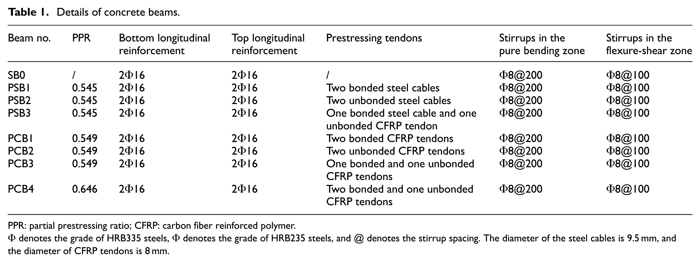
PPR: partial prestressing ratio; CFRP: carbon fiber reinforced polymer.
Φ denotes the grade of HRB335 steels, Φ denotes the grade of HRB235 steels, and @ denotes the stirrup spacing. The diameter of the steel cables is 9.5 mm, and the diameter of CFRP tendons is 8 mm.
The reinforcement details and configurations of the tested concrete beams are shown in Figures 1 and 2. All beams were reinforced with four ordinary steel bars longitudinally. Two of these steel bars, 16 mm in diameter, were located in the top of the concrete beams, while the other two 16-mm-diameter steel bars were placed at the bottom of the beams. Steels, 8 mm in diameter, were reinforced with shear reinforcements to ensure flexural performance of the beams up to shear failure. Like the steel cables, the distance between the bottom row of CFRP tendons and the bottom of the beam was 60 mm.
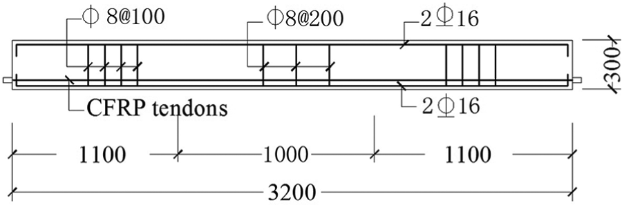
Construction drawing of specimen (mm).
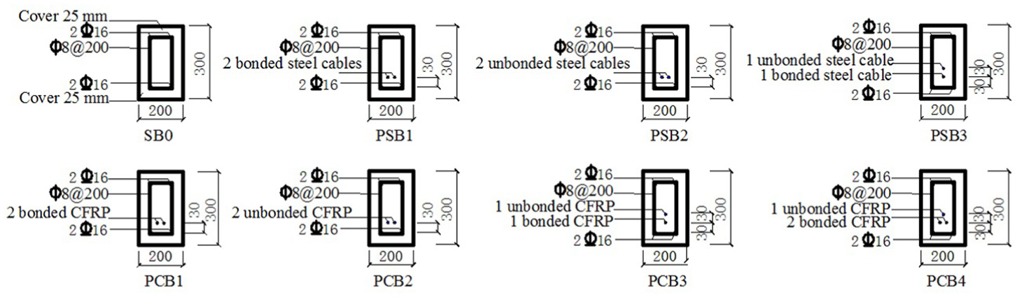
Configurations of the cross-section of each beam.
All beams were constructed from the same steel reinforcements and the same concrete, and the mechanical properties of the steels and the concrete of each beam were identical. The compressive strength of the cube concrete was measured at 28 days, and three tested concrete specimens were 150 × 150 × 150 mm. The measured cubic compressive strength and modulus of elasticity of the concrete are presented in Table 2. The mechanical properties of steels and prestressing tendons are presented in Table 3.
Mechanical properties of concrete.

Mechanical properties of steels and prestressing tendons by test.

CFRP: carbon fiber reinforced polymer.
The concrete beams were prestressed with 9.5-mm steel cables or 8-mm CFRP tendons approximately 30 days after casting. The bonded prestressed concrete beams were then grouted to ensure the firm bond between the concrete and CFRP tendons or steel cables. The grouting materials were mixtures of high-strength, non-shrink grouting aggregates with early strength cement (42.5 R). The tested cubic mortar specimens were 70.7 × 70.7 × 70.7 mm. The average compressive strength of the cubic mortar specimens is 50.75 MPa at 28 days after the grouting. All steel cables and CFRP tendons were pre-tensioned to 62% of their ultimate tensile strength. The anchor of CFRP tendons is a bond-type anchorage system.
Instrumentation
The strains of CFRP tendons and steels were measured using electrical strain gauges, and the layout of the measuring points is shown in Figure 3. The concrete strain gauges were attached on the lateral and top surface of the concrete beams. A linear voltage displacement transducer (LVDT) was set at the middle of the concrete beams to measure deflection of the beam during the tests.

Layout of the measuring points.
The formation and growth of cracks were marked at each load step. The strains of CFRP tendons or steel cables during the prestressing and testing process were all measured by strain gauges attached on them.
Testing procedure
The application of two point loads was used, a 25-ton hydraulic jack in increments at one-third of span distance from the supports, as shown in Figure 4. The loading rate was 0.2 mm/s.

Loading figure (mm).
Figure 5 shows the loading scheme of the tests proposed by JGF/T 101. 16 The concrete beams were loaded to crack in the pure bending sections in the first cycle, which is load controlled. The load is defined as Pcr corresponding to the cracking of the beams. In the subsequent cycles, the beams were displaced to Δp in one cycle, which are all displacement controlled. Here, Δp corresponds to the incremental displacement of the concrete beams in the middle of the span. The beams were displaced to 4 mm for every cycle, except Δp = 6 mm for the last cycle. To eliminate the hot oil temperature of the pump, all beams were loaded with only one cycle for each incremental displacement. Loading for a long time will cause the temperature of the hydraulic oil to rise, and the oil pump will give a warning or even stop working if the temperature of the hydraulic oil is too hot. If the hydraulic jack is stopped, the test will stop, and the experimental data will be intermittent. The displacements are multiples of Δp in successive sets of cycles, namely, +1Δp, −1Δp, +2Δp, −2Δp, +3Δp, −3Δp.

Scheme of loading.
Test results and analysis
Test observations and results
Typically, for all the tests, first cracks in the beams were observed between the loads, which were flexural cracks. During the +2Δp and −2Δp loading cycles, flexure-shear cracks were observed between the supports and load points. Subsequently, the existing cracks continued to propagate without the formation of new cracks, and they gradually penetrated across the full depth of the beams.
All concrete beams are flexural failure, and concrete beams with different prestressing tendons have different failure modes. Figure 6 depicts the typical failure phenomena of the concrete beams. It can be seen that the concrete was crushed between the two concentrated loads with the buckling of the top longitudinal steels. For the normal concrete beam and beams prestressed with steel cables, the failure patterns are the crushing of the concrete only. The concrete beams with prestressing CFRP tendons have two kinds of failure patterns: the crushing of the concrete only for the unbonded concrete beams and the rupturing of CFRP tendons for the bonded concrete beams and for concrete beams that combined both bonded and unbonded prestressing tendons. The rupturing of CFRP tendons is accompanied by crushing of the concrete. This is mainly due to the release of elastic energy, which is absorbed by the concrete after the rupturing of CFRP tendons. The tensile strain of the broken CFRP tendons, which is measured by attached strain gauges, reaches the ultimate tensile strain.
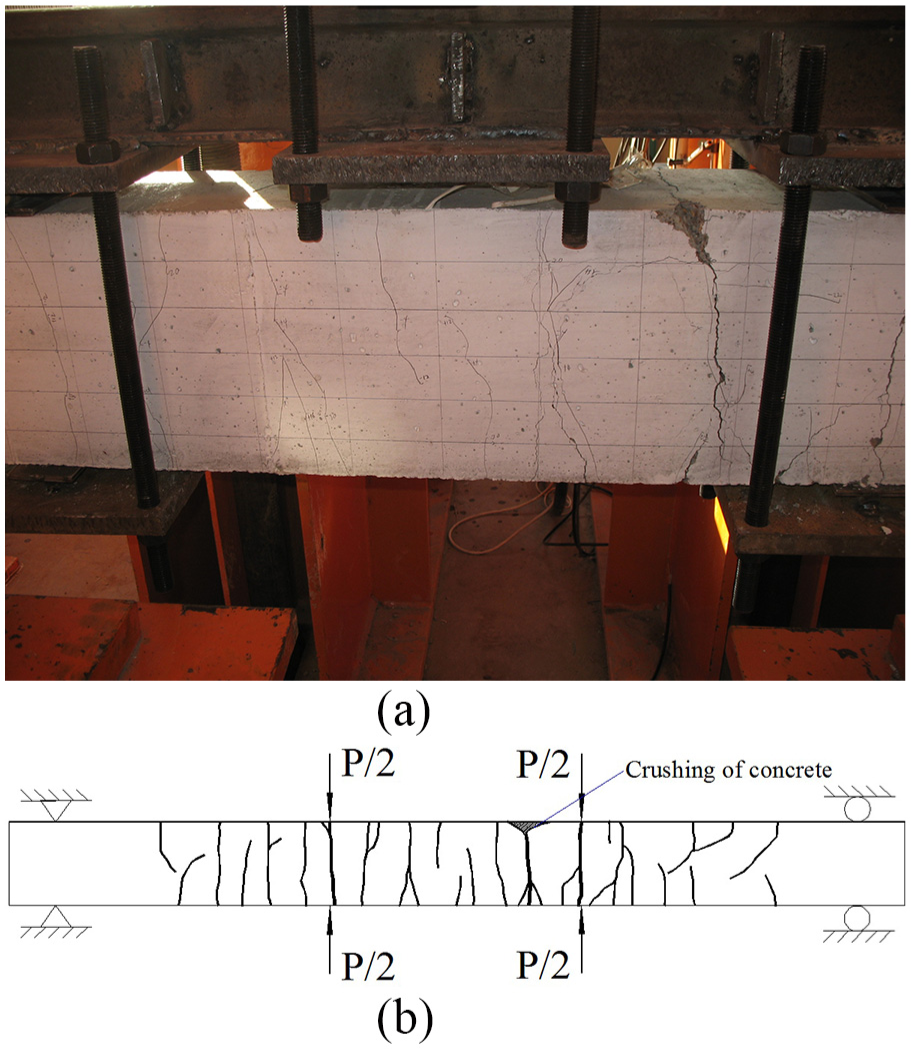
Damage of specimen: (a) failure model of beam PCB-2 and (b) distribution of cracks in beam PCB-2.
In this study, the measuring range LVDT is limited to 50 mm. The concrete beams were considered broken when the maximum width of cracks was beyond 5 mm. The main test results and failure patterns of the concrete beams are all listed in Table 4.
Main test results of concrete beams.

CFRP: carbon fiber reinforced polymer; Pcr: the cracking loads of beams; Py: the yielding loads of beams; Pu: the ultimate loads of beams; Δy: the yielding deflection of beams; Δu: the ultimate deflection of beams; λ: the ductility index; λavg: the average of the ductility index.
Hysteretic curves
The hysteretic curves can be used to analyze the seismic elastic–plastic responses of the structures. Hysteretic curves (P-Δ curves, P is the load applied to the beams in the vertical direction at the loading points, and Δ is the vertical deflection of the beams at mid-span.) of the tested beams are shown in Figure 7.

Hysteretic curves of beams: (a) SB0, (b) PCB1, (c) PCB2, (d) PCB3, (e) PCB4, (f) PSB1, (g) PSB2, and (h) PSB3.
The following can be seen from Figure 7: (1) the relationships of P and Δ are largely linear before the cracking of the beams. After cracking of the beams, the hysteretic curves demonstrate a plastic relationship and retain some residual deformation. (2) Compared with the full hysteretic loops of the concrete beam SB0, the pinching phenomenon of the hysteretic loops of prestressed concrete beams is apparent, particularly the fully bonded prestressed beams PCB1 and PSB1. Consequently, prestressed concrete beams would have smaller hysteretic areas than normal concrete beams. (3) PPR is a major factor that affects the seismic performance of prestressed beams. The pinching phenomenon of the hysteretic loops of beam PCB4 is more apparent than that of beam PCB2, which leads to the hysteretic area of PCB4 being smaller than that of PCB2. The seismic resistance gradually decreases with increasing PPR. If PPR is the same, the energy dissipation capacity of the unbonded prestressed beam (PSB2, PCB2) is higher than that of the bonded prestressed beam (PSB1, PCB1).
Skeleton curves
The skeleton curves of all concrete beams are shown in Figure 8. The following findings can be obtained from the skeleton curves: (1) the curves of all beams consist of three lines: the first line is the uncracking phase, the second is the yielding phase, and the last line is the ultimate phase. (2) The bearing carrying capacity of the normal concrete beam SB0 remains relatively consistent at the ultimate phase. However, the load-carrying capacity of the prestressed beams has a significant increase during upward loading at the ultimate phase. (3) Compared with the same reinforcement as used for the fully unbonded beams PCB2 and PSB2, the ultimate flexural strength of fully bonded beams PCB1 and PSB1 was increased by 10.66% and 22.52%, respectively. With the same reinforcement, the ultimate flexural strength of the fully bonded prestressed beams is higher than that of the unbonded prestressed beams. When combined with bonded and unbonded prestressing CFRP tendons (PCB3 and PCB4), the ultimate flexural strength of the prestressed beams decreases compared with that of the fully bonded prestressed beam PCB1. (4) The ultimate capacities of concrete beams with prestressing CFRP tendons are lower than those of beams with prestressing steel cables. Comparing the fully bonded prestressed beams PCB1 and PSB1, the ultimate strength of PSB1 was increased 4.01% compared with PCB1. In addition, unlike CFRP tendons, the steel cables cannot be ruptured, and the ultimate deflection of the beams with prestressing steel cables is larger than that of beams with prestressing CFRP tendons. The ultimate deflection of PSB1 was increased 19.41% compared with PCB1. (5) The curves of the prestressed beams are quite close to those of the normal concrete beam in the negative loading direction, indicating that the prestressing force has little effect on the bearing capacity of concrete beams reinforced with the same compressed steels in the upward loading direction.

Skeleton curves of concrete beams.
Ductility
Conventional ductility indices always include the onset of yielding of steels. However, FRP has no yielding point, such that conventional definitions are not appropriate to evaluate the ductility of concrete beams with prestressing CFRP tendons. Feng et al.
17
proposed new deformability indices for concrete elements made of FRPs. The new index is given as
The ductility index λ of the normal concrete beam and the prestressed beams with steel cables refers to the stage where the maximum width of cracks at mid-span has not reached 5 mm. From the results, the following conclusions can be drawn: (1) when combined with bonded and unbonded prestressing CFRP tendons, the ductility index of the concrete beams increases by 12.05% and 26.13% when compared with the ductility index of fully bonded and unbonded prestressed concrete beams, respectively. (2) The PCB3 and PCB4 beams were combined with bonded and unbonded prestressing CFRP tendons, and only the PPR was different. The PPR of PCB4 was larger than that of PCB3, and the ductility of PCB4 decreased with increasing PPR. (3) The ductility of the beams with prestressing steel cables is higher than that of beams with prestressing CFRP tendons. When the initial prestressing is the same, the ductility index λ of the beams with prestressing steel cables is higher by 20%–50%.
Stiffness degradation
The stiffness of the test beams, which is defined as K = P/Δ, and the stiffness degradation of beams during the entire loading process are shown in Figure 9. Based on the stiffness degradation curves, the following can be seen: (1) from the cracking stage to the yielding stage, the stiffness of the normal concrete beam and prestressed concrete beams degrades significantly. (2) The rigidity degeneration curve of normal concrete beam SB0 sits at the bottom of the curves because the initial stiffness of prestressed concrete beams is larger than that of the normal concrete beam. The results also show that the ultimate stiffness of prestressed beams is apparently greater than that of normal concrete beams. (3) The increase of PPR would slow down the stiffness degradation of the prestressed concrete beams, shown by comparing the degeneration curves of PCB4 and PCB3. It could also be observed that the stiffness degradation is independent of the bonding conditions and types of prestressing tendons. The stiffness degradation curves of PCB1 and PSB1 are the same as those of PCB2 and PSB2.

Rigidity degeneration of concrete beams: (a) with prestressing CFRP tendons and (b) with prestressing steel cables.
Energy dissipation capacity
The area enclosed by the P-Δ curve in a single cycle is calculated to evaluate the energy dissipation of the concrete beams. The energy dissipation and the cumulative energy dissipation in the eight beams during testing are shown in Figures 10 and 11, respectively. Table 5 summarizes the total energy dissipation coefficient of the beams and improved coefficients of prestressed concrete beams.

Energy dissipation of concrete beams: (a) with prestressing CFRP tendons and (b) with prestressing steel cables.

Cumulative energy dissipation of concrete beams: (a) with prestressing CFRP tendons and (b) with prestressing steel cables.
Energy dissipation coefficients of beams.

The data in Table 5 suggest that the energy dissipation of fully unbonded prestressed concrete beams with CFRP tendons (PCB2) is higher than that of fully bonded prestressed beams (PCB1). The amount of energy dissipated in fully unbonded prestressed beams with CFRP tendons is approximately 6.44% higher than that of fully bonded prestressed beams with CFRP tendons. The results of the energy dissipation capacity of concrete beams with prestressing CFRP tendons are different from the test results for beams with prestressing steel cables from the published literature. The main reason for this difference is that the failure models of concrete beams with different prestressing tendons are different. According to the test results, the steel cables will not rupture, but the bonded CFRP tendons are all broken at the ultimate loading stage. When PPR is the same, the deformation capacity of concrete beams with unbonded prestressing CFRP tendons is larger than that of beams with bonded prestressing CFRP tendons, so the energy dissipation capacity of the unbonded prestressed beams is higher than that of the bonded prestressed beams.
Because the prestressing tendons were placed at different layers in the combination of bonded and unbonded prestressing tendons, the energy dissipation coefficients of the combined prestressed concrete beams do not improve significantly. Under fully unbonded prestressing conditions, the energy dissipation of beam PCB2 with prestressing CFRP tendons is lower than that of beam PSB2 with prestressing steel cables. Under other bonded prestressing conditions, the amount of energy dissipation of beam PCB1 with prestressing CFRP tendons is higher than that of beam PSB1 with prestressing steel cables. The results suggest that the prestressed beams with bonded CFRP tendons can achieve better energy dissipation capacity than that of the beams with bonded prestressing steel cables.
Conclusion
Eight concrete beams were tested up to failure to study the seismic performance of concrete beams with prestressing CFRP tendons. The experiment considered three factors: the types of prestressing tendons, the PPR, and the bonding condition of prestressing tendons. Based on the experimental results, the following conclusions are drawn:
The failure patterns of all beams in tests were dominated by flexural effects. The concrete beams with prestressing CFRP tendons have two types of failure patterns: the failure pattern of the unbonded prestressed beam was the crushing of the concrete and the failure pattern of the bonded prestressed beam and the concrete beam that combined both bonded and unbonded prestressing CFRP tendons is the rupturing of the bonded CFRP tendons.
Compared with the full hysteretic loops of the normal concrete beam, the prestressing technology results in an evident pinching phenomenon in hysteretic loops. The hysteretic areas of prestressed concrete beams are smaller when compared with those of the normal concrete beams.
PPR is the main factor that affects the seismic performance of prestressed concrete beams. The seismic resistance gradually decreases with increasing PPR. When PPR is the same, the energy dissipation capacity of concrete beams with unbonded prestressing CFRP tendons is higher than that of beams with bonded prestressing CFRP tendons. The amount of energy dissipated in the concrete beams with unbonded prestressing CFRP tendons is approximately 6.44% higher than that of the beams with bonded prestressing CFRP tendons.
The ductility index λ of the prestressed concrete beams decreases with increasing PPR. The bonding condition of the CFRP tendon or steel cable can affect the ductility of the beams. When combined with bonded and unbonded prestressing CFRP tendons, the ductility index of the prestressed beam improves, increasing by 12% and 26% from the ductility index of fully bonded and unbonded prestressed concrete beams, respectively.
Footnotes
Declaration of conflicting interests
The author(s) declared no potential conflicts of interest with respect to the research, authorship, and/or publication of this article.
Funding
The author(s) disclosed receipt of the following financial support for the research, authorship, and/or publication of this article: This research was jointly funded by the National Key Research and Development Program of China, grant number 2016YFC0701100; the National Natural Science Foundation of China, grant numbers 51878028; and the Fundamental Research Funds for Beijing Universities, grant number X18146.