
Abstract
The prefabricated semi-rigid concentrically braced steel frame has always been the main form of residential steel structures, much work so far has focused on the earthquake-resistance performance of such structures. However, little attention has been devoted to systematic model testing, further effort is still required to explore the structural performance with experimental studies. Two semi-rigid concentrically braced steel frames were designed and tested to failure under reversed low-cyclic loading. The hysteretic curves, bearing capacity, energy dissipation capacity, ductility and stiffness degradation performance were studied in detail. Then the performance was compared to analyze the advantages and disadvantages of the two frames. The tests showed that the plastic deformation and damage were primarily concentrated at the braces, and the columns and semi-rigid connections exhibited hardly any plastic deformation. The specimens went through the elastic stage, elastic-plastic stage and failure stage during the tests. The results indicated the specimen with chevron braces has better seismic performance. The structure presents the characteristic of ductile failure on the whole. The steel frame and braces of the specimens cooperatively perform together so that the structure has two seismic fortification lines. The structure with chevron braces possesses an excellent bearing capacity, a high lateral stiffness, a reliable lateral-resistance performance and a strong energy dissipation capacity. In contrast, because of the premature fracture of the cross joints, the structure with X-shaped braces has a lower material utilization efficiency, which leads to a dramatic decrease in the bearing capacity and stiffness, as well as low ductility and a poor energy dissipation capacity.
Keywords
Introduction
As a conventional form in multi-story and high-rise steel structures, concentrically braced steel frames play an important role in building industrialization.1,2 It is generally accepted that beam-column connections are assumed to be fully rigid or ideally hinged to simplify the calculation model. In practical engineering, however, the responses of the entire structure, members and beam-column connections to loads are all double nonlinear due to the material nonlinearity and geometric nonlinearity. Previous studies3–7 have demonstrated that the rotational stiffness of beam-column connections belongs to the semi-rigid category. In the Northridge Earthquake and Hyogoken-Nanbu Earthquake, massive brittle failure occurred for fully welded rigid connections. In contrast, the semi-rigid connections with high-strength bolts were almost completely intact,8,9 demonstrating that the semi-rigid connection has a better energy dissipation capacity and ductility. The reasonable election of the semi-rigid joints could optimize the distribution of the moment of the beams and make the beams achieve their full potential to bear load, which makes the design requirement of “strong column and weak beam” more likely to realize. The semi-rigid joints could offer the structure better deformability and dissipate more seismic energy to protect the structure. The extended end-plate bolted connection is a typical semi-rigid connection that has obvious economic advantages in manufacturing and installation. It has been widely used in the engineering of steel structures worldwide.10,11
By combining the concentric brace system and semi-rigid steel frame with extended end-plate bolted connections, the semi-rigid concentrically braced steel frame structure can be developed. The concentric braces can provide lateral stiffness to the frame; meanwhile, the semi-rigid connections can improve the structure’s deformability and energy dissipation capacity, which allows the structure to theoretically have great potential for excellent seismic performance. However, few studies have been devoted to model tests of semi-rigid concentrically braced steel frame structures. Li et al. 12 tested a full-scale model of a composite frame with semi-rigid connections on a shaking table. The results indicate that a composite frame with semi-rigid connections can be used in seismic areas. Guo et al. 13 tested six single-span two-story steel frames with connections with different details under cyclic loading. The results show that the frame with end-plate connections has a better bearing capacity and better hysteretic behavior than that of frames without end-plate connections. Zhang 14 tested twelve braces with variable cross-sections under quasi-static cyclic loading to study the hysteretic behavior and energy dissipation capacity. Then, semi-rigid steel frame models with variable cross-section braces were established by finite element analysis software to study their seismic behavior. The results show that semi-rigid steel frames with braces with variable cross-sections can reduce the lateral placement more effectively than that of rigid steel frames; however, the semi-rigid frames gained a greater seismic response because of the braces. Lu 15 conducted a pseudo-dynamic test on a semi-rigid concentrically braced steel frame. The result indicates that the semi-rigidity could effectively diminish the seismic response and that the concentric braces could improve the structure’s seismic performance acting as the first seismic fortification line. Therefore, systematic experimental studies on semi-rigid concentrically braced steel frames are still lacking.
Based on the extended end-plate bolted connection, chevron brace and X-shaped brace, two semi-rigid concentrically braced steel frames were tested until failure under low-cyclic reversed loading to study the hysteretic curves, lateral stiffness, energy dissipation capacity, ductility, and stiffness degradation performance in detail. Then, the seismic behavior of the specimens was compared, and advice was proposed for theoretical analyses and engineering applications.
Preparation of the test
Design of the specimens
Using SAP2000 software, pushover analysis considering the nonlinear influence and plastic hinge was conducted to design the tested frames. According to the Code for the seismic design of buildings (GB 50011–2010), 16 the story angle limitation was 1/250 under frequent earthquakes and 1/50 under rare earthquakes. The extended end-plate bolted connections were simulated by nonlinear elements with Takeda plastic properties. The load-displacement curves of the specimens are presented in Figure 1. The distribution of plastic hinges are shown in Figure 2. As shown in Figure 1, it was observed that the yield displacement of specimen SXBF and SCBF were 5.6 mm and 4.8 mm, respectively. Figure 2 showed that the occurrence orders of the plastic hinges were in accordance with the order of “brace-beam-column” and that the plastic hinges on the braces had almost achieved their full potential of energy dissipation, the plastic hinges on the beams and columns appeared as well and developed to lower degrees, which preliminarily met the demand of two seismic fortification lines. On the basis of these results, we concluded that the frames have been designed rationally and could be studied in pseudo-static tests. The basic parameters of the specimens are shown in Table 1.
Basic parameters of the specimens (unit: mm).


Load-displacement curves of the specimens.

Distribution of plastic hinges.
The tested frames are both single trusses with two spans and two stories. One of the spans has concentric braces, while another span is a semi-rigid steel frame without braces. The braces were welded with gusset plates. The dimensions of the specimens are shown in Figure 3. The details of the extended end-plate bolted connection are shown in Figure 4.

Specimen dimensions: (a) specimen with X-shaped braces and (b) specimen with chevron braces.
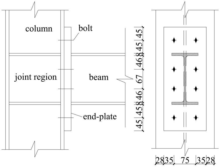
Structures of extended end-plate bolt connection.
Computation of the extended end-plate bolted connection
Using ABAQUS software, a finite element model of the connection was established to study its mechanical properties. The solid element C3D8R was selected for the simulation. The constitutive relation of the steel adopted the simplified classic three-straight-line model, its parameters were obtained by the tensile coupon test, the Poisson ration was set as 0.3. The manufacturer offered the constitutive relation of the high-strength bolts. According to the actual forced state, the boundary conditions of the finite element model were hinged column base, restricted translational displacement and rotational displacement on the top of the column. In order to prevent the beam’s lateral buckling and torsion, the beam end was constrained in the out-of-plane direction. The loads imposed on the model included axial force on the column, vertical load on the beam end and bolt pre-tightening force. The integrated finite element model is shown in Figure 5. The moment-rotation curve of the connection is shown in Figure 6. As shown in Figure 6, there is a obvious nonlinear relationship between the moment and rotation. In addition, to determine the stiffness of the extend end-plate bolted connection, the classification boundaries of joints in the Eurocode 3: Design of steel structures
17
was employed. The value of initial rotational stiffness

Finite element model.

Moment-rotation curve of extended end-plate bolt connection.
Tensile coupon test
The specimens are made from Q235B steel. The yield strength is
Test setup
The frame column bases were welded with ground beams to realize the boundary condition of the fixed end. Several lateral steel tubes were installed at the connections and the middle of the beams to ensure out-of-plane stability during the tests. There were pulleys between the tubes and specimens to diminish the adverse influence of friction. The vertical axial pressure was provided by three 30 t jacks, and the column axial compression ratio remained at 0.3. Cylic loading was imposed by a 100 t MTS actuator. The test setup of SXBF is presented in Figure 7.

Test setup: (a) Test setup designed and (b) Practical test setup.
Loading and measurement scheme
Based on the Specification for Seismic Test of Buildings (JGJ/T 101-2015),
19
the dual control loading-displacement method was applied in the tests. The loading increment control method was used before the specimens yielded. Two cycles were applied to each level at
The strain gauges and strain rosettes were arranged at critical positions, such as the column base, brace and beam end, to measure the internal force. The layout of the measuring points is shown in Figure 8. Moreover, some displacement meters were installed at the beam ends of both levels to measure the lateral displacement. In addition, to measure the integral displacement of the specimens, several displacement meters were installed on the ground beams. The measurement scheme of the displacement is illustrated SCBF as an example, which can be seen in Figure 7.

Measurement of the strain.
Test observations
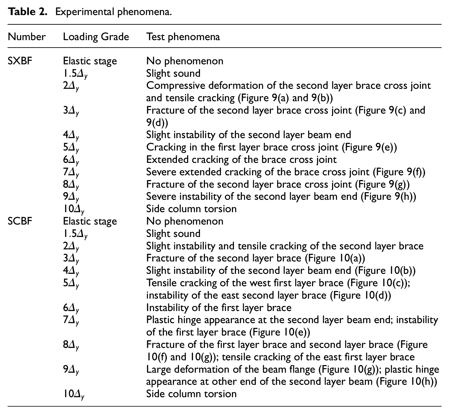
Table 2 presents the test phenomena of SXBF and SCBF during the tests. According to Table 2, the damage to the braces of SXBF was concentrated on the cross joints due to the state of multidirectional stress, and the brace plasticity did not develop adequately, which showed the characteristics of brittle failure. The damage of the SCBF brace manifested as out-of-plane instability in the middle and fracture near the gusset plates.
Experimental phenomena.

Failure phenomena of SXBF: (a) compressive deformation, (b) tensile cracking, (c) joint fracture, (d) severe joint fracture, (e) joint cracking, (f) severe joint cracking, (g) joint fracture, and (h) beam instability.

Failure phenomena of C-RB: (a) fracture of the brace, (b) slight instability of the beam, (c) tensile cracking of the brace, (d) instability of the brace, (e) instability of the brace,(f) plastic hinge, (g) instability of the brace, (h) fracture of the brace, (i) fracture of the brace, (j) tensile cracking of the brace, (k) plastic hinge, and (l) plastic hinge.
After unloading, the braces retained a large residual deformation and completely lost their bearing capacity. The beams of the span with braces retained little plastic deformation, while the beams of the other span had no residual deformation. Although the deformation of the column bases was not apparent, the strain data still showed that the column base had already entered the plastic stage. No obvious deformation was generated in the semi-rigid connections. The specimens mainly followed the failure order of “brace-beam-column.” The structure had two seismic fortification lines, which could satisfy the design requirements of “strong column and weak beam,”“strong joint and weak components” and China’s seismic code of “Three-Level performance objectivity,” namely, “undamaged under minor earthquake; repairable under moderate earthquake; no collapsing under major earthquake.”
Analysis of the test result
Hysteretic curve
The hysteretic curves of the specimens are presented in Figure 11. As shown in Figure 11, the curves show distinct yield processes and failure processes. According to the diagonal slope of the hysteretic loop, the hysteretic curves can be divided into three sections: (1) in the initial stage of loading,
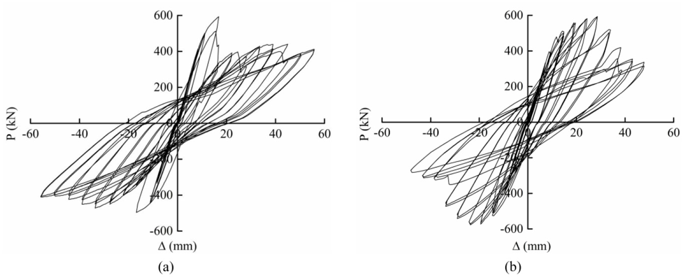
Hysteretic curves of the specimens: (a) SXBF and (b) SCBF.
Skeleton curve
The skeleton curves of the specimens are shown in Figure 12. The skeleton curves have good symmetry in the pushing and pulling directions. The initial elastic stiffness of the specimens are almost equal. The skeleton curves are both inverted S-shaped, which indicates that the loading process can be roughly divided into three stages: the elastic stage, elastic-plastic stage, and failure stage. In the elastic stage, the horizontal displacements of SXBF and SCBF are less than 11.2 mm and 9.6 mm, respectively, and the interfloor displacement angles are all lower than 1/268. In the plastic stage, the horizontal displacements of SXBF and SCBF are less than 39.2 mm and 28.8 mm, respectively, and the interfloor displacement angles are all lower than 1/76. The specimens entered the failure stage when
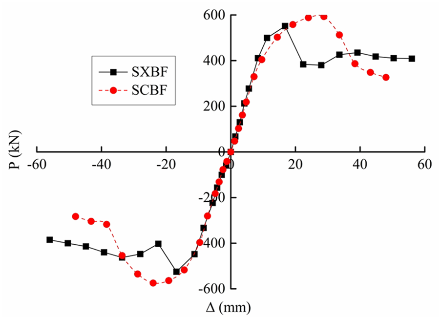
Skeleton curves of specimens.
The general yield bending moment method
20
was adopted to calculate the strength performance indexes of the specimens, as shown in Figure 13. Points A, B, C, and D correspond to the initial yield point, yield point, peak load point and failure load point of the specimens, respectively. The strength performance indexes of the specimens are listed in Table 3. According to the specification for the seismic test of buildings (JGJ/T 101-2015),
19
the failure load is assumed to be

General yield bending moment method.
Performance indexes.

On the basis of Table 3, the following findings can be obtained: (1) the yield load, peak load, and failure load are basically symmetric in the pushing and pulling directions with a slight difference, which is no more than 3.8%. (2) The maximum difference between the yield displacement, peak displacement, and ultimate displacement of the specimens in the pushing and pulling directions is approximately 15.0%. This is because out-of-plane instability occurs at the beam ends of the second story in the pushing direction after the braces fail. (3) The yield load of SXBF is 7.6% higher than that of SCBF. Nevertheless, the peak load and failure load are 8.7% lower than that of SCBF, given that the fracture on the cross joints impaired the bearing capacity of SXBF. (4) The ductility coefficient
Energy dissipation capacity
The structure’s energy dissipation capacity can be expressed by the energy dissipation coefficient

where
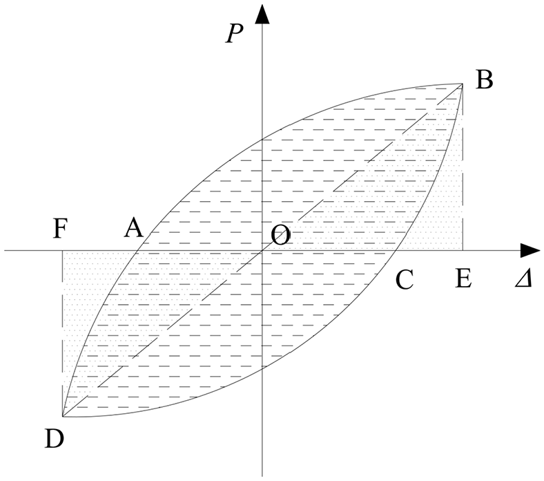
Load-displacement curve.
The curves of the cumulative dissipated energy and energy dissipation coefficients
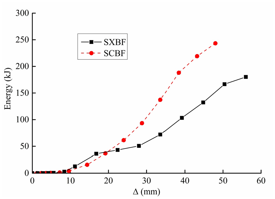
Comparison of the cumulative dissipated energy.

Comparison of energy dissipation coefficient.
Stiffness degradation
To reflect the stiffness degradation under low-cyclic reversed loading, the loop stiffness is taken for analysis and can be calculated by the following equation:
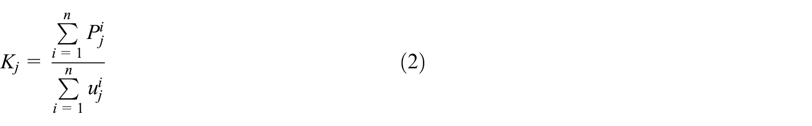
where
The stiffness degradation curves of the specimens are given in Figure 17. The following findings can be demonstrated and observed: (1) As the displacement increases, the stiffness of the specimens evidently degenerates. The degradation process can be divided into three sections on the basis of the degradation trend. When the specimens are in the elastic stage, the stiffness remains almost unchanged. When they enter into the elastic-plastic stage, the stiffness degenerates sharply because of the persistent damage to the braces. During the last several grades, the contribution of the braces is negligible, which leads to a mitigatory degradation trend. The semi-rigid frames also possess reliable lateral resistance performance. (2) At the beginning of loading, the stiffness of SXBF is 6.3% higher than that of SCBF; however, the specimens share almost the same stiffness in the end, showing that the stiffness degradation of SXBF is more severe than that of SCBF. (3) The sudden decrease in the stiffness of SXBF occurs both in the pulling and pushing directions, while the degradation curve of SCBF is smoother. Therefore, SCBF has a more secure lateral resistance performance.

Stiffness degradation curves of the specimens.
Bearing capacity degradation
The bearing capacity degradation performance reflects the degree of the decrease in the bearing capacity in each cycle at the same loading grade and can generally be evaluated by the capacity degeneration coefficient

When the displacement ductility coefficient is
The capacity degradation coefficients of the specimens are all listed in Tables 4 and 5, and some coefficients exceed one because of the measurement error. The data in the tables suggest that when the displacement ductility coefficient is lower than 4, the coefficient values for
Capacity degeneration coefficient (pushing direction).

Capacity degeneration coefficient (pulling direction).

Strain analysis
On the basis of the tensile coupon test, the yield strain

The measured positions.

Strain curves of key positions: (a) SXBF and (b) SCBF.
Conclusion
Two steel frames were tested to failure to study the seismic behavior of concentrically braced steel frames with extended end-plate bolted connections. Based on the analysis of the test phenomena and experimental data, the following conclusions are obtained:
The specimens both had distinct yield processes and failure processes under low-cyclic reversed loading and went through the elastic stage, elastic-plastic stage, and failure stage during the tests. The specimens presented the characteristic of ductile failure on the whole. In the elastic stage, the bearing capacity and lateral stiffness were provided by the braces and semi-rigid steel frame together. In the elastic-plastic stage, the braces yielded successively and dissipated energy acting as the first fortification line. In the failure stage, the damage and plasticity accumulated and made the braces disabled. The semi-rigid frames continued to bear the load and dissipate energy acting as the second fortification line, which could prevent the structure from collapsing under a major earthquake.
The plastic deformation and damage were basically concentrated on the braces. The failure of SXBF was mainly presented as the fracture of the brace cross joints, while the failure of SCBF was mainly presented as out-of-plane instability in the middle and fracture near the gusset plates of the braces. Although the plastic deformation of the columns and beams was not apparent, the measured strain data showed that plastic hinges had generated on the high stress parts. No deformation was generated on the semi-rigid connections. As a result, we can conclude that the specimens mainly followed the failure order of “brace-beam-column,” and the structure had two seismic fortification lines, which could satisfy the design requirements of “strong column and weak beam,”“strong joint and weak components” and China’s seismic code of “Three-Level performance objectivity.”
The steel frame and braces of the specimens perform cooperatively together. Specimen SCBF possesses an excellent bearing capacity, a high lateral stiffness, a reliable lateral-resistance performance and a strong energy dissipation capacity. By contrast, the braces of SXBF were not fully utilized because of the premature fracture on the cross joints, which led to the dramatic decrease in the bearing capacity and stiffness, and the ductility and energy dissipation capacity correspondingly worsened. The solution to the problem is that reasonable connections of the braces, such as bolted connections, should be adopted to prevent welding residual stress and premature failure, which will be the focus of our future work.
Compared to SXBF, SCBF has a better bearing capacity, stronger energy dissipation capacity, higher material utilization efficiency and more stable stiffness degradation performance. Hence, a semi-rigid steel frame with chevron concentric braces is recommended in practical engineering.
Future direction
Although the prefabricated semi-rigid concentrically braced steel frame has been preliminarily studied by pseudo-static tests, more research is still required to further explore the structure’s seismic performance. As the earthquake-resistance performance of concentrically braced steel frames can be significantly affected by semi-rigid connections, more kinds of semi-rigid connections should be taken into account, and relative test studies and finite element analyses will be conducted. In addition, since buckling restrained braces (BRBs) can yield without buckling and overcome the disadvantages of conventional braces, there is promising use for semi-rigid steel frames with BRBs, steel frames with BRBs and pinned connections in the future. Finally, the pseudo-dynamic test and shaking table test are preferred when available.
Footnotes
Declaration of conflicting interests
The author(s) declared no potential conflicts of interest with respect to the research, authorship, and/or publication of this article.
Funding
The author(s) disclosed receipt of the following financial support for the research, authorship, and/or publication of this article: This work is supported by Scientific Research and Development Project for Wall Material Innovation and Building Energy-saving of Shandong province of China (Lucaijianzhi[2014]139).