
Abstract
A highly integrated electromechanical actuator was developed in this article, which aims at fulfilling the requirements of high power-to-weight ratio, high efficiency, high integration and low volume in military equipment. Three different transmission schemes were proposed for the integrated electromechanical actuator according to the differences in integration methods. Comparative analysis was conducted on the specific structures of the integrated electromechanical actuator and the categories and performance of the planetary roller screw, which is the key unit of the integrated electromechanical actuator. An integrated electromechanical actuator was designed based on the project requirements. A mathematical model was established and the system transfer function was derived. Based on this, a simulation model of the position loop system was established using the AMESim software and the effects of some related parameters, such as friction, backlash and stiffness, on the dynamic performance of the system were investigated. The related theory and simulation results were experimentally validated by a self-developed integrated electromechanical actuator research prototype combined with the related test system. The data obtained from the step response tests, sinusoidal response tests and repeat locating accuracy tests indicated that the developed integrated electromechanical actuator prototype is of rapid, accurate and stable position tracking capability.
Keywords
Introduction
Actuation systems and devices are playing a dominant role in controlling the changes in attitude and direction during the aviation of aircraft or missiles. The pitching, yaw and rotating of aircraft are all completed by the cooperation of different control surfaces driven by the actuation systems. Owing to the development of the aerospace industries, demands on the volume and weight of the control surface parts, in particular for the power-to-weight ratio, intelligence, efficiency and automation of the actuation systems, are becoming more and more critical.1,2
In order to obtain higher aviation quality and actuating properties, power-by-wire (PBW) technique with better performance are increasingly used in aerospace industries to replace the traditional hydraulic system.3–5 Electrohydrostatic actuator (EHA) and electromechanical actuator (EMA) are known as the two typical categories of PBW devices.6,7 Compared with EHA, EMA devices employ decelerator and speed conversion devices, which are driven by the Servo-bidirectionally adjustable speed motor, to export force and displacement data, thus avoiding the hydraulic system. 8 Given a constant power level, EMAs have advantages of lower volume, higher efficiency, no potential for oil leaking and so on, in comparison to EHA. 9 In addition, the replacement of hydraulic power with electric power endows EMA with one of the critical technologies for evolution towards all-electric aircraft from multiple-electric aircraft. 10 It should be noted that there is a huge difference in the requirements on structural configurations and power levels of EMA when given different applications. The research in this article mainly focuses on the linear EMA with the output of linear displacement and force.
The emergence of EMA technology in aerospace engineering started around the mid-20th century, which was mainly adopted in driving the control surface of missiles. 11 After entering the 21st century, scientists are becoming interested in exploring the applications of EMA in space. For instance, the Vega carrier rocket launched by the European Union had two EMAs in each thrust vector control (TVC) system. 12 The EMA landing gears supplied by MOOG were applied by the US Air Force in F-35 aircraft. An all-electric primary flight control system with EMA was first implemented in helicopters in the ‘HEAT’ project in the United Kingdom. A project named ‘Smart Wing’ was initiated by a French company SAFRAN, which aims at investigating the electric controlled surface. 13 Regarding the civil airliner industry, the EMA was used in the right aileron of Airbus A320 and the performance was tested. Meanwhile, the EMA is also installed in the reverse propulsion system in both A350 and A380 airplanes and in the horizontal stabilizers of the latter.14,15 In addition, the EMA is used in the landing gear broke, mid-spoiler surface and horizontal stabilizer in the Boeing 787 aircraft. 16 Generally, the EMA saw a rapid development in the recent two decades, benefitting from the improvement of the motor and control technologies. A research carried out by the EPAD in the United States reports that, given all the flight control surfaces assembled by the integrated EMA, great reduction in the fuel consumption can be achieved. Regarding the fighters, the takeoff weight can be reduced by around 600–1000 lbs owing to no necessity for the oil circuit and 14% of the body area susceptible to small arm damage can be minimized. The energy dissipation is also lower for the EMA cases given the same output condition.17,18 Furthermore, the above-mentioned indexes will be further improved if the integrated electromechanical actuator (IEMA) with a lower volume and higher power-to-weight ratio is adopted.
The currently used liner EMA devices mainly present as serial or parallel structures, which can be further optimized in aspects of the volume and power-to-weight ratio. To provide an improvement in the system integration, an IEMA configuration was proposed in this article, which was featured with less components and elimination of the reducer. The former decreases the possibility for the mechanical stuck of the actuator and thus increases the robustness, while the latter increases the working efficiency, decreasing the overall weight and moment of inertia, which finally prevents the effects of the gear backlash on the system accuracy. A reduction was achieved both in weight and volume, thus increasing the integration. Therefore, it can be concluded that research on the fabrication and dynamic evolution of IEMA based on planetary roller screw (PRS) is vitally important for the industry, in particular for aerospace and marine engineering.
The research in this article is geared towards the actuator of the control surface driving system in a certain type of aircraft. A new IEMA was designed according to the requirements and the design strategies were provided. The effects of the related parameters, for example, backlash, friction and stiffness, on the system dynamic behaviour was analysed through mathematical and simulation models. A tricyclic PID algorithm based on the feedforward control was adopted to simulate and test the performance of this highly integrated EMA structure. This control method provides a constraint for the motor velocity and acceleration while satisfying the rapid and accurate location, which improves the system robustness, stability and dynamic property. In addition, a research prototype combined with the test system was developed to perform an experimental evaluation on the IEMA. The present research achieves comparable capability to the current EMA devices under the limited space, laying a solid ground for the future design of all-electric aircraft or missiles.
The outline of this article is organized as follows. In the section ‘Design concept and working mechanisms of IEMA’, three different integrated design strategies of the IEMA and the corresponding working mechanisms were introduced. The structural details were also demonstrated. In the section ‘Integrated design of IEMA’, an integrated design concept of the IEMA system was proposed. Based on that, a mathematical model was developed to analyse the system stability within the entire frequency field in the section ‘IEMA system model’. A simulation model of the position loop system was established in the section ‘Simulation analysis of the dynamic response of IEMA’ and the effects of inner backlash, friction and stiffness on the dynamic behaviour of the entire system were discussed. In the section ‘Test system and result analysis’, a research IEMA prototype combined with a comprehensive test system was developed to validate the modelling results. The concluding points are given in the ‘Conclusion’ section.
Design concept and working mechanisms of IEMA
An IEMA normally consists of an integrated servo motor (ISM), PRS, brake, sensors and some other components. The ISM includes a permanent magnet patch and stators while PRS is formed by screws and nuts. Based on the different integration methods of ISM and PRS, the transmission scheme for IEMA can be classified into three categories:
Integration of the rotor of ISM combined with the nut of PRS. The rotation of nut is driven by ISM and linear motion and force are exported by the screw (or pushing the output bar).
Integration of the rotor of ISM combined with the screw of PRS. The rotation of screw is driven by ISM and linear motion and force are exported by the nut (or pushing the output bar).
Integration of two groups of PRS. The rotation of the primary screw is driven by ISM and linear motion and force are exported by pushing the output bar using the secondary nut.
Transmission Scheme 1 of IEMA
This scheme adopts the ISM-driving-nut rotation method. The linear motion is exported by the screw. As shown in Figure 1, the stator of ISM is fixed on the shell while the permanent magnet patch is attached on the outer surface of the nut. The rotor of ISM is formed by a combination of the permanent magnet patch and the nut, achieving the integrated design of ISM and PRS.

Transmission Scheme 1 of IEMA: (a) structural schematic diagram and (b) 3D cross-sectional view.
Due to the structural limitation of IEMA, an inverted planetary roller screw (IPRS) is utilized as the motion conversion unit in this scheme. Both angle sensors and linear displacement sensors can be used as the position sensors. The former can be installed on the terminal end of the nut to directly measure the rotation angle of the rotor. The latter can be installed inside the nut to directly measure the linear displacement. The brake can be installed on both the front and terminal end of the nut if required.
Transmission Scheme 2 of IEMA
This scheme adopts the ISM-driving-screw rotation method. The linear motion is exported by the nut (or by pushing the output bar). As shown in Figure 2, the stator of ISM is fixed on the shell while the permanent magnet patch is attached on the sleeve of the rotor. The rotor of ISM is formed by a combination of the screw and the rotor sleeve, achieving the integrated design of ISM and PRS.

Transmission scheme 2 of IEMA: (a) structural schematic diagram and (b) 3D cross-sectional view.
In this scheme, the rotor sleeve, which covers the nut and the output bar, plays as a conversion unit, thus achieving the ISM-driving-screw rotation. The advantage is that almost all types of PRS, with the exception of IPRS, can be used as the motion conversion unit. Similar to Scheme 1, both angle sensors and linear displacement sensors can be used as the position sensors. The former can be installed on the terminal end of the rotor sleeve to directly measure the rotation angle of the rotor. The latter can be installed inside the output bar to directly measure the linear displacement. The brake can be installed on both the front and terminal end of the rotor sleeve if required.
Transmission Scheme 3 of IEMA
The IEMA structural design has great superiority in comparison to the traditional EMA when given a limited space for installation or weight requirement. However, Scheme 3, denoted as the integrated two-stage electromechanical actuator (ITEMA), is necessary when the installation space in the axial direction is critical and a relatively long effective output stroke is required. In this scheme, two different groups of PRS are integrally designed to minimize the axial space occupied by the actuator, thus achieving a longer effective output stroke.
This scheme features as a long effective stroke and low axial volume, but with great challenge to the design and a high manufacturing cost. As illustrated in Figure 3, the ITEMA consists of the main driving motor (or with reducer), primary PRS, secondary PRS, guiding device, flange, high/low lip seal, shell and so on. During the working process, the rotation of the primary motor is driven by the main driving motor, which is subsequently converted into a linear motion by the primary nut. Meanwhile, this linear motion is synchronized to the shell and the secondary screw through the flange. The secondary screw cooperates with the guiding device at the front end of the primary screw through the inner groove, achieving a synchronous rotation together with the primary screw during the linear motion. Finally, the secondary nut pushes the output bar to export linear motion together with the secondary screw through gearing, thus achieving a doubled effective stroke.

Transmission Scheme 3 of IEMA.
According to the different requirements, both direct-driving transmission and decelerating transmission driven by the main motor combined with reducer can be used for ITEMA. The standard planetary roller screw (SPRS) can be applied in both primary and secondary PRS as the motion conversion unit to lower the cost and increase the stability. Both angle encoders and linear displacement sensors can be used as the position sensors. The former can be integrally installed inside the motor to directly measure the rotation angle of the rotor. The latter can be installed inside the primary screw to measure the linear displacement, thus deducing the displacement value of the output point of ITEMA.
Categories and characteristics of PRS
As mentioned above, the PRS type should be consistent to the IEMA. A comparison is performed regarding the different PRS structures and their characteristics.
PRS was first developed by Sweden in the mid-20th century. In comparison to the ball screw with the same load capacity, PRS shows a 30%–50% reduction in volume but 2–3 times stiffness. In addition, its maximum speed and life cycle are also significantly increased.19–22 According to the different structural configurations, PRS includes the normal SPRS, 23 IPRS with longer nut, 24 recirculating PRS (RPRS) with convex ring, 25 bearing PRS (BPRS) with thrust bearing 26 and differential PRS (DPRS).27,28 A comparison of the structure and characteristics of all these five types of PRS are summarized in Table 1.
Comparison of different types of PRS.

PRS: planetary roller screw; SPRS: standard planetary roller screw; IPRS: inverted planetary roller screw; RPRS: recirculating planetary roller screw; BPRS: bearing planetary roller screw; DPRS: differential planetary roller screw.
Comparison of the transmission schemes
The load capacity of IEMA can be significantly improved by increasing the system integration and lowering the space occupation combined with adopting PRS as the transmission units by integrating the ISM rotor and PRS. Table 2 shows the comparison results of the performance for three schemes under the same loading conditions.
Comparison of performance of three IEMA transmission schemes.

PRS: planetary roller screw; IPRS: inverted planetary roller screw.
Integrated design of IEMA
Overall scheme
This article investigated the development of an actuator used in the control surface driving system of some types of aircraft. Due to the critical requirement of the cylinder size, Scheme 2, which features low volume and intermediate cost, was selected to design the IEMA with a consideration of the manufacturing cost and design difficulty.
The overall scheme for design of the IEMA is illustrated in Figure 4. After receiving the command from the control system, the controller sent this message to the driver, which drove ISM combined with PRS to export linear displacement and force. Meanwhile, signals from all the sensors, including current sensor, position sensor, temperature sensor and force sensor, were captured and analysed by the system, achieving an in-situ status monitoring for the IEMA.

Overall scheme of the IEMA.
Integration methods of ISM and screw
On the basis of the overall scheme, the proper design, selection and evaluation of the motor and PRS, which were the key parts of transmission, was necessary (this is a common calculation process and will not be shown in this article). The joining method between the ISM and the screw was significant during the design process of IEMA. To drive the rotation of the screw, the bond-typed fillet of the screw was inserted into the groove at the end of the rotor sleeve and was fixed with the screw using a flange. In this way, the ISM and screw could be integrally designed combined with an improved system stiffness in the driving part, as shown in Figure 5. Meanwhile, the permanent magnet patches were uniformly distributed on the surface of the sleeve, thus forming an integrated motor with the stator, as indicated in Figure 6.

Structural schematic diagram of the joint of screw.

Structural schematic diagram of the ISM part.
Supporting methods
It was necessary to consider the installation methods of the bearing inside the IEMA to unload the axial load to the shell. For the sake of space saving and ease of installation, an angular contact ball bearing was installed at the front end of the rotor sleeve. When the IEMA was subjected to a tensile load in the axial direction, the load was transferred to the ball bearing successively from the output bar, screw and rotor sleeve, and was finally passed onto the shell, providing radial support for the sleeve. Owing to the limited space at the terminal end of the IEMA, a pair of angular contact ball bearings, which have the similar rated load capacity to the bearing at the front end of the sleeve, was serially installed at the back end of the screw. Similarly, once the IEMA was subjected to the thrust load in the axial direction, the load was passed to the ball bearing and finally to the shell through the same path, providing radial support for the screw.
Seal methods
Seal units are of great necessity in the mechanical system. A low-quality seal will significantly influence the transmission and measurement within the IEMA and finally challenge the behaviour and safety of the entire system. Specifically for PRS, given a poor seal condition, dust will contaminate the transmission pair and accelerate the damage to PRS, which significantly reduces its life cycle and even introduces some secure failure, such as breakdown of the machine.
For the IEMA developed in this research, three static seals were considered in the joint part of the shell. In addition, dynamic seal was also designed both at the front end of the shell and at the sliding contact part of the output bar, including two types as follows: (a) the first type was to achieve the dynamic seal using a high/low lip seal ring with the support of the copper sleeve inserted into the front shell. This type showed good seal performance. However, the sliding friction between the sleeve and the output bar during the high-speed motion would lead to significant heating and finally result in accelerated damage to the seal ring and (b) the second type was to seal and guide with the linear bearing, which featured advantages of low friction, long life cycle and low cost. Moreover, the linear bearing achieved a self-seal with the seal ring inside. Nevertheless, relatively low impact resistance and high vibration, and thus high noise during the high-speed motion, were found as the shortcomings for the linear bearing. The supporting and seal methods of IEMA are shown in Figure 7.

Schematic diagram of the supporting and seal methods of IEMA.
Structure of IEMA
Based on the supporting and seal methods, simulation analysis and structural optimization were performed on the primary load-carrying part. The structure of IEMA is illustrated in Figure 8.

Structure of IEMA.
IEMA system model
The basis of IEMA performance analysis is the establishment of mathematical and simulation models. Based on the mathematical model, the simulation model of key units and the IEMA system were established using AMESim. This section mainly presents the derivation of the system transfer function and the mathematical model based on the working mechanisms and joining methods of the components. Stability analysis was performed within the entire frequency field. Simulation analysis on the position loop was subsequently conducted based on the proposed mathematical model using AMESim, thus laying a solid foundation for systematic analysis of the IEMA.
Mathematical model of IEMA
Mathematical model of ISM
In this article, a three-phase two-pole permanent magnet synchronous motor was adopted as the ISM in the IEMA system. The power function in d–q system was obtained through Park coordinate transformation. For the surface-typed permanent magnet synchronous motor, it was considered that magnetic circuits in quadrature and straight axis were symmetric, which led to equal values for the inductance in both the d and q directions. The magnetic chain equation is given as follows 29

The electromagnetism torque equation in d–q system is

where the first and second items in the equation are magnetic torque and reluctance torque, respectively. Owing to the same inductance value in both the directions, the latter was equal to zero. Therefore, the magnetic torque Te can be expressed by pole-pairs number of the motor pn, permanent magnet flux linkage of the rotor

The relationship among Te, output torque TL, damping coefficient BPMSM and moment of inertia of the rotator J is given as

The control method under the condition of id = 0 with a wide speed adjusting range in current vector control was adopted in this article. Given the torque angle β, the electromagnetism torque equation can be written as

Thus, Te could be controlled by adjusting iq. Given β = π/2, iq = issinβ = is and id = 0, the stator current was completely transferred to iq, achieving the maximum torque output and the highest efficiency. Finally, the maximum current ratio control could be realized. By performing Laplace transform on the basic function of ISM, the transfer function could be obtained based on TL(s) as the output, q-axis electric power Uq(s) and synchronous speed ωr(s) as the input

Mathematical model of bearing
According to the mechanical design part in section ‘Design concept and working mechanisms of IEMA’, the ball bearing will lose some torque owing to the friction and moment of inertia during transmission process of the output torque. The relationship among TL, input torque TR of PRS, bearing damping coefficient BACB and the moment of inertia of bearing JACB can be given as

J ACB has been included in J in the above equation. Therefore, it was not necessary to recalculate it. The transfer function can be given as

Mathematical model of PRS
As the rotation of screw was driven by ISM, the nut transferred the torque to linear thrust force. Hence, the theoretical linear thrust force at the output end of nut is expressed as

where ηr and Kr are the efficiency and reduction ratio, respectively. Due to no reducer in IEMA, these two values were both equal to 1. ηprs is the efficiency of PRS. Based on the relationship of the linear output parts in IEMA, the relationship between Fn and output FL can be obtained as

where mL and XL are the mass and displacement of the linear motion parts, respectively.
By performing Laplace transform on the basic function of PRS, the transfer function formed by TR(s) and FL(s) as the input and XL(s) as the output is expressed as

Position servo system model of IEMA
Based on the results obtained above, the diagram of open-loop transfer function formed by Uq and FL as input and XL as output in the position servo system is shown in Figure 9.

Diagram of open-loop transfer function in position servo system.
Owing to the identified parameters and complexity in calculating the system open-loop transfer function, a transfer function diagram is created in MATLAB/Simulink based on the mathematical model. Based on this, the pole values can be calculated and the stability within the frequency range can be analysed. The results indicated that not all the points have negative real parts. Therefore, the system was not considered to be stable. In order to improve the stability of the system, it was necessary to reduce the open-loop gain of the system. However, this was inclined to increase the steady-state error of the system. Based on this, a simulation model was proposed based on the mathematical model and the open-loop frequency characteristics were improved by adding correction links, thus providing a solid ground for the system analysis.
Simulation model of IEMA
AMESim was a multi-discipline simulation platform with plenty of element application bases directly provided for users, which was well-suited for complex system modelling. The simulation model built using AMESim was normally based on the physical model. The modelling process was easy and direct. Therefore, the AMESim software was adopted in this research to simulate the IEMA system on the basis of the proposed mathematical model, providing a foundation for the loop system analysis.
Simulation model of the vector control method for ISM
Considering the stability and dynamic response of the system and the corresponding accuracy requirement, the feedback link was added to achieve the closed-loop control. The tricyclic vector control method was applied in this article. By introducing position feedback, motor current and speed feedback, the system damping ratio can be improved to enhance the accuracy and stability of the entire system. As indicated in Figure 10, comparison and difference were initially made between the output and the target signals captured by the position and speed sensors. The processed data was input into the current-controlled module and was transferred to control power through 2r/3s coordinate transformation and inverter. Based on this, the rotating speed of ISM can be controlled to finally achieve the goal of outputting the accurate position by controlling of the IEMA system. 30

Schematic diagram of the vector control system.
According to the vector control principle, the simulation model of the vector control parts in ISM was established using AMESim with a consideration of the damping coefficient inside ISM, inductance in d–q coordinate system, permanent magnet flux linkage, the resistance of stator winding and so on. The model is shown in Figure 11. Especially, the current feedback was completed in the driver.
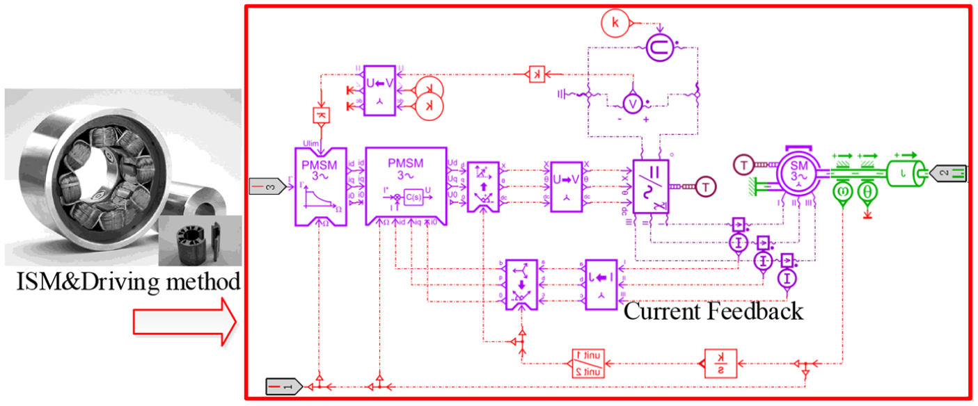
Simulation model of the vector control part in ISM.
Simulation model of PRS
To analyse the effects of the friction and backlash inside PRS on the system performance, a simulation model was developed on the basis of the analysis of motion mode and stress status of PRS. The thread direction of PRS used in this article was the right-hand side. The left rotation of the screw and the upward motion of the nut were determined as the positive directions. I-axis and J-axis were identified to be normal and parallel to the thread surface, respectively. Then, comparative analysis was performed via combining the motion systems of the nut and screw. The directions of the friction Ff and the converse thrust FN on the thread of screw are shown in Figure 12.

Theoretical model of PRS.
The sum of speed values on the I-axis and J-axis are, respectively, given as

where
Figure 13 illustrates the simulation model of PRS in AMESim on the basis of theoretical analysis. The top part is the backlash and stiffness model of PRS built on the I-axis and the bottom part is the friction model built on the J-axis.
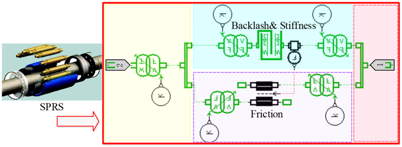
Simulation model of PRS.
Simulation model of position servo system
Due to the capability of eliminating the steady-state error of slope signal and the phase lagging of the sinusoidal signal, it was considered to compensate the feedforward control prior to the occurrence of system deviation, thus improving the response rate of the system. 31 Therefore, the feedforward control was added in the system to improve its rapidity and stability. At the same time, the three-loop PID controller is used to correct the residual error, which can constrain the motor speed and acceleration while satisfying the fast and high-precision positioning, thus enhancing the robustness of the control system and the stability and dynamic properties of the entire system.
On the basis of the previous analysis, sensors were inserted into the proper positions considering the equivalent mass of the structures, moment of inertia, stiffness, loading mode and the stiffness of the joint between the shell and force sensor inside the system. The simulation model of the system was developed in AMESim, as demonstrated in Figure 14.
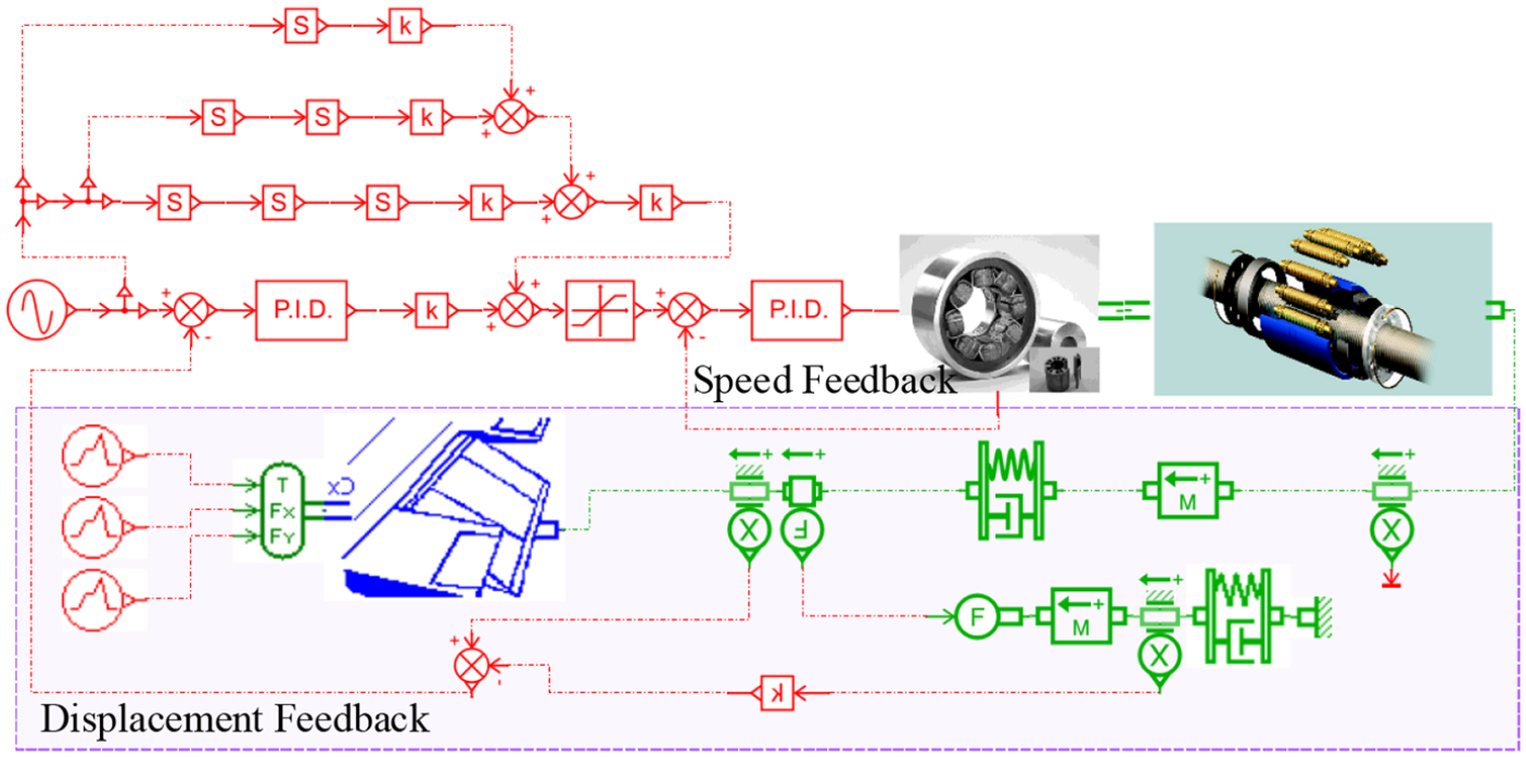
Simulation model of position servo system.
Simulation analysis of the dynamic response of IEMA
This section mainly presents analysis regarding the dynamic behaviour of the system on the basis of the mathematical and simulation models. High bandwidth, which is closely related to the gain and phase margin, can provide a higher response speed of the control surface on the aircraft, thus achieving higher flight envelope. In addition, maintaining the gain and phase margin can increase the resistance to perturbance from both inside and outside. These two characters are affected by the backlash, friction and stiffness of the IEMA system. Therefore, it is necessary to investigate the effects of these parameters on the dynamic properties of the system to provide the possible solutions.
Simulation of step response
The computing time and sampling frequency were set as 10 s and 10,000 Hz, respectively. A step instruction signal with 0.03 m was given to the system amplitude at 1 s. Subsequently, a 5-kN external instantaneous impact was applied on the wing surface at 5 s. By adjusting the parameters of control system, the displacement curves of the system and the rotating speed curve of the motor are shown in Figure 15. It was observed that the step response of the system had a fast rate combined with low rise time. Neither overshoot nor steady-state error was indicated. Only small oscillation was observed for the rotating speed and output displacement of the motor when given an external perturbance input. In addition, this oscillation had a tiny output displacement variation and was diminished quickly. All these findings indicate that the system has strong resistance to external perturbance and high robustness.
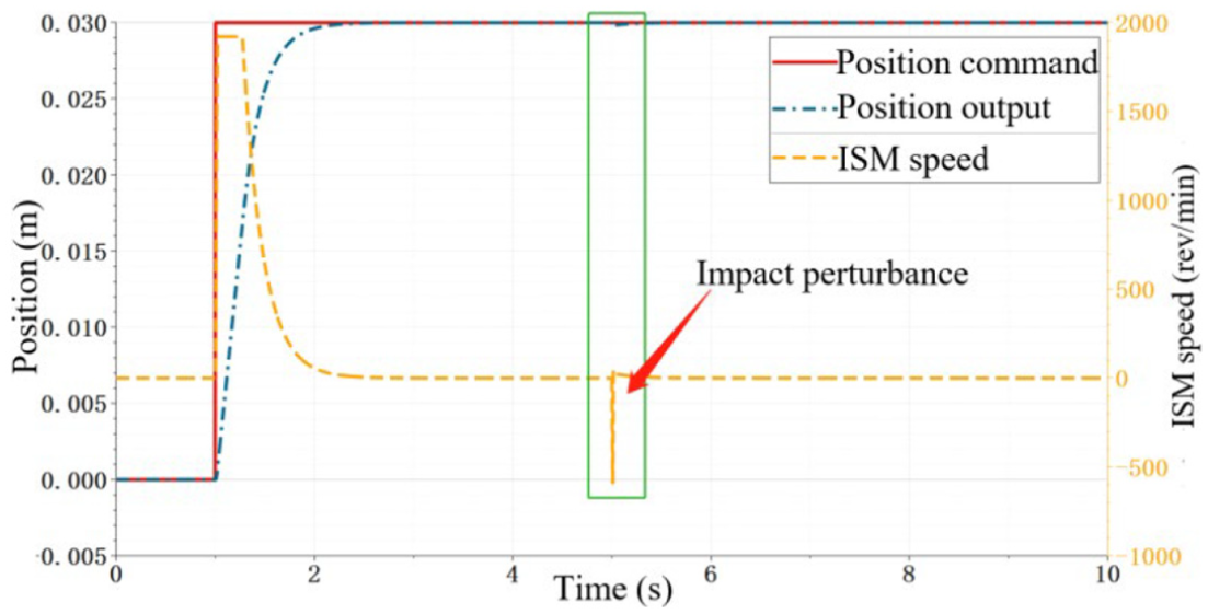
Step response curves.
Simulation of sinusoidal response
The computing time and sampling frequency were set as 10 s and 10,000 Hz, respectively. The sinusoidal instruction signal was given with amplitude of ±1.5 mm and frequency of 5 Hz. By adjusting the parameters of the control system, the response curves were obtained, as shown in Figure 16. It can be seen from the figure that the system had a rapid sinusoidal response combined with a relatively low phase lag but no amplitude reduction. The motor quickly reached the maximum rotating speed after the IEMA was initiated.
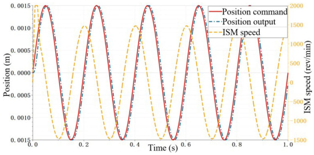
Sinusoidal response curves at 5 Hz.
An analytical study was conducted for the sinusoidal response characteristics of the system under the condition of 0–9 Hz frequency combined with a ±1.5 mm amplitude. The results indicated that the system showed an increased phase lag combined with an amplitude reduction phenomenon when increasing the sweep frequency. From 7.5 Hz onwards, as the frequency increases, the amplitude abruptly decays and the phase lag increases rapidly. Based on the analysis of the curves, it can be indicated that the maximum rotating velocity, rather than the peak values of power or current, was the limitation for the frequency response of the position of the closed-loop system. Therefore, to further improve the dynamic properties of the system, it is suggested to properly increase the rotating velocity of the ISM or the lead of the screw.
Effects of nonlinear transmission backlash on the system performance
It is unavoidable to have transmission backlash in the mechanical transmission systems due to error during the manufacturing and installing process and wear during the working process. This backlash results in a ‘dead zone’ during input and output processes combined with static friction. The latter introduces the phase lag, which finally results in a reduction in the gain margin, phase margin and bandwidth. Therefore, even a small ‘dead zone’ can be a crucial limitation for the output speed and locating control accuracy of the entire system.
The backlash existing in the transmission and joints in IEMA will not only create errors in the output location when changing the actuating direction, but also influence the safety and robustness of the entire system. The nonlinear model for the backlash can be clarified as the Physical Model, Phase Plane Model, Rubber Model and Dead Zone Model. When given a low or zero damping on the rotation shaft, the demonstration of backlash using the Dead Zone Model is very close to the real condition. Therefore, this model was selected in this article to analyse the backlash in IEMA, as shown in Figure 17. 32

Dead zone model.
Once the transmission system was staying the dead zone, there was no motion for the output bar, regardless of the clockwise or anticlockwise rotation of the motor. The output bar was actuated together with the driving end only when it was not in the dead zone. For instance, the output bar will stop for a short time and start to move again once the motor in IEMA changes the rotating direction. This is the effect of the dead zone. The torque transmission relationship between the driving and the driven parts is described as

where k is the torsional stiffness of the transmission axis, θ(t) is the relative rotation angle between the driving axis and the loading end, and α and 2α are the backlash at single side and the sum of backlash, respectively.
Owing to the small backlash values provided by the adopted PRS, the setting backlash values were defined as 0.0001, 0.001, 0.0025 and 0.005 mm, respectively, to gain further insight into their effects on the system performance. The other parameters were kept constant. The triangular-slope instruction was set as the input displacement instruction combined with a computing time of 5 s and a sampling frequency of 10,000 Hz. The curves of input and output displacements and of motor rotating velocity are depicted in Figure 18. In order to analyse the effects on the system performance, the parts of the output displacement curve at 3 s, that is, the moment when the motion direction of the system was changed, were enlarged. Only small oscillations were found on the output rotating velocity of the motor when the motion direction was changed, implying a good tracking performance of the integrated control system. This can also be found from the enlarged displacement response curves; the output displacement presented plateaus at the peaks. In addition, with the increase of the backlash value, the plateaus were becoming wider and the dynamic performance was becoming lower.
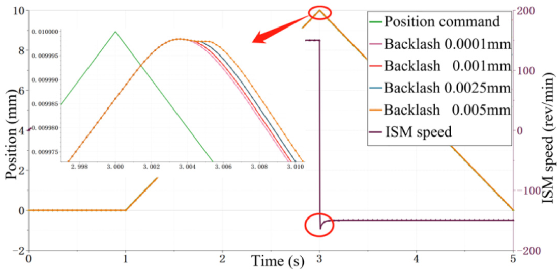
Effects of backlash on the system performance.
This dead zone phenomenon will limit the velocity and position control accuracy of the IEMA. Moreover, the oscillation of the motor will directly influence the driving and transmission parts, which finally results in accelerated damage within these parts combined with vibration and noise, thus decreasing the safety and robustness. Therefore, it is crucial to minimize the effects of the backlash on the system dynamic behaviour. According to the open literature, the methods adopted in this article are listed as follows:
Fastening the gear structure using the spring loading devices: for instance, the preload was applied on the PRS and transmission parts while an anti-backlash gear structure was used in the reducer. This was not a problem for IEMA. In this strategy, a radial force was applied to the gear structure to minimize the backlash.33,34 On the other hand, it should be noted that the friction would be increased by the evolution of preload, which resulted in a limitation effect on the system properties. Therefore, this strategy only provides a balanced solution between the backlash and friction, but does not completely solve the ‘dead zone’ problem.
Applying soft materials to fill the transmission parts to minimize the backlash: however, soft materials will introduce spring effects, reducing the system stiffness. Additionally, the friction will be enhanced. Therefore, it is also regarded as a balanced solution. 35
Diminishing the wear during the working process by improving the accuracy of machining and manufacturing combined with the usage of anti-wear materials. This action can also increase the life cycle and robustness of the entire system.
Providing a compensation for the backlash using proper control strategy: for instance, the methods for estimating or measuring the width of the dead zone, such as the feedforward self-adjusting, neural network and fuzzy control.36,37
Effects of nonlinear friction on the system performance
As one of the most critical obstacles for high-accuracy locating, friction is always unavoidable during the mechanical transmission process. It will lead to steady-state error and tracking deviation, which decreases the system efficiency. Moreover, friction is one of the key factors to affect the low-velocity motion and reverse motion of the system. 38
Due to the difficulties in conducting an individual analysis on the friction behaviour of each part of the system, an equivalent friction of PRS was adopted to perform the simulation investigation. As indicated in Figure 19, there are many types of friction models, for example the classical friction model formed by static friction, Coulomb friction and Viscous friction. It is found that the friction will show a continuous decrease, rather than a step-like one, during the initiation of sliding. Therefore, a more comprehensive Stribeck friction model can be obtained based on the three models mentioned above, whose friction torque equation is expressed as follows39–41

where Tc and Kvω are friction torque in Coulomb and Viscous theory, respectively. Ts is the maximum static friction and ωs is the critical Stribeck velocity, which determines the shape of the Stribeck curve combined with the parameter δ.
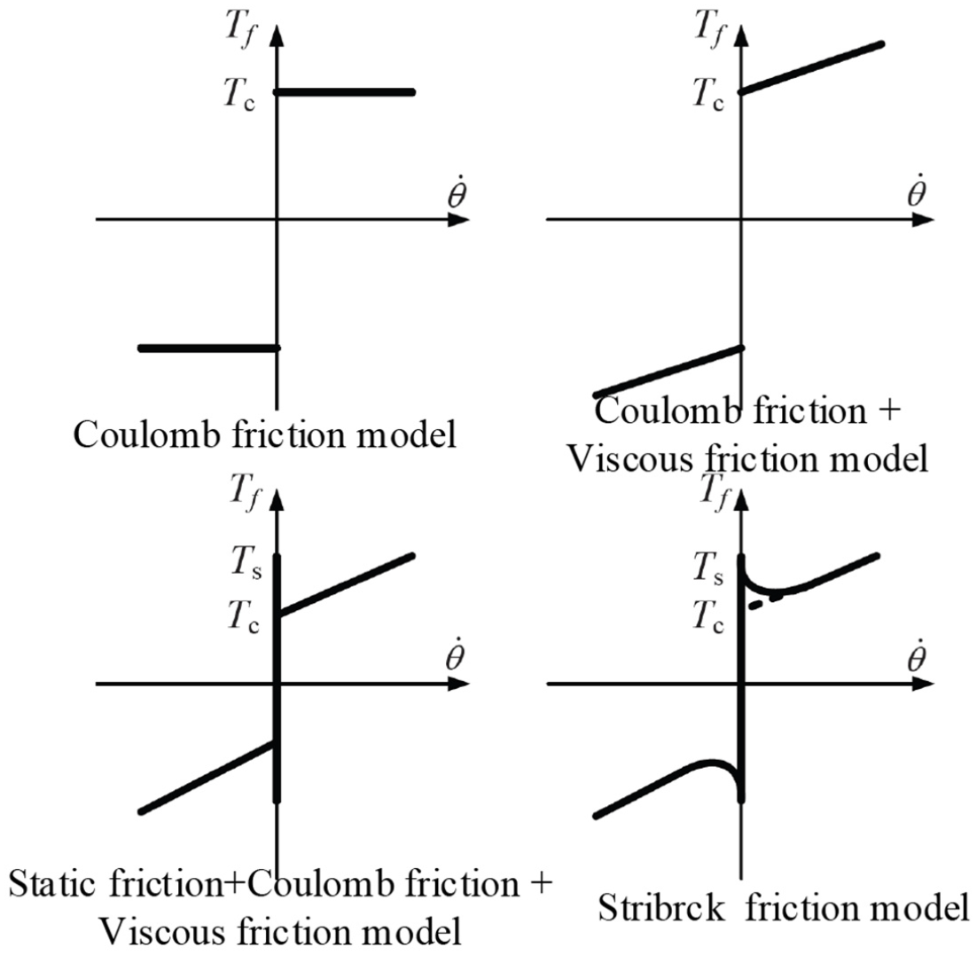
Classical friction models.
In order to explore the effects of transmission friction on the dynamic properties of the IEMA system, rotating friction pairs were applied to the simulation model. Considering the effects of different system friction on the system properties, the influence from the backlash was neglected in this section. Maintaining the other parameters constant, the friction coefficients were set as 0.01, 0.03, 0.05, 0.07 and 0.09 during the simulation. First, a comparative analysis was performed regarding the step response under the condition of different friction coefficients. The step instruction at 0.5 s was identified as 0.03 mm, combined with a computing time of 2 s and a sampling frequency of 10,000 Hz. The input and output displacement curves were obtained as shown in Figure 20. After that, a comparative study was conducted on the sinusoidal response under different friction coefficients. The amplitude and frequency were set as ±1.5 mm and 5 Hz, respectively. Computing time and sampling frequency were the same as the values mentioned above. The input and output displacement curves are as shown in Figure 21.
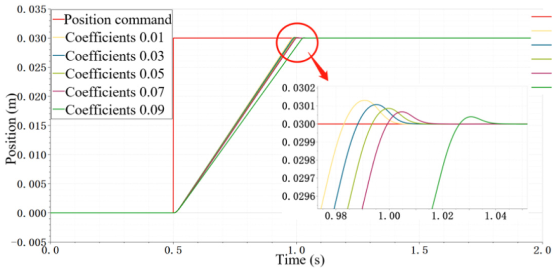
Comparison of the step response curves of the system under different friction coefficients.

Comparison of sinusoidal step response curves of the system under different friction coefficients.
It can be manifested from Figure 20 that the response speed, vibration amplitude and adjusting time are different when given different friction coefficients. The response speed, amplitude and adjusting time were, respectively, becoming lower, smaller and longer with increase in the friction coefficient. As depicted in Figure 21, the input instruction can be almost completely realized without any phase lag using the integrated control strategy. Nevertheless, a difference in reduction magnitude was found in the system sinusoidal response under different friction coefficients. Specifically, as the friction coefficient of the system increases, the amplitude attenuation becomes larger and the tracking performance deteriorates.
However, it should be noted that friction is always existent during the mechanical transmission process. To minimize its effects on both the dynamic and static properties of the system, it is suggested to use materials with lower friction resistance on the machine and to improve the lubrication technique or provide for a compensation using a controller.
Effects of system stiffness on the system performance
The system stiffness includes structural stiffness and joint stiffness. The effects of stiffness on the system properties can be neglected if the system stiffness exceeds a threshold. 42 However, specifically for the IEMA developed in this article, the volume and weight should be minimized while maintaining the qualified dynamic properties. Because the system stiffness will be influenced with the reduction of volume and the weight of IEMA, this section mainly presents an investigation on the effects of system stiffness.
The material selected for PRS in this research was GCr15 bearing steel with a constant size and stiffness. Since both the structural parts and the joints of the IEMA system were lying in the axial direction, the stiffness of both the parts can be regarded as an equivalent value, denoted as system stiffness, according to the superposition principle of spring. The system stiffness values were set as 1 × 10⁶ N/m, 5 × 10⁶ N/m, 1 × 10⁷ N/m, 5 × 10⁷ N/m and 1 × 10⁸ N/m during simulation analysis. A comparative analysis was first performed on the step response under different stiffness conditions. The step instruction at 0.5 s was identified as 0.03 mm combined with a computing time of 2 s and a sampling frequency of 10,000 Hz. The input and output displacement curves were obtained, as shown in Figure 22. Subsequently, a comparative study was conducted on the sinusoidal response under different stiffness conditions. The amplitude and frequency were set as ±1.5 mm and 5 Hz, respectively. The input and output displacement curves are indicated in Figure 23.
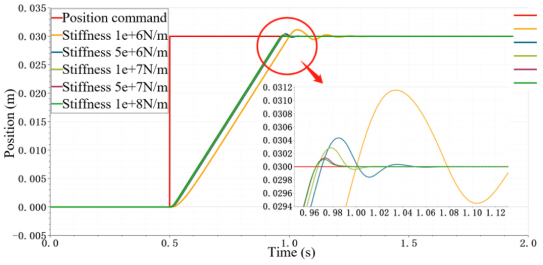
Comparison of the step response curves of the system under different system stiffnesses.

Comparison of the sinusoidal response curves of the system under different system stiffnesses.
It can be clearly observed from Figure 22 that the vibration amplitude and adjusting time increase with increase in the system stiffness, exhibiting a peak value once the stiffness is around 5 × 10⁷ N/m. From this point onwards, the performance cannot be further optimized by increasing the stiffness. Based on the observation in Figure 23, the input instruction can be almost completely realized without any phase lag using the integrated control strategy. However, the resonance peak decreased with the evolution of system stiffness. There was no indication of resonance once the stiffness reached 5 × 10⁷ N/m. The details are listed in Table 3.
Correlation between system performance index and system stiffness.
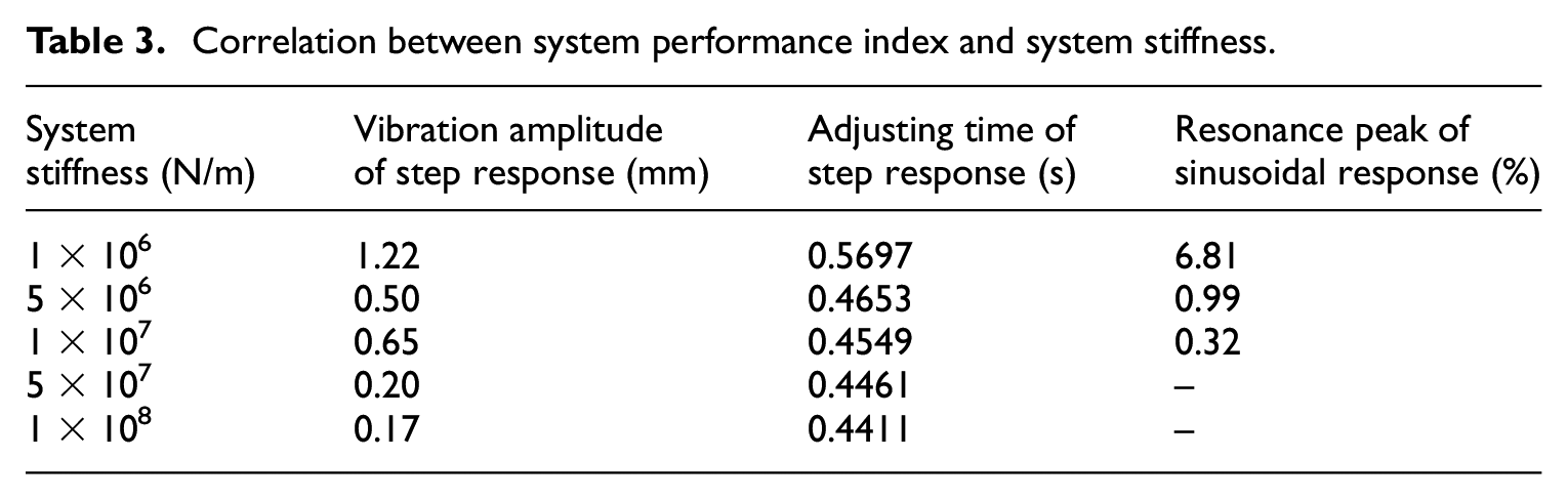
Therefore, considering the system volume, weight and dynamic properties under the condition of system space optimization, the system stiffness should be set as around 5 × 10⁷ N/M in the optimization design stage.
Test system and result analysis
On the basis of the model and simulation investigations in the previous sections, this section presents a series of experimental studies on the IEMA research prototype through a self-developed test system. The main parameters are listed in Table 4. The research contents mainly include the step response tests, sinusoidal response tests, repeat locating accuracy tests and resolution tests of the IEMA system.
Main parameters and corresponding values.
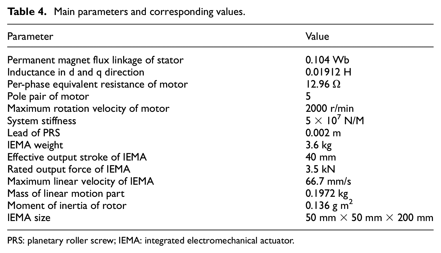
PRS: planetary roller screw; IEMA: integrated electromechanical actuator.
Test system
The test platform developed in this article mainly consisted of supporting bases numbered from 1 to 5, a linear spring, a grating scale, a tension-compression sensor and an IEMA research prototype (Figure 24). The supporting base provided support for the unloading process in the axial direction of the system. The grating scale was used to directly measure the axial displacement values of the output end in IEMA. The tension-compression sensor was used to measure the axial load of the system. The rotating transformer was installed inside the IEMA to complete the position of the closed-loop control.
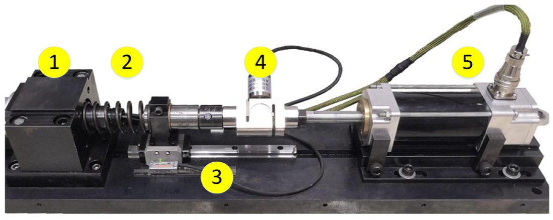
Photograph of the test platform of IEMA research prototype.
The control system was mainly used for data processing, parameter setting, algorithm controlling and data acquisition. The working mechanism of the control system and its photograph are shown in Figure 25. Once initiated, the host computer sent instructions and drove the IEMA through the corresponding driving circuit. Feedback signals sent from the sensors was captured by the data acquisition card after processing and was transferred from A/D to D/A inside the card. After data processing and calculation, the position closed-loop control to IEMA can be realized. The entire control system was designed as a cabinet, consisting of an industrial control computer, a monitor, an adaptation box and an electric power box.

Schematic diagram and photograph of the control system.
Step response tests
1. The step response tests were performed without applying load. The step instructions with amplitude values of 10, 20 and 30 mm, respectively, were given to the control system. The comparison of the data gathered from the tests and the simulation results is summarized in Table 5. It can be found that the experimental data has good consistency with the simulation one, indicating good accuracy of the simulation model. Therefore, it can be directly used to analyse the system performance of IEMA.
Comparison of the test and simulation results of the system step response.

Figure 26 illustrates the comparison of the test and simulation results at the 30-mm step instruction. The voltage rapidly increases to the maximum value after receiving the step instruction, providing a possibility for the fast system response. The adjusting time of both curves obtained from tests and simulation were lower than 0.5 s without overshoot. The reason for the tiny lags and oscillations approaching the terminal end of the tests was caused by the nonlinearity of the real system, which was an important reference for further optimization on the simulation model.
2. Step response tests were performed under linear loading condition. Linear springs with a 70-N/mm stiffness coefficient were installed at the end of the IEMA system. A load magnitude of 2100 N can be provided given a 30-mm compressive displacement. Taking the step instruction with a 30-mm amplitude from the control system as an example, the comparison of the test results obtained with and without load is plotted in Figure 27. It can be seen that the rising time and stable time were almost the same in both the conditions, implying good performance of the system and control strategy.

Comparison of the system step response (30 mm) between the test and simulation results.

Comparison of the system step response results (30 mm) obtained from tests and simulation.
Sinusoidal response tests
The sinusoidal response tests were performed without applying load. Sinusoidal signals with an amplitude of 1.5 mm combined with frequency of 1, 3, 5, 7 and 7.5 Hz were successively input into the control system. The amplitude reduction and phase lag values were recorded. The comparison results are listed in Table 6.
Comparison of the data obtained from the sinusoidal response tests and simulation analysis of the position servo system.

When the sinusoidal response frequency was higher than 5 Hz, amplitude reduction and phase lag were found in both the test and simulation results. This was a consequence of the limitation from the motor rotating velocity. The relationship among the system output displacement, time and frequency can be expressed as

The system output velocity is the derivative of the output displacement

where A and f are the sweep amplitude and frequency with units of mm and Hz, respectively.
The maximum rotating velocity of the ISM in the designed IEMA in this article was 2000 r/min. Accordingly, the theoretically calculated maximum linear output velocity of IEMA is given as

Based on the calculation, the system amplitude would not be reduced within the maximum motor rotating velocity. Therefore, the maximum frequency value (7.07 Hz) of the instruction signal could be completely realized, which was consistent with the simulation results. However, due to the nonlinear friction and damping existing in the real system, the practical performance was slightly lower than the simulation. Therefore, it is suggested to properly increase the rotating velocity of the ISM or improve the lead of PRS to achieve further improvement in the dynamic behaviour of the system.
Repeat locating accuracy tests
Tests were performed to evaluate the repeat locating accuracy of IEMA. A complete round trip between 0 and 30 mm was considered as a full cycle for the repeat position accuracy test. Using the grating scales, the results obtained from multiple measurement indicated that the repeat locating error for the IEMA system within the whole stroke was not higher than 10 μm. This value included control error, sensor error, fastening backlash, axial screw backlash and so on.
Resolution tests
The resolution of the IEMA system is the minimum step value and can be identified and obtained by the system. During the tests, the step instruction was continuously decreased from 0.1 mm until the motion of the output bar cannot be measured by the grating scale. The minimum resolution for the IEMA was obtained as 0.5 μm.
This section mainly develops an IEMA research prototype combined with the related test system based on the previous research, providing experimental validation for the simulation results. According to the results obtained from the step response tests, sinusoidal response tests and repeat locating accuracy tests for the IEMA, it can be indicated that the IEMA system exhibits good capabilities regarding tracking capability, accuracy, stability and rapidity.
Conclusion
In this article, a series of studies were performed on IEMA regarding the integrated design, analytical and simulation modelling and experimental tests. The related conclusions are drawn as follows:
According to different integration methods, three integrated design strategies for the IEMA were proposed. Detailed demonstration was performed regarding the specific structures and component selection for all the strategies. The categories and properties of PRS, which was the key part of IEMA, were comparatively analysed. In addition, taking the actuator of the control surface driving system in a certain type of aircraft as reference, a specific IEMA system was proposed with a detailed introduction of the structural design strategies.
A mathematical and a simulation model were developed on the basis of the structural design. The system transfer functions of the IEMA were deduced according to the working mechanisms and joining configurations of each component. The system stability within the entire frequency field was analysed via the mathematical model. Based on the mathematical model, the simulation model of key units and the IEMA system were established using AMESim. The effects of friction, backlash and stiffness on the dynamic behaviour of the system were discussed and the related solutions were provided, which offer great values for the further research on IEMA.
An IEMA research prototype combined with the test system was developed and a series of tests were performed. The experimental results obtained from the step response tests, sinusoidal response tests and repeat locating accuracy tests indicate good capabilities, such as tracking ability, accuracy, stability and rapidity, of the developed IEMA system.
Footnotes
Declaration of conflicting interests
The author(s) declared no potential conflicts of interest with respect to the research, authorship and/or publication of this article.
Funding
The author(s) received no financial support for the research, authorship and/or publication of this article.