
Abstract
This work presents a novel integrated device that combines a hybrid stepping motor (HSM) and a planetary gear train (PGT) reducer as a compact structural assembly. In this study, a systematic design process was developed to efficiently implement the integrated device. By applying the gear profile on the rotor and the stator, a 9:1 two stages PGT reducer is integrated with a standard 42 type 2-pole stepping motor. The quadratic interpolation method was applied to derive the optimal design of the geometric configurations of the HSM. The electromagnetic characteristics and output performance of the integrated device, including flux linkage, back-emf constant, holding torque, and output torque, were analysed. Finally, the output performance between an existing design and the novel integrated design were compared. The two designs had similar output and holding torque, but the torque ripple was approximately 44.7% lower in the integrated device from 30% to 16.6%. In addition, the axial space arrangement was reduced by 5.2% from 67.7mm to 64.1 5mm, and the torque density was improved by 4.4%.
Keywords
Introduction
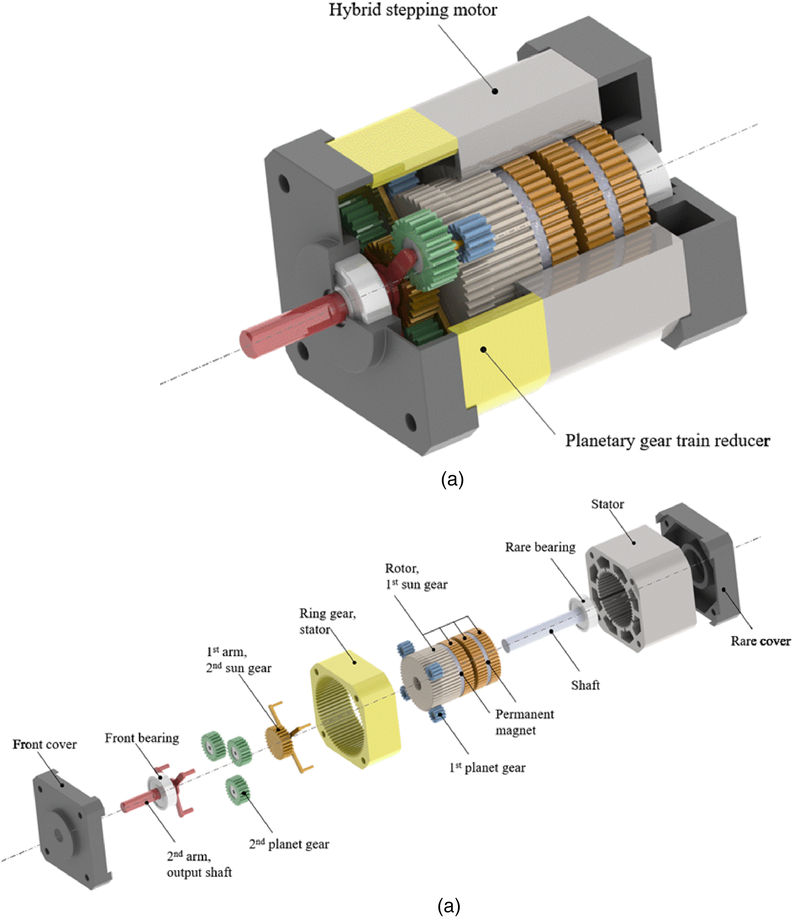
Stepping motors are widely used in machinery because of their straightforward and precise position control and high torque density at low speeds. Nevertheless, their performance is considerably affected by their working load conditions. Step loss can occur if the load exceeds the motor's maximum output capacity. In general, electric motors are usually combined with gear reducers to provide the desired power output with the highest efficiency. However, motors and reducers are designed and manufactured independently, which causes several disadvantages, such as redundancy in the use of mechanical elements, long power transmitting paths, extra power loss, and incompact arrangement. Accordingly, an integrated device, as shown in Figure 1, eliminates coupling and directly combines the electric motor and the gear reducer, thereby not only overcoming these disadvantages but also improving motor performance.

The concept of the integrated device.
Research on improving motor performance has mainly focused on electrical methods, such as designing new control methods,1–4 or mechanical methods, such as designing new motor configurations.5–8 In 2001, a novel integrated design was proposed; this design is based on the concept that motors can provide smooth output torque even if the stator is not fixed but maintain a constant relative rotation speed to the rotor. 9 In 2006, a novel design that integrate a brushless DC motor and a planetary gear train (PGT) has been proposed. By integrating the stator and the ring gear of the PGT, the cogging torque and the torque ripple of the motor were reduced.10,11 Thereafter, based on the integrated design concept, several novel designs that integrate electric motors with an embedded PGT have been proposed.12–14 To the author's knowledge, there is no other work to integrated the hybrid stepping motor (HSM) and a PGT reducer. In this paper, the concept is applied to HSM which is a different motor type to see the electromagnetic performance and also mechanical performance.
This work introduces an innovative concept. In this research, an integrated design process was developed for integrating a HSM and a PGT reducer. This paper details the design process and subsequently introduces the main integrated design concept and features of the integrated device. Next, a discussion is presented regarding the configuration design, gear profile design, reduction ratio design, and gear strength design of the PGT. With the aid of finite element analysis (FEA), the quadratic interpolation method was used on the optimal design of the rotor and stator teeth geometric configurations of the integrated device. Subsequently, the electromagnetic characteristics and output performance of the integrated device were investigated. Finally, a feasible integrated device that eliminates the inherent disadvantages of the traditional device was obtained.
Design concept
Regarding the design process, a conceptual design is indispensable. Based on an appropriate design process, feasible designs can be synthesized. In addition, thoroughly studying conventional designs can also bring about new design concepts. Therefore, in order to obtain feasible design configurations, it is necessary to analyse the characteristics of motors and gear trains, respectively. This chapter introduces the basic mechanisms and kinematic characteristics of motors and gear trains. In addition, feasible configurations are identified. This paper proposes a design procedure for the systematic generation of integrated devices, with the motors and gear reducers being integrated in an efficient manner. Electric motors and gearboxes are widely used in various power and transmission applications. The traditional approach is to design electric motors and gearboxes independently and then integrate them after manufacturing. By using connecting components, electric motors and gearboxes can operate in the most efficient states and thus meet the requirements of a reduction in speed or an increase in torque. However, there are several disadvantages to existing designs, especially the long power transmission path. This causes mechanical loss, and it is also the source of failure and noise. In addition, such a design has extra fixed components, such as the screws or fasteners used to connect the motors and gearboxes. Since these two devices are designed independently, it is difficult to have a compact arrangement of all the components, especially the axial length. The main approach to overcoming these disadvantages is to share a designated part by combining the electric motors and gear mechanisms, without the use of extra transmission elements. The shared part is not only the shaft (as the common solutions) but the magnet rotor/stator that have both transmission and magnetic functions. And, there are also benefit of the present solution that the electromagnetic field will change, that the gear shape on the rotor/stator will be treat as dummy slots that can reduce the cogging torque.
This section summarizes the design requirements and constraints that the new design should encompass from both structural and functional viewpoints. Subject to the design requirements and constraints, feasible design concepts are developed by combining one of the HSM and a PGT reducer.
Design procedure
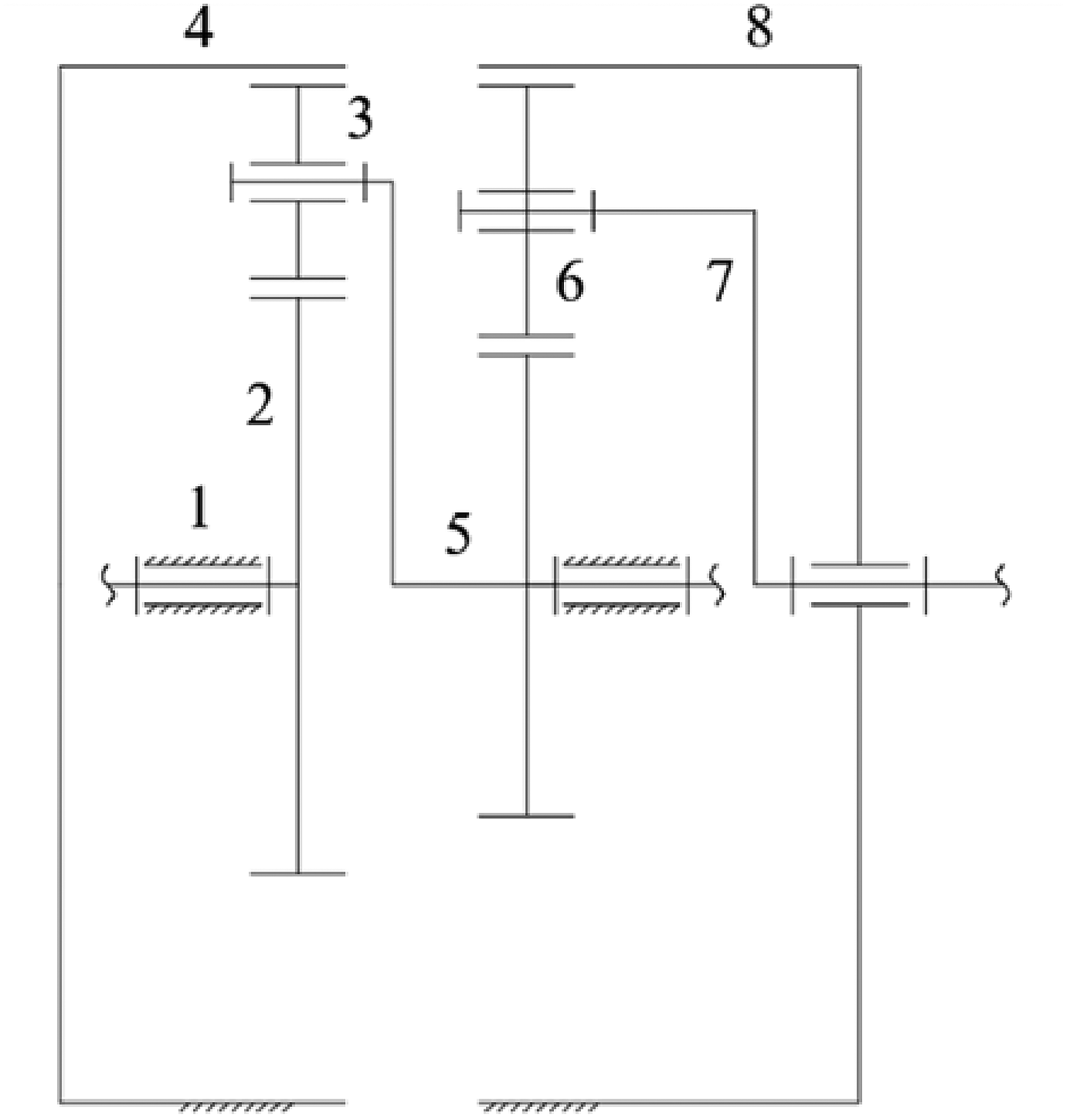
To develop an innovative integrated device that efficiently integrates an HSM and a PGT reducer, this study proposes a systematic design procedure (Figure 2), which includes the following seven steps.
Design specifications play a significant role in the design process. Designers can set the corresponding design specifications according to the requirements of the integrated device, such as input conditions, materials, and spatial constraints. The design of the HSM contains countless design parameters. For simplicity, parameters having little influence on the design objective were treated as fixed values. Because the main integrated design concept was to combine the elements of an HSM and a PGT, the selection of the integrated elements determined the configuration of the integrated device. According to HSM characteristics and the design requirements and constraints determined in Step 1, an integrated element sharing the HSM rotor and sun gear of an PGT was selected. After the selection of the integrated element, the gear profile that integrates on the rotor pole was established regarding the modulus, pressure angle, and number of teeth. In this study, the standard full-depth tooth involute spur gear profile with a 25° pressure angle, modulus of 0.5, and 50 teeth was applied. In this step, a feasible PGT reducer was developed according to design requirements and working space restrictions. During the process of designing the reducer, the configuration, gear profile, reduction ratio, and gear strength were carefully evaluated to ensure that they met the design specifications. If they did not, then the previous design step was repeated. The electromagnetic characteristics directly determine the motor's output performance. The electromagnetic characteristics are controlled by various parameters, such as magnetic materials and rotor and stator geometrics. Therefore, detailed design and analysis of the HSM were conducted. After completion of the above steps, a feasible integrated device was obtained.

Flow diagram of the design process.
Detailed explanations and results of each step are presented in the subsequent subsections.
Design specifications and fixed parameters
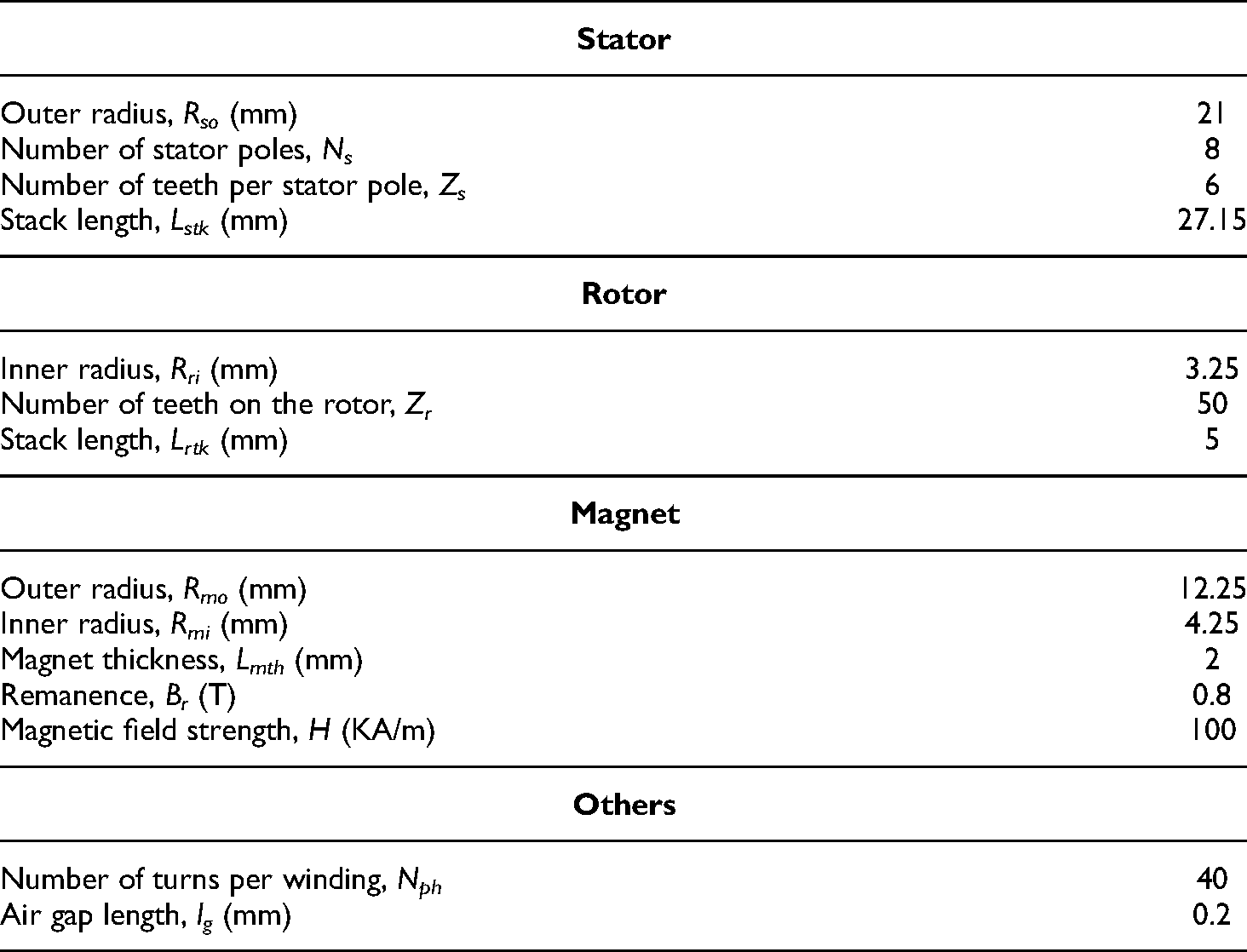
Design specifications for the integrated device include its rated input conditions, drive mode, stepping angle, and material properties. A two-phase HSM with type no. DST42EM61A manufactured by TECO electro device company in Taiwan is used as an example; Table 1 presents the design specifications of this motor. Figures 3 and 4 illustrate the geometrical dimensions of the motor(where A in Figure 3 is 39mm), and Figure 5 presents the ideal input current in this simulation.

Dimensions of the stepping motor. 15

Detailed dimensions of the stepping motor.

Ideal input current.
Design specifications.

For simplicity, the parameters presented in Table 2 were chosen as fixed parameters and assigned fixed values. The remaining parameters could be designed further. However, these fixed parameters could be adjusted if the design objectives were difficult to achieve using the set values.
Fixed parameters.
A preliminary idea was developed for deriving the innovative integrated device, which is indispensable during the conceptual design process. Analysis of the existing design can inspire an innovative design concept.
Conceptual design
Design requirements and constraints
According to the kinematic structural characteristics of a basic PGT, three coaxial links can be assigned to the fixed, input, and output links to provide a constant speed ratio. Therefore, these links must connect to the rotor, output shaft, and frame of the HSM respectively for transmitting motions. Moreover, to minimize the manufacturing cost, the integrated device should not contain any mechanisms other than the HSM and PGT. The design requirements are summarized as follows:
The input link of the PGT must be connected to the HSM rotor. The fixed link of the PGT must be connected to the HSM stator. The output link of the PGT must be combined with the output shaft of the integrated device. The rotor pole's profile of the HSM should be replaced by the gear profile.
The design constraints are summarized as follows:
As the sun gear of the basic PGT is the input link, it is more suitably integrated with the HSM rotor. As the ring gear of the basic PGT is the fixed link, it is more suitably integrated with the HSM stator. To simplify the design process, the gear teeth integrated with the rotor are of the exterior type and on the stator are of the interior type. To keep the air gap length, the stator's geometric profile should be redesigned after integration of the gear with the rotor. For transmission stability, more than two planet gears must be used in the PGT reducer.
Selection of the integrated element
In this study, the design concept aims to integrate an HSM and a PGT reducer to achieve a simpler and more compact device with a higher working efficiency. Because the HSM rotor and gear have a pole-like structure, the HSM rotor and sun gear of the PGT were selected as the shared element. The rotor pole's profile of the HSM needed to be replaced by the gear profile.
Identification of the integrated gear profile
After the selection of the integrated element, the gear profile that replaces the original rotor pole's profile should be identified, including its gear type, modulus, number of teeth, and pressure angle. To allow the integrated rotor to have transmission ability without affecting the electromagnetic characteristics of the HSM, the gear profile was restricted by the geometric limitations of the existing design. Therefore, the design constraints of the gear profile were as follows:
Because the number of rotor poles determines the step angle of the HSM, the number of teeth should be the same as the number of poles of the rotor. Because an air gap would strongly affect the HSM's electromagnetic characteristics and output performance, the addendum circle diameter of the gear must be as close as possible to the rotor's outer diameter. For simplicity and to avoid problems during manufacturing, a standard full-depth tooth involute spur gear profile with a 25° pressure angle was applied. Moreover, a commonly used modulus of a gear (JIS B 1702) was selected. The reason we choose the 25° pressure angle instead of the25° pressure angle is that the base circle diameter. The original step teeth shape is rectangle. If we use 25° pressure angle gear can easier to modified the original stamping die. Designers can choose by themselves.
According to the aforementioned design constraints, the rotor of an existing HSM with 50 poles and a 26-mm outer diameter was replaced by a standard full-depth tooth involute spur gear profile with a 25° pressure angle, modulus of 0.5, and 50 teeth. Figure 6 illustrates a cross-sectional view of the integrated design concept.

Cross-sectional view of the design concept.
Design and analysis of the PGT reducers
For the integrated device, the PGT reducer provides functions for increasing the HSM's output torque and resolution. To design a proper PGT reducer, the configuration, number of teeth, and reduction ratio should be carefully designed to achieve the desired functions, adhere to the geometric restrictions of the HSM, and provide available space for the integrated device.
Configuration and kinematic design. Because the basic PGT is a 2 degree-of-freedom mechanism, its output depends on the relative motion between three coaxial links. In this study, the sun gear is defined as the input link, the ring gear is defined as the fixed link, and the carrier is defined as the output link to achieve the highest reduction ratio and motor resolution. After the number of teeth on the sun gear has been determined, the number of teeth on the ring gear must be decided. During the process of deciding the number of teeth on the ring gear, several design constraints must be considered regarding the existing stator's geometric restrictions. The design constraints are as follows:
To guarantee smooth operation of the PGT, the difference in number of teeth between the sun gear and ring gear must be an even number to meet the concentric condition of the PGT's teeth design constraints. To achieve the maximum spatial utilization and reduction ratio, the diameter of the dedendum circle of the ring gear must be smaller than but as close as possible to the outer diameter of the stator. For simplicity and to avoid problems during manufacturing, the standard full-depth tooth involute spur gear profile with a 25° pressure angle is applied, and the modulus must be equal to that of the sun gear.
For the existing HSM with a 42-mm outer diameter of the stator, the ring gear was selected to have a standard full-depth tooth involute spur gear profile with a 25° pressure angle, modulus of 0.5, and 74 teeth. Its dedendum circle diameter is 38.25 mm. The tooth numbers of the planetary wheels are 12 and 23 teeth, respectively.
Because the geometry of the existing HSM severely restricts the number of teeth and the range of the reduction ratio of the PGT reducer, the reduction ratio of the first-stage PGT was 2.48, which caused the step angle to become difficult to use. Therefore, the second-stage PGT with a 28-tooth sun gear and 74-tooth ring gear was designed, with a total reduction ratio of approximately 9. Figure 7 presents a schematic of the PGT designed in this study. Table 3 presents the basic parameters of the integrated rotor.
PGT design.
Basic parameters of the integrated rotor.

Design and analysis of the HSM
On the basis of the design concept, the rotor tooth profile was replaced by the gear profile, necessitating a detailed investigation of the effect of the gear profile on electromagnetic characteristics. The quadratic interpolation method 16 was applied to execute the optimal design of the HSM to achieve the optimal output performance.
Electromagnetic analysis
In this study, ANSYS/Maxwell FEA software was used to analyse the electromagnetic characteristics and output performance of the HSM.17–22 Figure 8 illustrates the mesh model of the two-phase HSM. Figure 9 illustrates the flux density distribution of the HSM with the excited first-phase coils.

Mesh model.

Flux density distribution.
Quadratic interpolation method
The unique geometric configuration of the rotor and stator allows the HSM to have unusual output characteristics. Thus, improving the output performance requires the careful attention to electrical parameters and geometric configurations during the process of designing the mechatronic system. Quadratic interpolation is a useful optimal design method when the objective function is the outcome of a complex interaction between various parameters. It can be practiced without understanding the complicated relation between design parameters and the objective function, and it can make the design more systematic and efficient. This method is used for unconstrained optimization. The main concept is that any continuous function on a given interval can be approximated by a higher-order polynomial. Thus, the optimal point of the objective function can be predicted according to the extremum point of a quadratic polynomial, helping to get closer to the optimal solution.
The quadratic interpolation method was used in this study to optimize the geometric configuration of the rotor and stator. Figure 10 provides a flow chart of its computational algorithm, which includes the following six steps:
Identify the objective function and design parameters.

Computational algorithm of the quadratic interpolation method.
Average torque, holding torque, and torque ripple are the three major output properties for evaluating the HSM's quality. Thus, the objective function considers maximum holding torque, average torque, and minimum torque ripple and can be expressed as follows:
Because the tooth width/tooth pitch ratio significantly affects the HSM's output performance, the rotor tooth width/tooth pitch ratio γw was selected as a design parameter in this study. However, the tooth profile is altered by the fixed gear profile. Therefore, to adjust the tooth width/tooth pitch ratio without costing the device its transmission ability, the gear tooth (only the part inside the motor) was shortened. Next, the stator inner diameter was redesigned to ensure that the air gap length was the same as that in the existing design. The expanded angle of the stator pole Set the initial conditions and convergence criteria.
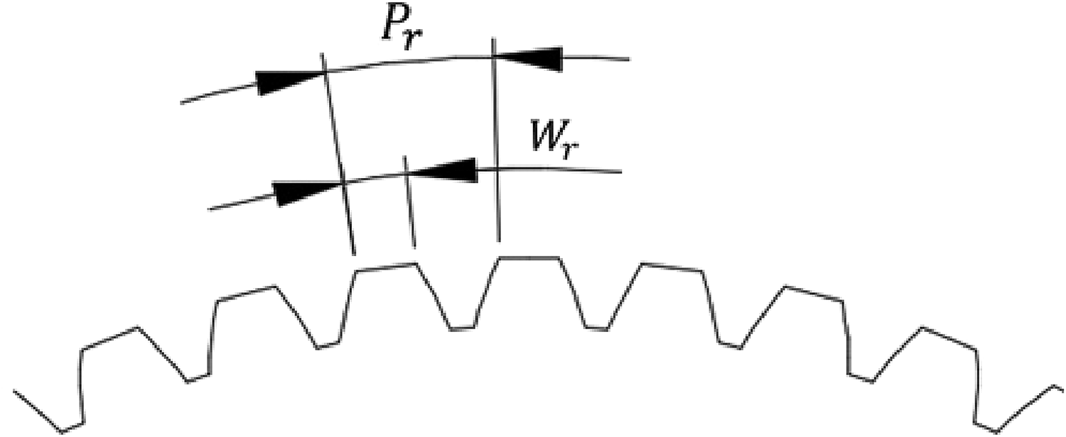
Rotor tooth width and tooth pitch .

Expanded angle of the stator.
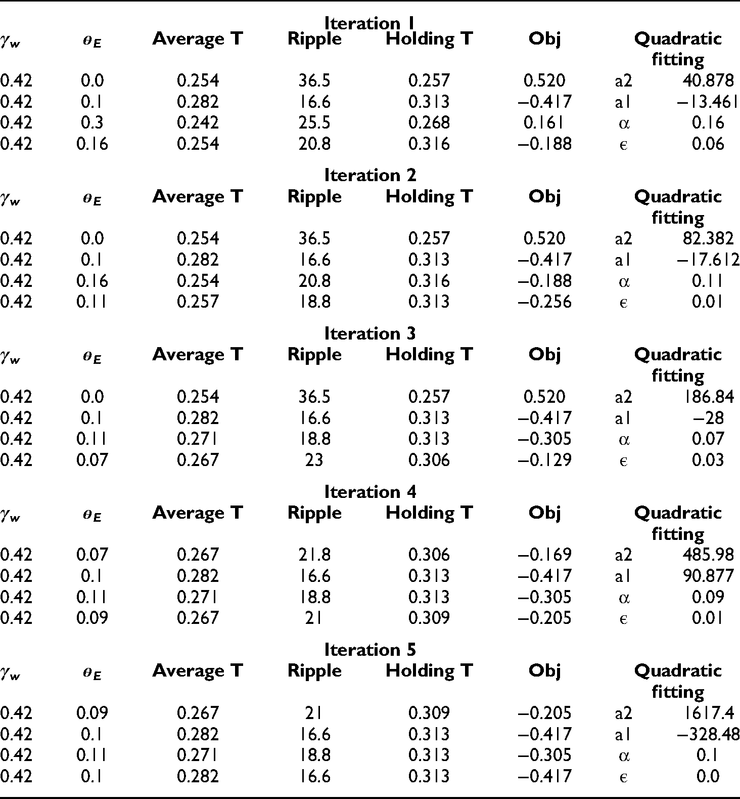
An HSM can achieve higher torque density and lower torque ripple when γw is between 0.38 and 0.45, with the optimal value of 0.42.
4
Therefore, the lower bound αl and upper bound αu of the initial interval were set as 0.38 and 0.45, respectively, and the intermediate point αi was 0.42. For Calculate the function value of the initial interval and intermediate point. Calculate the approximate quadratic function and its extremum point. Refine the interval and intermediate point. Check the convergence criterion.
After analysis of the initial interval and intermediate point, the corresponding objective function values of αu, αl, and αi were 0.708, − 0.417, and − 0.098, respectively.
Any quadratic function can be expressed in the following general form:
For the subsequent iteration, the interval and intermediate point were refined. Before refinement, the values of the intermediate and extremum points and their function values should be compared first to determine the new interval and new intermediate point. Because the extremum point is smaller than the intermediate point and its function value is greater than that of the intermediate point, the new intermediate point and upper bound remain the same, and the extremum point replaces the lower bound.
Iterations continue until the convergence criterion of γw (<0.001) is met.
Figures 13 and 14 present the iteration diagram of γw and

Iteration diagram of the rotor tooth width/tooth pitch ratio.

Iteration diagram of the expanded angle of the stator pole.
Results of rotor tooth width/tooth pitch ratio (γw) for each iteration.

Results of the expanded angle of the stator pole (
Comparison and discussion
The electromagnetic characteristics and output performance of the optimized integrated device were analysed and compared with those of the existing device. Figures 15 and 16 illustrate the comparison of the flux linkage and back-emf constant between the two devices, respectively. In general, after the original tooth was replaced with the gear tooth, the flux linkage and back-emf constant exhibited similar trends. However, the peak values of the integrated device were slightly lower than those of the existing design, and the period of the integrated device had a small phase lag for both the flux linkage and back-emf constant.
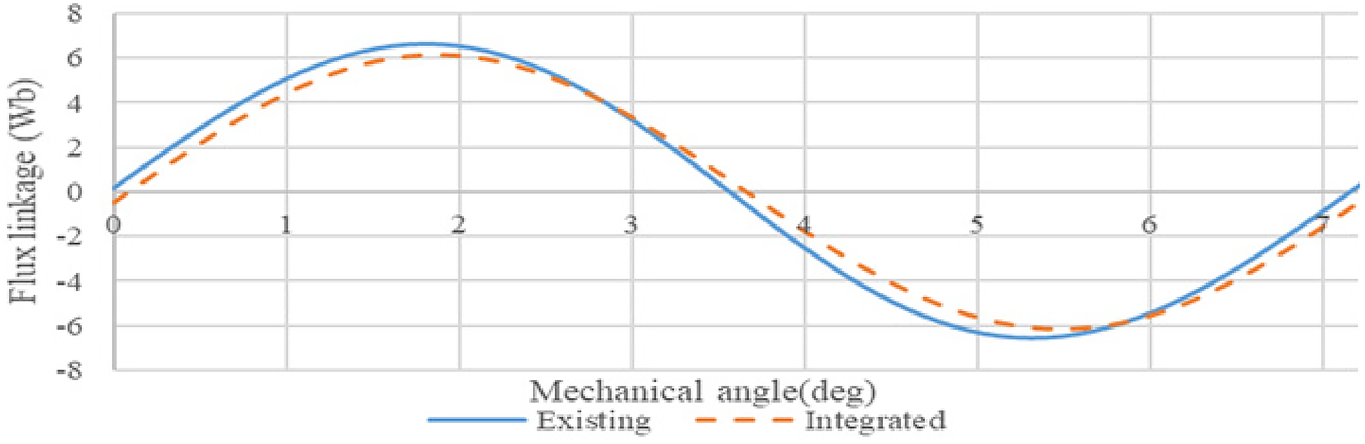
Comparison of flux linkage between the existing design and the integrated device.

Comparison of back-emf constant between the existing design and the integrated device.
Electrical torque, especially holding torque, average torque, and torque ripple, is the main indicator of HSM output performance. Figure 17 compares the holding torque distribution of the two devices. The maximum holding torque of the integrated device was 1.6% lower than that of the existing design, but the integrated device achieved quicker response. Overall, the two devices demonstrated similar holding torque performance.

Comparison of holding torque performance between the existing design and the integrated device.
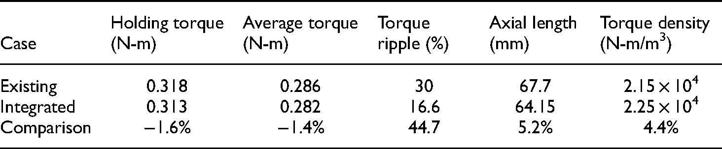
Figure 18 compares the output torque distribution. The average torque of the integrated device was only 1.4% lower than that of the existing design. Therefore, the output torque values were similar. The torque ripple of the integrated device was 44.7% lower than that of the existing design, indicating considerably better output stability. In addition, the axial space was reduced by 5.2%, and the torque density was increased by 4.4%. Table 6 compares the output performance between the integrated device and the existing design. Figure 19 presents a schematic of the integrated device.

Comparison of output torque distribution between the existing design and the integrated device.
Schematic of the integrated device.
Comparison of the output performance between the existing design and the integrated device.
Conclusions
In this study, a novel integrated design concept was developed on the basis of mechanical and electromagnetic design perspectives. By applying the gear profile on the rotor and the stator, a 9:1 two stages PGT reducer is integrated with a standard 42 type 2-pole stepping motor. The shared part is not only the shaft (as the common solutions) but the magnet rotor/stator that have both transmission and magnetic functions. A comparison of the output performance between the existing design and the integrated device revealed that the two devices had similar output and holding torque, but the torque ripple was reduced by approximately 44.7% in the integrated device, indicating considerably improved stability. In addition, the axial space arrangement was reduced by 5.2%, and the torque density was improved by 4.4%.
Footnotes
Acknowledgment
This manuscript was edited by Wallace Academic Editing. The authors are grateful to the Shieh Yih Machinery Industry Co., Ltd.(Taiwan, R.O.C.) for their support on technical advices and equipments.
Declaration of Conflicting Interests
The author(s) declared no potential conflicts of interest with respect to the research, authorship, and/or publication of this article.
Funding
The author(s) disclosed receipt of the following financial support for the research, authorship, and/or publication of this article: This work was supported by the Ministry of Science and Technology, (grant number MOST 107-2218-E-032-002-MY3).